Table of Contents
Advertisement
Quick Links
DCR-HC27E/HC28/HC28E
SERVICE MANUAL
Ver. 1.4 2007.06
Revision History
Revision History
How to use
How to use
Acrobat Reader
Acrobat Reader
N MECHANISM (MDX-N110)
Link
Link
SPECIFICATIONS
MODEL INFORMATION TABLE
SERVICE NOTE
• Precaution on Replacing the VC-416 Board
DCR-HC27E/HC28/HC28E_L2
9-852-135-32
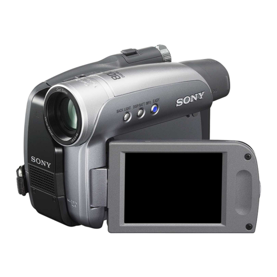
Photo: DCR-HC28E
DISASSEMBLY
BLOCK DIAGRAMS
FRAME SCHEMATIC DIAGRAMS
DIGITAL VIDEO CAMERA RECORDER
Sony EMCS Co.
LEVEL
US Model
Canadian Model
AEP Model
UK Model
East European Model
North European Model
Russian Model
E Model
Australian Model
Argentine Model
Brazilian Model
Chinese Model
Hong Kong Model
Korea Model
SCHEMATIC DIAGRAMS
PRINTED WIRING BOARDS
REPAIR PARTS LIST
Published by Kohda TEC
2
2007F0800-1
© 2007.06
Advertisement
Table of Contents

Related Manuals for Sony DCR-HC27E


Summary of Contents for Sony DCR-HC27E
- Page 1 SCHEMATIC DIAGRAMS MODEL INFORMATION TABLE BLOCK DIAGRAMS PRINTED WIRING BOARDS SERVICE NOTE FRAME SCHEMATIC DIAGRAMS REPAIR PARTS LIST • Precaution on Replacing the VC-416 Board DIGITAL VIDEO CAMERA RECORDER 2007F0800-1 DCR-HC27E/HC28/HC28E_L2 © 2007.06 Sony EMCS Co. 9-852-135-32 Published by Kohda TEC...
- Page 2 These specifications are extracted from instruction manual of DCR-HC27E/HC28/HC28E. SPECIFICATIONS System Input/Output connectors AC Adaptor AC-L25A/L25B Video recording system Audio/Video output Power requirements 2 rotary heads, Helical scanning system 10-pin connector AC 100 - 240 V, 50/60 Hz Video signal: 1 Vp-p, 75 Ω (ohms),...
- Page 3 Model information table Model DCR-HC27E DCR-HC28 DCR-HC28E AEP, UK, EE, NE, US, CND, E, AR Destination NE, RU, E, CH, HK BR, KR Color system NTSC DV Interface IN/OUT IN/OUT • Abbreviation AR : Argentine model AUS : Australian model...
- Page 4 CRITIQUES POUR LA SÉCURITÉ DE FONCTIONNEMENT. NE COMPONENTS WITH SONY PARTS WHOSE PART NUMBERS REMPLACER CES COMPOSANTS QUE PAR DES PIÈSES SONY APPEAR AS SHOWN IN THIS MANUAL OR IN SUPPLEMENTS DONT LES NUMÉROS SONT DONNÉS DANS CE MANUEL OU PUBLISHED BY SONY.
-
Page 5: Table Of Contents
4-1. Frame Schematic Diagrams ············································· 4-1 4-2. Schematic Diagrams ························································ 4-3 4-3. Printed Wiring Boards ··················································· 4-24 4-4. Mounted Parts Location ················································ 4-36 REPAIR PARTS LIST 5-1. Exploded Views ······························································· 5-2 5-2. Electrical Parts List ······················································· 5-12 DCR-HC27E/HC28/HC28E_L2 — 5 —... -
Page 6: Service Note
1-3-3. Exiting the “Forced Power ON” Mode Select page: 0, address: 01, and set data:01. Select page: D, address: 10, set data:00 and press the “PAUSE (Write)” button of the adjustment remote commander. Select page: 0, address: 01, and set data: 00. DCR-HC27E/HC28/HC28E_L2... -
Page 7: Using Service Jig
C : Corrected by customer Indicates the appropriate Refer to “1-5-3. Self-diagnosis Code Table”. H : Corrected by dealer step to be taken. E : Corrected by service E.g. engineer 31 ..Reload the tape. 32 ..Turn on power again. DCR-HC27E/HC28/HC28E_L2... - Page 8 PG fault during normal drum Remove the battery or power cable, connect, and perform operations. operations from the beginning. Phase fault during normal drum Remove the battery or power cable, connect, and perform operations. operations from the beginning. DCR-HC27E/HC28/HC28E_L2...
-
Page 9: Precaution On Replacing The Vc-416 Board
When the data has changed because of board replaceing etc, check the data setting (Exif Model Data) is right. If not, rewrite to the right value. Exif Model Data Data Page Address DCR-HC27E DCR-HC28 DCR-HC28E Writing Method: 1) Select page: 0, address: 01 and set data: 01. -
Page 10: Disassembly
• When remove a connector, dont’ pull at wire of connector. It is possible that a wire is snapped. pieces of gilt may be left inside) • When installing a connector, dont’ press down at wire of connector. It is possible that a wire is snapped. DCR-HC27E/HC28/HC28E_L2... - Page 11 1-12 (Boss) 1-4 (#14) 1-5 (#14) 3-1 (Open the Jack Lid) 3-2 (#2) 1-10 (Claw) 1-15 1-13 1-7 (#2) 3-3 (#2) 1-14 1-11 (Claw) 1 Cabinet (R) block 3 Front Panel Block 1-6 (#2) 1-9 (#2) 1-8 (Open the LCD) DCR-HC27E/HC28/HC28E_L2...
- Page 12 1-2 (#13) (Boss) 1-3 (#12) 1-14 (#3) 1-10 (#12) 1 Hinge block 1-7 (Boss) 3 LCD HELP 2-7 (Claw) 1-5 (#12) 2-3 (#12) 1-15 2-11 2-10 1-9 (#2) 1-13 2-4 (Claw) - 2 8 1-11 (Claw) 2 PD-281 board 1-12 DCR-HC27E/HC28/HC28E_L2...
- Page 13 2-1-3. MAIN BLOCK-1 EXPLODED VIEW HARDWARE LIST 1-1 (#3) 1 EVF block 2-2 (Boss) 3-4 (#2) (Boss) 2-1 (#3) 3 BT Panel Block 2 Lens Block 3-1 (#2) 3-2 (Claw) DCR-HC27E/HC28/HC28E_L2...
- Page 14 EXPLODED VIEW HARDWARE LIST 3 Mechanism Deck 3-5 (Claw) 2-7 (Claw) 3-1 (Boss) 3-2 (Dirrection of the arrow) 2 VC-416 Board 3-3 (Claw) (#15) 1-3 (Boss) 2-4 (#3) - 4 1 3-4 (Claw) 1 Bottom Frame 1-1 (#2) DCR-HC27E/HC28/HC28E_L2 2-5E...
- Page 15 Adhesive tape Fold 2 Hang it on the claw after putting the FP-380 4 Attach two hinge covers as shown in figure. flexible board on the hinge cover (M). Claw Claw Hinge cover (M) Claw Adhesive tape Claw DCR-HC27E/HC28/HC28E_L2 HELP...
-
Page 16: Block Diagrams
3. BLOCK DIAGRAMS Link Link OVERALL BLOCK DIAGRAM (1/5) OVERALL BLOCK DIAGRAM (5/5) OVERALL BLOCK DIAGRAM (2/5) POWER BLOCK DIAGRAM (1/3) OVERALL BLOCK DIAGRAM (3/5) POWER BLOCK DIAGRAM (2/3) OVERALL BLOCK DIAGRAM (4/5) POWER BLOCK DIAGRAM (3/3) DCR-HC27E/HC28/HC28E_L2... - Page 17 MODULATOR CN605 CN1004 (1/4) (1/4) D606 Q1001 MERODY_ENV VSP_SO, XVSP_SCK AC18 IR EMITTER/ NS_LED_K IR_ON OVERALL (2/5) NIGHTSHOT DRIVE (PAGE 3-2) : VIDEO SIGNAL OSD_V : AUDIO SIGNAL OVERALL (5/5) CAM_DD_ON : VIDEO/AUDIO SIGNAL (PAGE 3-5) : VIDEO/AUDIO/SERVO SIGNAL DCR-HC27E/HC28/HC28E_L2...
-
Page 18: Overall Block Diagram (1/5)
S REEL FG AMP SENSOR Q9002 SYS_V TAPE_LED_ON TAPE_LED_K ZOOM_VR_AD DRIVE MIC902 S902 XSYS_RST REC PROOF REC_PROOF REC_PROOF OVERALL (5/5) AA22 (PAGE 3-5) CHIME_SDA, CHIME_SCK CHIME_SDA, CHIME_SCK 4PIN CONNECTOR S901 CC DOWN XCC_DOWN XCC_DOWN : VIDEO/AUDIO/SERVO SIGNAL : SERVO SIGNAL DCR-HC27E/HC28/HC28E_L2... -
Page 19: Overall Block Diagram (2/5)
OVERALL (5/5) TP_Y TP_Y TP_L (PAGE 3-5) TOUCH TOUCH PANEL TP_SEL1 TP_SEL1 TP_R PANEL TP_BOT Q9601, Q9602 Q9306 BACKLIGHT DRIVE IC9302 D9603 - D9605 (BACKLIGHT) LCD/EVF Q9301 - Q9304 BACKLIGHT CONTROL BL_H1 - BL_H3 BACKLIGHT (6/12) DRIVE : VIDEO SIGNAL DCR-HC27E/HC28/HC28E_L2... -
Page 20: Overall Block Diagram (3/5)
SFD_BCK IC6702 SFD_LRCK LANC_SIG LANC_SIG A/D, D/A SFD_FCK CONVERTER (5/12) RECOUT_L DATA_TO_SFD RECOUT_R DCR-HC27E CN604 DV OUT XPWAD, XPWDA OVERALL (1/5) CN604 TPA+, TPA-, TPB+, TPB- TPA+, TPA-, TPB+, TPB- TPA, NTPA, TPB, NTPB (PAGE 3-1) VSP_SO, XVSP_SCK VSP_SO, XVSP_SCK... -
Page 21: Overall Block Diagram (4/5)
VOUT ZOOM_VR_AD LANC_DC IC8001_SI, IC8001_SO, IC8001_SCK, XCS_IC8001 OVERALL (2/5) XCC_DOWN (PAGE 3-2) SYS_V CAM_DD_ON XSYS_RST OVERALL (1/5) OSD_V (PAGE 3-1) Q8002 TP_SEL2 TP SELECT XSYS_RST LANC_SIG SWITCH OVERALL (4/5) TP_X MULTI_JACK_IN (PAGE 3-4) OVERALL (3/5) TP_Y (PAGE 3-3) TP_SEL1 DCR-HC27E/HC28/HC28E_L2... -
Page 22: Power Block Diagram (1/3)
OFF (CHG) (1/2) XPOWER_SW XPOWER_SW POWER XMODE_SW XMODE_SW MODE D_2.8V FR_EVER_SCK HI_EVER_SO, HI_EVER_SCK D_2.8V (NS_2.8V) FR_EVER_SO XCS_DD XCS_DD A_2.8V (EP_2.8V) BATT_IN POWER (3/3) BATT_IN OUTC1 A_4.6V (EP_4.6V) VTR_DD_ON (PAGE 3-8) VTR_DD_ON CTL1 EP_8.5V XLANC_PWR_ON XLANC_POWER_ON WAKE_UP XLANC_ON XLANC_ON XCTL2 DCR-HC27E/HC28/HC28E_L2... -
Page 23: Power Block Diagram (2/3)
D901 CN1007 TAPE LED TAPE_LED_A IC8602 Q9003 64k EEPROM SENSOR_VCC S REEL (7/12) H901 SENSOR Q8605 CHIME_VDD T REEL H902 SENSOR MIC902 4PIN ZM_RST_LED CONNECTOR FC_RST_LED FB8602 D_1.5V CHIME_PWR_CONT CHIME_PWR_CONT XREEL_HALL_ON XREEL_HALL_ON CAM_DD_ON D17 CAM_DD_ON IC8601 CAMERA/MECHA CONTROL (7/12) DCR-HC27E/HC28/HC28E_L2... -
Page 24: Power Block Diagram (3/3)
VDD_P LCD/EVF DRIVE (6/12) 2.5 inch COLOR POFF LCD UNIT XSTBY XSTBY XSTBY_P D9603 - D9605 Q9301 - Q9304 (BACKLIGHT) BL_H1 - BL_H3 BACKLIGHT DRIVE IC9302 Q9601, Q9602 A_OUT LCD/EVF BACKLIGHT D_2.8V TOUCH CONTROL PANEL I/F (6/12) D_2.8V DCR-HC27E/HC28/HC28E_L2 3-8E... -
Page 25: Printed Wiring Boards And Schematic Diagrams
TERMINAL FP-381 FLEXIBLE BOARD J001 DC IN CN9301 CN3101 FP-380 FLEXIBLE BOARD CHECK CN1012 CN1007 CN1010 SI-051 BOARD (SIDE B) CONTROL KEY DCR-HC27E CONTROL KEY BLOCK BLOCK (SS17000) DV OUT BT601 SP901 (CF17000) BATTERY, SPEAKER CN604 LITHIUM SECONDARY DCR-HC28/HC28E CN601... -
Page 26: Schematic Diagrams
PD-281 BOARD (LCD, LCD BACKLIGHT) FP-381 FLEXIBLE BOARD (DC IN) FP-380 FLEXIBLE BOARD FP-031, FP-032, FP-228 FLEXIBLE BOARD FP-386 FLEXIBLE BOARD CONTROL KEY BLOCK (CF17000) (PANEL REVERSE DETECT) SI-051 BOARD (AV/DV/USB CONNECTOR) CONTROL KEY BLOCK (SS17000) COMMON NOTE FOR SCHEMATIC DIAGRAMS DCR-HC27E/HC28/HC28E_L2... - Page 27 In addition, ensure that the receiver is not covered with dusts nor exposed to strong light. Les composants identifiés par une marque 0 sont critiques pour la sécurité. Ne les remplacer que par une pièce portant le numéro spécifie. DCR-HC27E/HC28/HC28E_L2...
- Page 28 FLEXIBLE FLAT CABLE (FFC-063) VSHT PAGE 4-6 of LEVEL3 CL103 VSHT CCD_OUT R10.0/P0 R11.1 /P3.7 L101 IC101 10uH R14.7/P3.0 Q101 CCD IMAGER 2SC3931-BCD-TX IC101 BUFFER ICX610NKF : HC28 ICX611NKF : HC27E/HC28E C101 R101 C105 C104 C103 C102 3300 DCR-HC27E/HC28/HC28E_L2 CD-631...
- Page 29 Schematic diagrams of the VC-416 board are not shown. Pages from 4-6 to 4-17 are not shown. DCR-HC27E/HC28/HC28E_L2...
- Page 30 PANEL_REVERSE C9603 0.0022u REG_GND LND106 REG_GND D9601 CN9604 6P TP_BOT LCD901 (2/2) TP_L TOUCH PANEL N.C. with TP_TOP UNIT TP_R N.C. LND901 CH_GND R9601 Q9601 Q9602 XP411F-TXE XP421F-TXE R9605 TOUCH PANEL I/F TOUCH PANEL I/F DCR-HC27E/HC28/HC28E_L2 PD-281, FP-380, FP-386 4-18...
- Page 31 DF3A6.8FV(TH3SONY) MAZB068H0LS0 CN605 REG_GND R616 C612 A_2.8V(N.C.) C602 PITCH_AD(N.C.) C608 R617 YAW_AD(N.C.) VST_C_RESET(N.C.) AUDIO_L_I/O AUDIO_L_I/O AUDIO_R_I/O CN604 4P AUDIO_R_I/O LF603 DCR-HC27E REG_GND NTPA LANC_SIG DV OUT NTPA LANC_SIG CN604 LANC_DC LANC_DC LF602 F601 NTPB REG_GND (0.2A/50V) DCR-HC28/HC28E VIDEO_I/O NTPB VIDEO_I/O...
- Page 32 PAGE 4-11 UNIT LND017 ACV_GND of LEVEL3 LND018 N.C. LND019 ACV_UNREG LND020 ACV_UNREG LND021 ACV_UNREG LND022 ACV_UNREG HCK2 HCK1 LND023 ACV_UNREG HCK1 HCK2 LND024 BATT/XEXT EVF_GND VSSG C301 C302 EVF_VDD R304 0.1u C303 N.C. D301 MAZS056008S0 DCR-HC27E/HC28/HC28E_L2 LB-121, FP-381 4-20...
- Page 33 MD (N110) sub ass'y (S) A by attaching them with the adhesive agent. HW-105A-CDE-T CONNECTOR T REEL SENSOR These parts are not separately supplied because assembling of these parts requires high accuracy. FP-031 FLEXIBLE BOARD DCR-HC27E/HC28/HC28E_L2 FP-031, FP-032, FP-228 4-21...
- Page 34 REG_GND LND013 LND008 CHARGE_LED_VDD KEY_AD0(SS) LND014 R002 XMODE_SW 1200 D001 POWER D003 XPOWER_SW S002 CAMERA BACK LIGHT OFF(CHG) R001 1200 S001 S001 PANEL OPEN/CLOSE (EJECT) VC-416 (5/12) SP901 CN1001 SPEAKER PAGE 4-10 of LEVEL3 S004 START/STOP DCR-HC27E/HC28/HC28E_L2 CF17000, SS17000 4-22...
-
Page 35: Printed Wiring Boards
4-3. PRINTED WIRING BOARDS Link Link CD-631 BOARD SI-051 BOARD PD-281 BOARD (SIDE A) LB-121 BOARD PD-281 BOARD (SIDE B) FP-381 FLEXIBLE BOARD FP-386 FLEXIBLE BOARD FP-031, FP-032, FP-228 FLEXIBLE BOARD COMMON NOTE FOR PRINTED WIRING BOARDS MOUNTED PARTS LOCATION DCR-HC27E/HC28/HC28E_L2... - Page 36 : pattern of the rear side (The other layers’ patterns are not indicated) • Through hole is omitted. • There are a few cases that the part printed on diagram isn’t mounted in this model. • C: panel designation DCR-HC27E/HC28/HC28E_L2 4-24...
- Page 37 CD-631 (2 layers) : Uses unleaded solder. CD-631 BOARD (SIDE A) CD-631 BOARD (SIDE B) IC101 Note: IC101 is not included in CD-631 complete board. 1-868-293- 1-868-293- 21 DCR-HC27E/HC28/HC28E_L2 CD-631 4-26...
- Page 38 Printed wiring boards of the VC-416 board are not shown. Pages from 4-27 to 4-28 are not shown. DCR-HC27E/HC28/HC28E_L2...
- Page 39 PD-281 (2 layers) : Uses unleaded solder. PD-281 BOARD (SIDE A) R9605 CN9604 R9601 CN9601 R9604 D9608 D9606 D9607 R9606 Q9603 C9606 1-868-305- DCR-HC27E/HC28/HC28E_L2 PD-281 (SIDE A) 4-29...
- Page 40 PD-281 (2 layers) : Uses unleaded solder. PD-281 BOARD (SIDE B) D9605 (BACKLIGHT) D9603 (BACKLIGHT) D9604 (BACKLIGHT) 1-868-305- DCR-HC27E/HC28/HC28E_L2 PD-281 (SIDE B) 4-30...
- Page 41 LND104 LND106 LND601 F P-3 8 6 S101 > < BT601 BATTERY D606 LITHIUM IR EMITTER/ NIGHT SHOT SECONDARY RB602 1-867-795- DCR-HC27E DV OUT CN604 BT601 DCR-HC28/HC28E SOL601 BH601 LND602 (BATTERY HOLDER) CN601 A/V OUT R622 CN602 C616 C612 R617...
- Page 42 LB-121 BOARD (SIDE B) D301 C301 R304 CN302 D302 (BACKLIGHT) CN301 1-868-308- 1-868-308- FP-381 FLEXIBLE BOARD Note: BH001 and J001 are not included in FP-381 flexible board. J001 > < DC IN 1-867-779- FP-381 BH001 BATTERY TERMINAL DCR-HC27E/HC28/HC28E_L2 LB-121, FP-381 4-32...
- Page 43 4 PIN CONNECTOR 1-867-810- 11 1-864-865- 11 FP-228 FLEXIBLE BOARD H902 SENSOR T REEL SENSOR 1-677-049- M902 LOADING MOTOR H901 S REEL SENSOR (Dilect Solder) (Dilect Solder) FP-031 FLEXIBLE BOARD 1-867-811- Q901 TAPE END SENSOR DCR-HC27E/HC28/HC28E_L2 FP-031, FP-032, FP-228 4-33...
- Page 44 Mounted parts location of the VC-416 board are not shown. Page 4-34 to 4-35 are not shown. DCR-HC27E/HC28/HC28E_L2...
-
Page 45: Mounted Parts Location
* D603 * D9603 B5 D606 * D9604 C5 * D9605 A5 F601 F602 Q9601 A4 Q9602 A4 FB601 FB602 R9602 A3 R9603 A3 * LF602 R9604 A3 * LF603 R9607 B4 * R623 * R624 DCR-HC27E/HC28/HC28E_L2 PD-281, SI-051 4-36E... -
Page 46: Repair Parts List
BLOCK ASSEMBLY-1 BLOCK ASSEMBLY-2 ELECTRICAL PARTS LIST Link ELECTRICAL PARTS LIST Link ACCESSORIES ACCESSORIES CD-631 BOARD FP-380 FLEXIBLE BOARD PD-281 BOARD FP-031 FLEXIBLE BOARD FP-381 FLEXIBLE BOARD SI-051 BOARD FP-032 FLEXIBLE BOARD FP-386 FLEXIBLE BOARD FP-228 FLEXIBLE BOARD LB-121 BOARD DCR-HC27E/HC28/HC28E_L2... - Page 47 AUS : Australian model : Brazilian model : Chinese model CND : Canadian model : East European model HK : Hong Kong model : Japanese model : Tourist model : Korea model : North European model : Russian model DCR-HC27E/HC28/HC28E_L2...
-
Page 48: Exploded Views
Front Panel Block Cabinet (R) Block (See page 5-3.) (See page 5-4.) Ref. No. Part No. Description Ref. No. Part No. Description X-2108-030-1 CABINET (172) ASSY, NS 2-635-562-31 SCREW (M1.7) (Black) 2-664-983-31 CABINET (UPPER (172)) 2-599-475-11 SCREW (M1.7) (Silver) DCR-HC27E/HC28/HC28E_L2... - Page 49 2-664-940-01 SCREW (172), FILTER MIC901 1-542-513-21 MICROPHONE 2-664-986-01 COVER, JACK * 54 2-664-946-01 RETAINER, MICROPHONE 3-078-890-01 SCREW, TAPPING (Silver) 3-080-204-21 SCREW, TAPPING, P2 (Black) A-1204-538-A SI-051 (BBM) BOARD, COMPLETE * 56 2-672-995-01 SHEET (F) 3-941-343-21 TAPE (A) 2-664-942-11 RING (173), FRONT DCR-HC27E/HC28/HC28E_L2...
- Page 50 X-2159-374-1 CABINET (M (211)) ASSY, P 2-635-562-31 SCREW (M1.7) (Black) X-2159-375-1 CABINET (R (211)) ASSY 2-660-401-01 SCREW (M1.7), NEW TRU-STAR, P2 (Red) 2-666-791-01 LIGHT GUIDE (2.5) 3-080-204-21 SCREW, TAPPING, P2 (Black) 1-479-506-11 KEY BLOCK, CONTROL (CF17000) 3-085-397-01 SCREW (Silver) DCR-HC27E/HC28/HC28E_L2...
- Page 51 1-780-064-21 BATTERY TERMINAL BOARD (Note) 1-867-779-13 FP-381 FLEXIBLE BOARD J001 1-815-792-11 CONNECTOR, DC-IN (7.2V) (Note) X-2108-652-1 PANEL (172) ASSY, BT 2-664-984-01 COVER, DC (IN) 2-635-562-31 SCREW (M1.7) (Black) 2-664-985-01 LID, CPC 2-660-401-01 SCREW (M1.7), NEW TRU-STAR, P2 (Red) 3-078-890-11 SCREW, TAPPING (Silver) DCR-HC27E/HC28/HC28E_L2...
- Page 52 (Note 1, 2) 1-788-242-11 OPTICAL FILTER BLOCK IC101 8-753-244-71 ICX611NKF-13 (CCD IMAGER) (HC27E/HC28E) 2-318-138-01 RUBBER, SEAL 1070 (Note 1, 2) * 205 1-830-778-11 CABLE, FLEXIBLE FLAT (FFC-063) 3-080-204-21 SCREW, TAPPING, P2 (Black) A-1204-536-A CD-631 (BBM) BOARD, COMPLETE 3-085-397-01 SCREW (Silver) DCR-HC27E/HC28/HC28E_L2...
- Page 53 X-2103-696-1 VF (172) ASSY * 255 2-638-816-01 PLATE (TFT), DEFLECTION X-2103-695-1 EYE CUP ASSY 2-664-671-01 SPACER, LCD LCD902 8-753-245-09 LCX059CKK-1 3-941-343-21 TAPE (A) * 258 1-867-777-11 FP-379 FLEXIBLE BOARD 2-660-401-01 SCREW (M1.7), NEW TRU-STAR, P2 (Red) 3-080-204-21 SCREW, TAPPING, P2 (Black) DCR-HC27E/HC28/HC28E_L2...
- Page 54 * 302 2-664-976-01 FRAME (171), BOTTOM 2-660-401-01 SCREW (M1.7), NEW TRU-STAR, P2 (Red) 1-479-507-41 KEY BLOCK, CONTROL (SS17000) 3-062-214-01 SCREW (M1.4X1.5) (Silver) A-1217-481-A VC-416 COMPL (BBM) SERVICE * 305 1-830-775-11 CABLE, FLEXIBLE FLAT (FFC-060) 2-659-500-01 LABEL, FUSE REPLACEMENT CAUTION DCR-HC27E/HC28/HC28E_L2...
- Page 55 2-342-918-01 TG6 CATCHER 3-703-816-08 SCREW (M1.4X1.4), SPECIAL HEAD A-1156-601-A MD (N110) SUB ASSY (S) A X-2149-724-1 CASSETTE COMPARTMENT ASSY 3-703-816-13 SCREW (M1.4X2.0), SPECIAL HEAD 2-342-926-01 SPRING (ARM S), TENSION COIL 3-315-414-31 WASHER 2-546-417-01 SCREW (M1.4) M901 A-1154-545-A DRUM (DEH-33E-R) (SERVICE) DCR-HC27E/HC28/HC28E_L2...
- Page 56 2-342-705-01 GEAR (T), GL X-2024-466-1 COASTER (T) ASSY 2-342-902-01 SPRING, TENSION REGULATOR X-2024-469-1 ARM (T) ASSY, GL X-2067-291-1 TABLE ASSY, T REEL 2-342-716-01 SPRING (T), TORSION COIL X-2067-295-4 ARM ASSY, PINCH 3-703-816-08 SCREW (M1.4X1.4), SPECIAL HEAD (for adjustment) DCR-HC27E/HC28/HC28E_L2 5-10...
- Page 57 2-342-615-01 GEAR, NO.2 Q901 6-550-672-01 TRANSISTOR PT4850FJE00F (TAPE END) 2-342-691-01 GEAR, NO.1 Q902 6-550-672-01 TRANSISTOR PT4850FJE00F (TAPE TOP) 2-637-945-01 MOTOR HOLDER S901 1-786-448-22 SWITCH, PUSH (1 KEY) (CC DOWN) 3-895-822-71 SCREW (M1.2X2), SPECIAL, 0 2-342-689-01 WORM SHAFT (2J) DCR-HC27E/HC28/HC28E_L2 5-11...
-
Page 58: Electrical Parts List
******************** C9606 1-125-777-11 CERAMIC CHIP 0.1uF (This flexible board with S903 is included in MD (N110) SUB ASSY (S) A (A-1156-601-A).) Note: Be sure to read “Precautions for Replacement of DCR-HC27E/HC28/HC28E_L2 Imager” on page 4-3 when changing the imager. 5-12... - Page 59 < LINE FILTER > LF602 1-400-633-21 COMMON MODE CHOKE COIL LF603 1-400-633-21 COMMON MODE CHOKE COIL • Refer to page 5-1 for mark 0. CAUTION Danger of explosion if battery is incorrectly replaced. DCR-HC27E/HC28/HC28E_L2 Replace only with the same or equivalent type. 5-13...
- Page 60 3-093-691-61 (E, HK, CH) ENGLISH / FRENCH / SIMPLIFIED CHINESE for CHINA / TRADITIONAL CHINESE for HONG KONG 3-093-691-71 (E) ENGLISH / TRADITIONAL CHINESE for TAIWAN / SPANISH / PORTUGUESE • Refer to page 5-1 for mark 0. DCR-HC27E/HC28/HC28E_L2 5-19E...
- Page 61 The differences with other area models are only accessories. Model information table & : Point added portion. Page Former DCR-HC28E DCR-HC28E NE, RU, E, CH, HK NE, RU, E, AUS, CH, HK IN/OUT IN/OUT 2007B0800-1 DCR-HC27E/HC28/HC28E_L2 © 2007.02 Sony EMCS Co. 9-852-135-82 Published by Kohda TEC...
- Page 62 ENGLISH / FRENCH / SIMPLIFIED CHINESE for CHINA / TRADITIONAL CHINESE for HONG KONG 3-093-691-71 (E) ENGLISH / TRADITIONAL CHINESE for TAIWAN / SPANISH / PORTUGUESE • Refer to page 5-1 on the service manual for marks 0. DCR-HC27E/HC28/HC28E_L2 — 2 —...
- Page 63 So Suffix No. of part number for VC-416 board has been changed from ea to ta. • When the machine needs to be repaired, please refer to page 2 to discriminate the VC board's suffix No. 2007F0800-1 DCR-HC27E/HC28/HC28E_L2 © 2007.06 Sony EMCS Co. 9-852-135-86 Published by Kohda TEC...
- Page 64 Data Suffix No. 00 to 0F F1 to FF A/V OUT jack A/V OUT Adjustment remote AC adaptor AC IN commander Multi cable (NEW LANC JIG) for service (J-6082-535-A) To DC IN jack (RM-95) Fig. 1 DCR-HC27E/HC28/HC28E_L2 — 2 —...
- Page 65 IC6702 SFD_LRCK A/D, D/A SFD_FCK CONVERTER (5/12) RECOUT_L DATA_TO_SFD RECOUT_R XPWAD, XPWDA VSP_SO, XVSP_SCK VSP_SO, XVSP_SCK OVERALL (1/5) XCS_AU1 (PAGE 3-1) BEEP SI-051 BOARD (2/4) MIC901 CN605 CN1004 MICROPHONE (2/4) (2/4) CN602 INT_MIC_L INT_MIC_L INT_MIC_R INT_MIC_R DCR-HC27E/HC28/HC28E_L2 — 3 —...
- Page 66 (4/12) IC6702 A/D, D/A CONVERTER (5/12) L6701 L6701 AU_2.8V AU_2.8V L6702 L6702 AU_4.6V AU_4.6V 1/3) 1/3) L6704 IC6701 L6704 IC6701 VIDEO OUT, VIDEO OUT, AUDIO I/O AUDIO I/O (5/12) (5/12) Q6701 Q6701 3.4V REG 3.4V REG DCR-HC27E/HC28/HC28E_L2 — 4 —...
- Page 67 0 are critical for safety. Replace only with part number specified. Les composants identifiés par une marque 0 sont critiques pour la sécurité. Ne les remplacer que par une pièce portant le numéro spécifié. DCR-HC27E/HC28/HC28E_L2 — 5 —...
- Page 68 0 are critical for safety. Replace only with part number specified. Les composants identifiés par une marque 0 sont critiques pour la sécurité. Ne les remplacer que par une pièce portant le numéro spécifié. DCR-HC27E/HC28/HC28E_L2 — 6 —...
- Page 69 0 are critical for safety. Replace only with part number specified. Les composants identifiés par une marque 0 sont critiques pour la sécurité. Ne les remplacer que par une pièce portant le numéro spécifié. DCR-HC27E/HC28/HC28E_L2 — 7 —...
- Page 70 0 are critical for safety. Replace only with part number specified. Les composants identifiés par une marque 0 sont critiques pour la sécurité. Ne les remplacer que par une pièce portant le numéro spécifié. DCR-HC27E/HC28/HC28E_L2 — 8 —...
- Page 71 HARDWARE LIST (1/4) #1: M1.7 X 2.5 #2: M1.7 X 4.0 #3: M1.7 X 2.5 #4: M1.4 X 2.5 (Tapping) (Black) (Black) (Red) (Dark Silver) 2-635-562-11 2-635-562-31 2-660-401-01 3-348-998-81 #5: M1.7 X 3.5 (Tapping) #6: M1.4 X 1.7 #7: M1.7 X 1.6 #8: M1.7 X 3.5 (Tapping) (Black) (Silver)
- Page 72 HARDWARE LIST (2/4) #21: M1.4 X 3.0 #22: M1.7 X 5.0 (Tapping) #23: M1.7 X 4.0 (Tapping) #24: B1.7 X 5.5 (Tapping) (Black) (Silver) (Black) (Black) 2-662-396-21 3-083-261-01 3-080-204-11 4-679-805-11 #25: M1.7 X 3.0 #26: M1.4 X 2.0 #27: M1.4 X 2.0 #28: M1.4 X 4.0 (Tapping) (Black) (Silver)
- Page 73 HARDWARE LIST (3/4) #41: M3.0 X 8.0 (Tapping) #42: M2.0 X 4.0 (Tapping) #43: M1.7 X 4.0 #44: M1.7 X 3.0 (Tapping) (Silver) (Silver) (Red) (Silver) 3-065-748-01 7-628-253-00 2-660-401-31 3-078-890-61 #45: M1.4 X 2.5 #46: M1.7 X 3.0 #47: M1.4 X 3.0 (Tapping) #48: M1.7 X 2.5 (Silver) (Red)
- Page 74 HARDWARE LIST (4/4) #64: M1.7 X 5.0 (Tapping) #61: M3.0 X 10.0 #62: M2.0 X 3.0 #63: M5.0 X 12.5 (Silver) (Black) (Silver) (Black) 2-666-551-21 7-682-549-09 3-080-202-21 3-060-811-21 12.5 10.0...
- Page 75 [Description of main button functions on toolbar of the Adobe Acrobat Reader Ver5.0 (for Windows)] Toolbar Printing a text Reversing the screens displayed once • To reverse the previous screens (operation) one by one, click 1. Click the Print button 2.
- Page 76 S.M. Correction : Page 3-2, 3-3, 3-4, 3-5, 3-6, 3-7, 3-8, 4-1, 4-5, 4-19, 4-21, 4-33, 5-4, 5-9, 5-10, 5-11, 5-12, 5-13, 5-19E 2007.06 Supplement-2 • SI-051 Board Modification (S2 DI07-041) • Change of Repair Parts List • VC-416 Board Modification DCR-HC27E/HC28/HC28E_L2...
Need help?
Do you have a question about the DCR-HC27E and is the answer not in the manual?
Questions and answers
BONJOUR OU TROUVEZ DES ADAPTATEUR POUR SE CAMESCOPE
Adapters for the Sony DCR-HC27E camcorder can be found on online marketplaces such as Amazon. However, availability may vary, and some listings may not have featured offers. It is recommended to check different sellers under "See All Buying Options" on the product page.
This answer is automatically generated