Advertisement
Quick Links
Advertisement

Related Manuals for senses akustik DUO


Summary of Contents for senses akustik DUO
- Page 1 INSTALLATION MANUAL|DUO...
- Page 2 Kolo Duo. 7. Verify that the power source for the Kolo Duo can safely handle a load of 10 amps. When the ventilation is active, the LED light is at its full illumination, and the power charging station is not in use, the wattage usage is 24W.
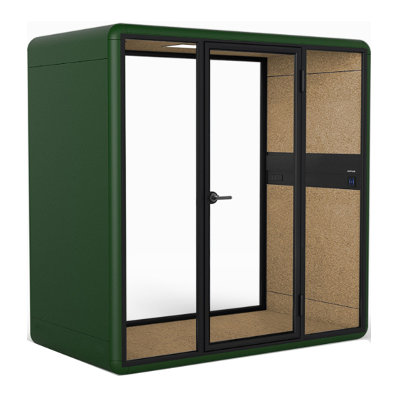
- Page 3 Required Tools Drill 90 Degree Drill Adaptor Rubber Mallet Ratchet Wrench - Metric Socket Phillips Screw Driver Allen Key Set Senses Akustik Installation manual...
- Page 4 Tool Kit: Power Cord Dowel Pin Nº1-6 Nº1-4 Nº1-5 Exterior Handle R ose Mounting Plate Nº1-7 Nº1-9 Nº1-8 Interior Handle S crew Cover S ingle M4x40mmL Nº1-10 Nº1-11 Nº2-1 Nº6 Screw Cover Double Bottom Socket Cover Tile Floor Corner Senses Akustik Installation manual...
- Page 5 Roof Corner + E lectric Nº4 Nº5 Nº6 Side Wall + E lectric Side Wall Floor Nº7 Nº8-1 Nº8-2 R oof Horizontal Frames Horizontal Frame Covers Nº9-2 Nº9-1 Nº10 Vertical Frame Covers Vertical Frames Frame Corners Senses Akustik Installation manual...
- Page 6 Nº11 Nº12 Nº13 Side Glass Back Glass Glass Door Nº16 Nº14 Nº15 Center Floor PET Tile Side Floor PET Tiles Top Side Panels Nº17 Bottom Side Panels Senses Akustik Installation manual...
- Page 7 Tool Kit: Screw Pack List A / B M8 x 50 M8 x 25 Spring Washer M4 x 25 Senses Akustik Installation manual...
- Page 8 Handle with care! Parts are NOT fully assembled out of the packaging. Please disjoint the parts before proceeding with the following step Nº1-3 Dowel Pin M8 x 50 Nº2-1 Floor Corner Nº6 Nº2-2 Floor Floor Corner + Electric Senses Akustik Installation manual...
- Page 9 Step 2. Internet Montior (Yellow) (Green) Yellow Green Montior Internet (Green) Yellow Green (Yellow) Nº4 S ide Wall + Electric Nº5 S ide Wall M8 x 50 M8 x 50 Senses Akustik Installation manual...
- Page 10 Handle with care! Parts are NOT fully assembled out of the packaging. Please disjoint the parts before proceeding with the following step. M8 x 50 Nº3-2 R oof Corner + Electric Nº7 R oof Nº3-1 Roof Corner Nº1-3 Dowel Pin Senses Akustik Installation manual...
- Page 11 Step 4. M8 x 50 M8 x 50 Senses Akustik Installation manual...
- Page 12 Step 5. Spring Washer Nº8-1 Horizontal Frame M8 x 25 Senses Akustik Installation manual...
- Page 13 Step 6. Spring Washer M8 x 25 Nº9-1 Vertical Frame Nº10 Frame Corner Senses Akustik Installation manual...
- Page 14 Step 7. Nº11 Nº12 Nº11 S ide Glass Back Glass S ide Glass Senses Akustik Installation manual...
- Page 15 Step 8. Nº9-1 Vertical Frame Nº10 Frame Corner Nº8-2 Horizontal Frame Cover Senses Akustik Installation manual...
- Page 16 Step 9. Spring Washer M8 x 25 Senses Akustik Installation manual...
- Page 17 Step 10. Nº10 Nº8-2 Frame Corner Nº8-1 Horizontal Frame Cover Horizontal Frame Nº10 Frame Corner Nº9-2 Vertical Frame Cover Nº9-2 Vertical Frame Cover Nº10 Frame Corner Senses Akustik Installation manual...
- Page 18 Step 11. Spring Washer M8 x 25 Senses Akustik Installation manual...
- Page 19 Step 12. Nº8-1 Spring Washer Horizontal Frame M8 x 25 Senses Akustik Installation manual...
- Page 20 Step 13. Spring Washer M8 x 25 Nº9-1 Vertical Frame Nº10 Frame Corner Senses Akustik Installation manual...
- Page 21 Step 14. Nº1-8 M4x40mmL Nº1-6 INTERIOR R ose EXTERIOR Nº1-7 Interior Handle Nº1-5 Nº1-4 Mounting Plate E xterior Handle Senses Akustik Installation manual...
- Page 22 Step 15. Nº11 Nº13 Nº11 Side Glass Glass Door S ide Glass Senses Akustik Installation manual...
- Page 23 Step 16. Nº9-1 Vertical Frame Nº10 Frame Corner Nº8-1 Nº10 Nº8-2 Horizontal Frame Cover Horizontal Frame Frame Corner Senses Akustik Installation manual...
- Page 24 Step 17. Spring Washer M8 x 25 Senses Akustik Installation manual...
- Page 25 Step 18. Nº8-2 Nº8-1 Nº10 Horizontal Frame Cover Horizontal Frame Frame Corner Nº10 Frame Corner Nº9-2 Nº9-2 Vertical Frame Cover Nº10 Vertical Frame Cover Frame Corner Senses Akustik Installation manual...
- Page 26 S tep 19. Spring Washer M8 x 25 Nº8-1 Horizontal Frame Senses Akustik Installation manual...
- Page 27 Step 20. M4 x 25 Nº1-10 Screw Cover Double Nº1-9 Screw Cover S ingle Nº1-9 Screw Cover S ingle Senses Akustik Installation manual...
- Page 28 Step 21. HEADS UP Use an allen wrench to adjust each of the 8 glides, levelling the Duo so that the seams and shadow-lines are square Senses Akustik Installation manual...
- Page 29 Step 22. Nº15 Side Floor PET Tiles Nº15 Side Floor PET Tiles Nº14 Nº1-11 Nº6 Center Floor PET Tile Bottom Socket Cover Tile Senses Akustik Installation manual...
- Page 30 Step 23. Nº16 Top Side Panels Nº17 Bottom Side Panels Senses Akustik Installation manual...
- Page 31 Step 24. Nº1-2 Tool Kit: Power Cord Senses Akustik Installation manual...
- Page 32 Senses Akustik Installation manual...
- Page 33 info@sensesakustik.com www.sensesakustik.com...
Need help?
Do you have a question about the DUO and is the answer not in the manual?
Questions and answers