Table of Contents
Advertisement
Quick Links
nrgCONTROL-BT
Installation Guide
nrgSMART describes the family of distributed network
monitoring and management products, from BDFBs to
high-current and low-current secondary panels.
nrgSMART allows you to collect performance data on
distributed assets and tools to help you efficiently
access business critical and actionable information.
Amphenol Network Solutions recognizes the industry
need to manage distributed assets more efficiently, get
better power performance out of deployed assets, as
well as pursue realistic and achievable alternative
energy goals. Through nrgSMART, access to data at
the equipment level provides the foundation for
managing performance of a distributed DC power
distribution system.
•
Individual circuit monitoring: Measure power at
the circuit level. This enables powerful trend
analysis and insights into equipment performance
and enables preventative maintenance processes.
−
High accuracy, 100% passive monitoring,
modular sensor modules
•
Collect feed voltage, circuit current and
temperature
•
Network data collection: Intelligent interpretation
of the collected data, based on equipment data
signature (smart alarms), drives relevant business
decisions. The nrgCONTROL-BT uses an SNMP
interface to send data to a customer's network
management system such as Forseer or Osprey.
Advertisement
Table of Contents

Related Manuals for Amphenol nrgCONTROL-BT


Summary of Contents for Amphenol nrgCONTROL-BT
- Page 1 (smart alarms), drives relevant business managing performance of a distributed DC power decisions. The nrgCONTROL-BT uses an SNMP distribution system. interface to send data to a customer’s network management system such as Forseer or Osprey.
-
Page 2: Table Of Contents
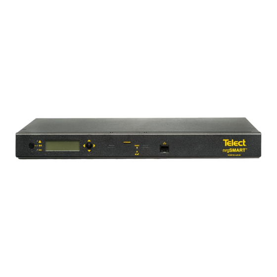
Section Three: nrgCONTROL-BT Dimensions ......................11 List of Figures Fig. 1: nrgCONTROL-BT front view ..........................3 Fig. 2: nrgCONTROL-BT rear view without tie bar shown ....................3 Fig. 3: nrgCONTROL-BT DC power pin out ........................3 Fig. 4: Bracket orientation as shipped ..........................6 Fig. -
Page 3: Section One: Overview
For new deployments the controller interface is built into the nrgBDFB. For expansion, single rack deployment or outdoor enclosures, Amphenol Network Solutions provides the 1RU controller. The nrgCONTROL-BT is capable of connecting to DC power in the range of -20V to -57V. Redundant power input is also configurable based on the pin-out description in Fig. 3. -
Page 4: Specifications
(e.g., use of power strips). • Disconnect Device: Incorporate a readily accessible disconnect device in the building installation wiring. Amphenol Network Solutions nrgCONTROL-BT All rights reserved. 05.09.2023 145122-5 Rev A2 509.926.6000 — amphenol-ns.com... -
Page 5: Section Two: Installation
Amphenol Network Solutions Quality at quality@amphenol-ns.com or call 1-509-926-6000. Keep all documentation that comes with your shipment. Amphenol Network Solutions is not liable for transit damage. If the product is damaged, please report it to the carrier and contact Amphenol Network Solutions. -
Page 6: Rack Mounting
2.2 Rack Mounting The nrgCONTROL-BT panel can be mounted in 19-inch and 23-inch EIA and WECO racks. The nrgCONTROL-BT panel can be flush-mounted to 4-inch extended in " increments. 1. Unscrew the mounting brackets from the panel and turn them to the mounting position. -
Page 7: Grounding
1. The nrgCONTROL-BT panel provides power to the connected PDU panels via the nrgNET cabling. The nrgNET cabling power is protected by a 4A GMT fuse located on the rear panel of the nrgCONTROL-BT panel. To replace this fuse, follow these steps: Refer to Figures 3 and 6 a. -
Page 8: Nrgcontrol Nrgnet Connectivity
1. Remove the nrgNET connectors from the nrgNET OUT 1 and nrgNET OUT 2 on the rear of the nrgCONTROL-BT. 2. Insert the two service links provided into the nrgNET OUT 1 and nrgNET OUT 2 on the rear of the nrgCONTROL-BT as shown in Fig. - Page 9 WARNING! Failure to connect the wires to the proper pins can result in a failure to communicate between the nrgCONTROL-BT and the attached nrgSMART panels. nrgNET Pin Outs Pin Number Label Wire Color Pin 1 COM + White Pin 2...
- Page 10 Click on “Proceed to [IP Address] (unsafe)” at the bottom left corner. Scan QR Code for our full online User Guide Amphenol Network Solutions nrgCONTROL-BT All rights reserved. 05.09.2023 145122-5 Rev A2 509.926.6000 — amphenol-ns.com...
-
Page 11: Section Three: Nrgcontrol-Bt Dimensions
Front view Rear view Amphenol Network Solutions assumes no liability from the application or use of these products. Neither does Amphenol Network Solutions convey any license under its patent rights or the patent rights of others. This document and the products described herein are subject to change without notice. - Page 12 Modification Any modification made to this device that are not approved by Amphenol Network Solutions may void the authority granted to the user by the FCC to operate this equipment.
Need help?
Do you have a question about the nrgCONTROL-BT and is the answer not in the manual?
Questions and answers