Table of Contents
Advertisement
1st
Instruction Manual
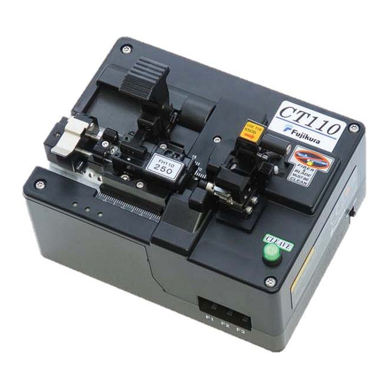
Advanced Optical Fiber Cleaver
CT110/111
Thank you for purchasing Fujikura's Advanced
Optical Fiber Cleaver
.
Please read this instruction manual carefully
before operating the equipment.
Adhere to all safety instructions and
warnings contained in this manual.
Keep this manual in a safe place.
There may be updates without notice.
Advertisement
Table of Contents

Subscribe to Our Youtube Channel
Related Manuals for Fujikura CT110


Summary of Contents for Fujikura CT110
- Page 1 Instruction Manual Advanced Optical Fiber Cleaver CT110/111 Thank you for purchasing Fujikura’s Advanced Optical Fiber Cleaver Please read this instruction manual carefully before operating the equipment. Adhere to all safety instructions and warnings contained in this manual. Keep this manual in a safe place.
- Page 2 Please consent beforehand. The software equipped in the cleaver and its related documents are protected by copyright laws and international treaty provisions as well as other intellectual property laws. Copying some or all of instruction manual without notice is forbidden. Moreover, without permission from our company, it cannot be used on the Copyright Act except when used as an individual.
-
Page 3: Table Of Contents
Table of Contents Safety Information ............1 General Information ............4 Introduction ...................... 4 Components ..................... 5 Description ....................... 6 Cleaving Operation ............9 Power Supply ....................9 How to Operate ....................11 Cleave Mode Selection .................. 14 Adjusting the Total Fiber Length ..............18 Using the Coating Adjuster ................ -
Page 4: Safety Information
Safety Information Thank you for purchasing Fujikura’s Advanced Optical Fiber Cleaver In this instruction manual, the processes and procedures are documented which should be observed in order to use this product safely. This cleaver has been designed for cleaving glass optical fibers. Cleaving should not be... - Page 5 / humid environments, or when water condensation is present on the unit. This may result in electric shock, cleaver malfunction, or poor cleaving performance. When water condensation is present, leave the cleaver powered off and allow to air-dry at room temperature for at least 24 hours. CT110/111_Rev1...
- Page 6 [Recycling] To recycle this product, disassemble it first, sort each part separately by material components and follow your local recycling regulations. [Disposal] This product can be disposed of same as the standard electric poroducts. Follow your local disposal regulations. CT110/111_Rev1...
-
Page 7: General Information
To master the CT110 and CT111, read this instruction manual prior to use. CT110 The CT110 model is applicable for cleaving fibers having a cladding diameter of up to 250μm. This model does not have the angled cleaving unit. CT111 The CT111 model is applicable for cleaving fibers having a cladding diameter of up to 250μm. -
Page 8: Components
General Information Components The contents of the standard package are shown; please confirm all items are included. Advanced Fiber Cleaver CT110 CT111 (without angle cleaving base) (with angle cleaving base) Standard Components Name Item Amount AC Adapter ADC-21 AC Cord... -
Page 9: Description
General Information Description CT110 Blade Unit Fiber Holder Clamp Clamp Unit Positioning Spacer Cleave Button Coating Adjuster Length Scale LED Indicators CT111 Rotary Base CT110/111_Rev1... - Page 10 General Information Angle Scale Right Lever (CT111 only) Left Lever Fiber Clamp Holder Clamp Function Keys Cleave Angle Adjustment Screw ON/OFF Switch (CT111 only) USB Port DC Power Port Battery Box Cover CT110/111_Rev1...
- Page 11 Starts the cleaving operation. Displays the current blade position. F1 key Hold the F1 key to enter “blade position change” mode. Displays the current cleave mode. F2 key Hold the F2 key to enter “cleave mode selection” mode. F3 key CT110/111_Rev1...
-
Page 12: Cleaving Operation
Cleaving Operation Power Supply AC adapter Only use a genuine Fujikura AC adapter and AC power cord. 2. Plug the AC cord into the wall and plug the cord into the AC port of the adapter block. Connect the ACC-## to wall... - Page 13 Cleaving Operation Power ON/OFF Remove any fiber before powering on the cleaver. 2. Slide the power switch to ON. CT110/111_Rev1...
-
Page 14: How To Operate
Provides a consistent total fiber length after cleaving by maintaining constant pressure toward the blade. After releasing the Left-hand lever, it can prevent the fiber holder from being picked up by the clamp pad. Plungers provide constant Positioning Spacer forward pressure Fiber Holder CT110/111_Rev1... - Page 15 5. Close the right-hand lever to clamp the optical fiber. 6. For angled cleaving, rotate the angled cleaving base counterclockwise to twist the optical fiber. Fiber Clamp Cleave Button Clamp the optical fiber Rotate the Angled Cleaving Base counterclockwise with the right clamp. for angled cleaving. (CT111 only) CT110/111_Rev1...
- Page 16 When the right-hand lever is opened, the clamp unit will return to its home position. If repeating the cleave operation, return to step 3. Applicable fiber Applicable cladding dia. φ80 to 250μm Applicable coating dia. Φ81 to 2000μm Total fiber length 11mm to 44mm Fiber length Cleave length 3mm to 44mm CT110/111_Rev1...
-
Page 17: Cleave Mode Selection
LED 2 flashes green 3 times: 125μm cleave mode is selected. LED 3 flashes green 3 times: 250μm cleave mode is selected. Within this device, different cleave modes can be added and edited using the Data Connection PC software. Refer to [Cleave Settings]. CT110/111_Rev1... - Page 18 Cleaving Operation Fiber Holders The CT110/111 can be used with 3 types of fiber holders. Each fiber holder requires the fiber holder base to be set up accordingly. Compatible Fiber Holders: Fiber Holder Adapter for FH-70 AD-CT110-FH70 FH110 H110 FH-100...
- Page 19 FH110 fiber holder, the cleaver can be set to detect the fiber holder and retrieve the assigned cleave mode. For more information about registering with FH110 fiber holders, refer to the [Fiber Holder Registration] section. Fiber holder management is unavailable when using battery power. CT110/111_Rev1...
- Page 20 Cleaving Operation Replacing the Fiber Holder Adapter FH-70 series fiber holders can be used after replacing the factory fiber holder adapter with the FH-70 Series Fiber Holder Adapter. AD-CT110-FH70 FH-70 Fiber Holder Adapter for FH-70 HEX-01 1.5mm Hex wrench Loosen the screw, then remove Attach the Fiber Holder Adapter the Fiber Holder Adapter.
-
Page 21: Adjusting The Total Fiber Length
Push against scale Push the entire fiber holder base unit toward the scale. If not flush to the scale, the fiber holder base may not be parallel to the V-groove base. Poor cleaving results or fiber breakage may result. CT110/111_Rev1... - Page 22 Total Fiber Length: 12mm** 12mm “Cleave Length” is defined as the distance between the cleave location and the edge of the fiber’s coating. “Total Fiber Length” is defined as the distance between the cleave point and the fiber holder’s edge. CT110/111_Rev1...
- Page 23 When a fiber holder is loaded backward, refer to the above table and align the fiber holder base according to the desired dimensions. Example: When the total fiber length needs to be 12mm; even if the fiber holder is loaded backward, align the fiber holder base to the 12mm position. CT110/111_Rev1...
-
Page 24: Using The Coating Adjuster
6mm, set the fiber holder base position to 12mm+6mm= 18mm Coating adjuster stopper scale position Loosen the 2 screws Align the fiber holder base position to the calculated value of [Total Fiber Length] + [Stopper Scale Position] = 18mm in this case HEX-02 2.5mm Hex Wrench CT110/111_Rev1... - Page 25 Close the fiber holder lid and open the coating adjuster lid. The optical fiber moves Slide the coating adjuster to the coating adjuster stopper. If there is no need to use the coating adjuster, it can be removed. Loosen the screw Slide to remove CT110/111_Rev1...
-
Page 26: Adjustment For Angled Cleaving (Ct111 Only)
3. Tighten the set screw in front of the fiber clamp unit. Set screw For normal cleaving (0°), tighten the adjustment screw all the way so that the clamp unit cannot rotate. Decrease the cleave angle by rotating clockwise CT110/111_Rev1... - Page 27 Fiber cladding diameter (μm) Tension (gf) Cleave angle (degrees) Twist angle (degrees) The graph shows typical value for a total fiber length of 12 mm. As total fiber length increases, a greater twist angle is required to reach the same cleave angle. CT110/111_Rev1...
-
Page 28: Settings
Edit the cleave mode by entering any desired parameters under each cleave mode No. From the factory, No.1 is assigned F1, No.2 is assigned to F2, and No.3 is assigned to F3. Select [Upload All Settings] to send the cleave mode updates to the cleaver. CT110/111_Rev1... -
Page 29: Fiber Holder Registration (Fh110 Series Only)
No.1 up to No.20. This allows multiple fiber holders to reference the same stripping settings. Name the fiber holder and select [Set] to complete registration. Select No.1 to No.20 Register the Fiber Holder name Select the Cleave Mode from No.1 to No.10. CT110/111_Rev1... - Page 30 [Refer to Cleave Mode] area (as shown below) and select [Set] to remove the memory of the loaded fiber holder. (Option 1) 3. Enter [-] in the [Refer to Cleave Mode] space (as shown below) while the fiber holder is detected on the cleaver. Select [Download All Settings] to update. (Option 2) CT110/111_Rev1...
- Page 31 LED 3 is lit red when an unregistered FH110 fiber holder is placed All LEDs are OFF when a fiber holder other than an FH110 is placed. LED 3 remains lit green when the auto-link function is OFF. CT110/111_Rev1...
-
Page 32: Other Settings
1. Connect the device to a PC and open the “Data Connection for SP Tools” application. Select the [Other Settings] tab under [Settings] and select [Download] or [Download All Settings]. 2. Select [DISABLE] to restrict a function and select [ENABLE] to allow a function. Select [Upload] or [Upload All Settings] to update the cleaver. CT110/111_Rev1... -
Page 33: Blade Replacement
1. Connect the device to a PC, open the “Data Connection for SP Tools” application, and select the [Maintenance] tab 2. Select [Blade replacement] and begin to replace the cleaver blade, following the steps below. 3. Loosen the blade cover screw and remove the blade cover. HEX-01 1.5mm Hex Wrench CT110/111_Rev1... - Page 34 1.5mm Hex Wrench 5. Attach the new cleaver blade to the blade arm. Direction of pressure 6. Install the blade cover and tighten the blade cover screw. The [Blade Adjustment] function will show up automatically after replacing the cleaver blade. CT110/111_Rev1...
-
Page 35: Blade Adjustment
1. Connect the device to a PC, open the “Data Connection for SP Tools” application, and select the [Maintenance] tab 2. Select [Blade Adjustment] and choose the appropriate cleave mode for adjustment. 3. Load the fiber holder with a fiber to be cleaved and press the button to start the adjustment. CT110/111_Rev1... - Page 36 Make sure the cleaver blade does not touch the fiber during manual blade drive. Push the [CLEAVE] button to start the adjustment. The blade position will be adjusted automatically by the cleaver. CT110/111_Rev1...
-
Page 37: Blade Position Change
Changing the blade position (using a PC) 1. Connect the device to a PC, open the “Data Connection for SP Tools” application, and select the [Maintenance] tab. Select [Download] to display the blade position. Current Blade Position 2. Select the desired blade position. CT110/111_Rev1... -
Page 38: Cleave Count Display
Cleave Count Display To check the cleave count at each position, refer the following steps. 1. Connect the device to a PC, open the “Data Connection for SP Tools” application, and select [Download]. Each blade position’s cleave count can be confirmed. CT110/111_Rev1... -
Page 39: Led Display Codes
LED 1 flashes in red 3 times: Blade position: 17 LED 1 flashes in red 2 times: Blade position: 18 LED 1 flashes in red 1 time: Blade position: 19 LED 1 continually flashes in red: Blade position: 20 CT110/111_Rev1... -
Page 40: Cleave Mode Display
LED 1 LED 2 LED 3 LED display LED 1 is lit green: F1 cleave mode is selected. LED 2 is lit green: F2 cleave mode is selected. LED 3 is lit green: F3 cleave mode is selected. D Display CT110/111_Rev1... -
Page 41: Maintenace
V-groove 2. If the cleave quality is still poor after cleaning, change the blade by one position following the [Blade Position Change] procedure. 3. If all blade positions have been used, change the blade following the [Blade Replacement] procedure. CT110/111_Rev1... -
Page 42: Fiber Breakage Prevention
Remaining fiber debris can damage the clamping parts. If the clamping parts are damaged, the fiber can easily break and become unusable. Make sure the tension is suitable for the fiber you are using. If the tension is greater than the proper tension, the fiber may break. CT110/111_Rev1... -
Page 43: Troubleshooting
6. The fiber slips from the fiber clamp unit during the cleaving process Confirm the appropriate tension to use and adjust it according to the procedure in the [Cleave Settings] section of this manual. Clean the fiber clamp and V-groove. CT110/111_Rev1... - Page 44 Adjust cleave blade start position following the procedure in the [Blade Adjustment] section of this manual. If the oscillation count is few, the blade may be worn 11. Cleaving takes a long time Adjust cleave blade start position following the procedure in the [Blade Adjustment] section of this manual. CT110/111_Rev1...
- Page 45 A tension motor error occurred. Contact an authorized distributor. LED 2 flashes in red 4 times repeatedly: A blade position motor error occurred. Contact an authorized distributor. LED 2 flashes in red 5 times repeatedly: A tension sensor error occurred. Contact an authorized distributor. CT110/111_Rev1...
-
Page 46: Compliance
Compliance FCC notices (U.S. only) and other regulation information The optical fiber cleaver CT110, CT111 use RFID technology. Typical certification or regulations are below. United States FCC FCC ID: 2A9PZ-CT110 Contains FCC ID: QOQ-BGM220S2 This device complies with part 15 of the FCC Rules. Operation is subject to the... - Page 47 Compliance Canada ISED IC: 29835-CT110 Contains IC: 5123A-BGM220S2 This device contains licence-exempt transmitter(s)/receiver(s) that comply with Innovation, Science and Economic Development Canada’s licence-exempt RSS(s). Operation is subject to the following two conditions: 1. This device may not cause interference. 2. This device must accept any interference, including interference that may cause undesired operation of the device.
-
Page 48: Warranty And Contact
When requesting repair, please send it, along with its accessories, in the original storage box. Before shipping the cleaver Please consult an authorized distributor before shipping. CT110/111_Rev1... -
Page 49: Contact Addresses
Warranty and Contact Contact Addresses Inquiries concerning products should be made to the nearest Fujikura-authorized distributor or one of the following: Fujikura Europe Ltd. C51 Barwell Business Park Leatherhead Road, Chessington, Surrey KT9 2NY, UK General inquiries: +44-20-8240-2000 Service & support: +44-20-8240-2020 https://www.fujikura.co.uk...
Need help?
Do you have a question about the CT110 and is the answer not in the manual?
Questions and answers