Advertisement
Advertisement
Table of Contents

Related Manuals for Hitachi ST-350

Summary of Contents for Hitachi ST-350
- Page 1 Fitness Sorter Rev. 1.1.0...
- Page 2 CIS, IR calibration method is changed. Kelly 1. Add Method to replace Upper Main Base. (P. 31-46) 2014-07-11 Kevin 2. Add Method to replace Sorting Sliding Shaft. (P. 47-54) 2014-07-16 Add OS Software Upgrade method Kelly Hitachi Terminal Solutions Korea Co., Ltd.
-
Page 3: Table Of Contents
- Contents – Appearance ........................4 Assemble & Disassemble ....................6 Data Acquisition ......................55 Upgrade & Calibration ....................64 Machine Setting Menu ……………………………………………………………………..…116 …………………………………………………………………………………128 Maintenance Others 1. Specification…………………………………………………………………………………141 Trouble Shootings 1. Error Code ………………………………………………………………………………….142 Hitachi Terminal Solutions Korea Co., Ltd. -
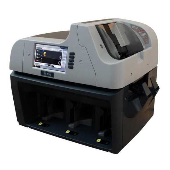
Page 4: Appearance
ST-350 Service Manual Appearance <Front View> Operation Button Touch Screen Hopper Speaker Reject Pocket Pocket 1 Display Pocket 2 Display Pocket 3 Display Pocket 3 Pocket 2 Pocket 1 Hitachi Terminal Solutions Korea Co., Ltd. - Page 5 <Rear View> Top Cover Release handle Front Release Button Handle Power Connector Power Switch DC Fan (Ethernet) USB A type USB B type RS232 External Video Out Serial Port Display Port (External Full Color LCD) Hitachi Terminal Solutions Korea Co., Ltd.
-
Page 6: Assemble & Disassemble
ST-350 Service Manual Assemble & Disassemble Deal Drawing Upper System Ass’y Lower System Ass’y Hitachi Terminal Solutions Korea Co., Ltd. - Page 7 Touch Screen and OS board are placed and shows all DISPLAY ASS'Y information to users. Hook operation lever for combining UPPER SYSTEM ASS’Y RELEASE LEVER ASS'Y and LOWER SYSTEM ASS’Y TOP COVER ASS'Y TOP COVER of machine. Hitachi Terminal Solutions Korea Co., Ltd.
- Page 8 Damper part when UPPER SYSTEM ASS'Y is open Center axis of combining UPPER SYSTEM ASS'Y and B-10 FRAME HINGE PLATE ASS'Y LOWER SYSTEM ASS'Y B-11 LOWER CASE ASS'Y External Cover of LOWER SYSTEM ASS'Y Hitachi Terminal Solutions Korea Co., Ltd.
- Page 9 Transfer the notes to POCKET 2, POCKET 3 and REJECT B-5h SORTING CAM 2 ASS'Y POCKET. B-5i SORTING CAM 3ASS'Y Transfer the notes to POCKET 3 and REJECT POCKET. B-5j TENSION UP BODY ASS'Y JAM SENSOR ASS'Y is included. Hitachi Terminal Solutions Korea Co., Ltd.
- Page 10 4. Go to Rear Side of machine and remove screw A Harness A Board A Harness B Harness C 5. Remove the cover from Machine. 6. Go to Rear Side of Machine and separate Harness A, B and from Board A Hitachi Terminal Solutions Korea Co., Ltd.
- Page 11 11. Remove Screw E. 12. Remove 3 harnesses very carefully. Belt A 13. Remove cover.. 14. Remove Belt A from Gears. Belt B 15. After remove Belt A. 16. Go to Front Side and remove Belt B. Hitachi Terminal Solutions Korea Co., Ltd.
- Page 12 18. Remove Screw F. Lever 5 Screw G 19. Go to Rear Side and remove Screw G. 20. Open Number 5 Lever. 21. After open Lever 5.. 22. Open MD Module by pushing Number 3 Lever. Hitachi Terminal Solutions Korea Co., Ltd.
- Page 13 ST-350 Service Manual 23. Grasp upper MD module and open lever 24. Remove MD Module from Machine. 25. The separated MD module. Hitachi Terminal Solutions Korea Co., Ltd.
- Page 14 4. Go to Rear Side of machine and remove screw A Harness A Board A Harness B Harness C 5. Remove the cover from Machine. 6. Go to Rear Side of Machine and separate Harness A, B and from Board A Hitachi Terminal Solutions Korea Co., Ltd.
- Page 15 10. Put Guide upper and lower Body and 9. Go to Area B and remove Screw B. remove it from Machine. 11. After remove Guide upper and lower 12. The separated Guide upper and lower Body. Body. Hitachi Terminal Solutions Korea Co., Ltd.
- Page 16 Screw A 3. Open B 4. Go to Rear Side of machine and remove screw A Screw B 5. Remove the cover from Machine. 6. Go to Front Side of machine and remove screw B. Hitachi Terminal Solutions Korea Co., Ltd.
- Page 17 10. Go to Rear Side of Machine and separate Harness A, B and from Board A Screw D – 7 pcs. Board A Rear Plate Board B 11. Remove Screw D from the machine. 12. Remove Rear Plate. Hitachi Terminal Solutions Korea Co., Ltd.
- Page 18 16. Removed Harnesses. Area A Area B 17. Pull out all removed harnesses and tie 18. To remove Hopper unit from Machine, you them together. have to remove screws from Area A and B. Hitachi Terminal Solutions Korea Co., Ltd.
- Page 19 19. Go to Area A and remove Screw A. 20. Go to Area A and remove Screw B. 21. Put Hopper unit and remove from 22. After remove Hopper unit. Machine. 23. The separated Hopper unit. Hitachi Terminal Solutions Korea Co., Ltd.
- Page 20 2. Remove Screw A. Cover A O/S Board 3. Remove Cover A. 4. O/S Board is shown. Harness A 5. Remove Harness A from O/S Board very 6. Separate O/S Board unit from Machine. carefully. Hitachi Terminal Solutions Korea Co., Ltd.
- Page 21 2. Pull Lever A and lift up upper side of Machine. Tension Body Screw A 3. Tension Body is shown. 4. Release Screw A slightly. Screw B Screw A 5. View in Screw A. 6. Remove Screw B. Hitachi Terminal Solutions Korea Co., Ltd.
- Page 22 9. Go to Left Side of Machine remove Screw 10. Remove Cover B. Screw D Screw E Cover C 11. Go to Reject Pocket and remove Screw 12. Go to Right of Machine remove Screw E. Hitachi Terminal Solutions Korea Co., Ltd.
- Page 23 15. Go to Area A and remove Belt A 16. Removed Belt A. Screw G Screw F 17. Go to Front Side of Machine and remove 18. Go to Rear Side of Machine and remove Screw F. Screw G. Hitachi Terminal Solutions Korea Co., Ltd.
- Page 24 19. Go to Front Side of Machine and remove 20. Go to Right Side of Machine and remove Screw H. Screw I. 21. Take Tension Body as the above picture. 22. Separate Tension Body from Machine. 23. After removed Tension Body. Hitachi Terminal Solutions Korea Co., Ltd.
- Page 25 2. Pull Lever A and lift up upper side of Machine. Tension Body Screw A 3. Tension Body is shown. 4. Release Screw A slightly. Screw B Screw A 5. View in Screw A. 6. Remove Screw B. Hitachi Terminal Solutions Korea Co., Ltd.
- Page 26 9. From left, Stacker 1, Stacker2, Stacker 3. 10. Remove Screw A from Stacker 1. Screw B- 7 pcs. Board B Rear Plate 11. Go to Rear Side. 12 Remove Rear Plate by removing Screw B. Hitachi Terminal Solutions Korea Co., Ltd.
- Page 27 15. After remove Stacker 1. 16. Remove Screw C from Stacker 2. Stacker 3 Stacker 2 Screw D 18. Remove Screw D from Stacker 3. 17. Remove Stacker 2 by pulling out with arrow direction. Hitachi Terminal Solutions Korea Co., Ltd.
- Page 28 ST-350 Service Manual Stacker 3 19. Remove Stacker 3 by pulling out with 20. After removing all Stackers. arrow direction. Hitachi Terminal Solutions Korea Co., Ltd.
- Page 29 3. Turn over MD module and remove 8 4. You can see a hole for fixing. screws. 5. Fix the hole by a thin screwdriver or a 6. Remove the TDS bolt. similar tool for removing TDS washer bolt easily. Hitachi Terminal Solutions Korea Co., Ltd.
- Page 30 8. Like the above picture, insert TDS Washer washer, you have to replace it with new one. to the screw. (New type: Middle section is stuck out.) 9. Assemble new type of TDS washer as this picture. Hitachi Terminal Solutions Korea Co., Ltd.
- Page 31 8. How to replace Upper Main Base. STEP 1. Disassemble GUIDE UPPER and LOWER BODY 1. Prepare the machine. 2. Open A. Screw A 3. Open B 4. Go to Rear Side of machine and remove screw A Screw B Hitachi Terminal Solutions Korea Co., Ltd.
- Page 32 10. Go to Rear Side of Machine and separate Harness A, B and from Board A Screw D – 7 pcs. Board A Rear Plate Board B 11. Remove Screw D from the machine. 12. Remove Rear Plate. Hitachi Terminal Solutions Korea Co., Ltd.
- Page 33 16. Removed Harnesses. Area A Area B 17. Pull out all removed harnesses and tie 18. To remove Hopper unit from Machine, you them together. have to remove screws from Area A and B. Hitachi Terminal Solutions Korea Co., Ltd.
- Page 34 19. Go to Area A and remove Screw A. 20. Go to Area A and remove Screw B. 21. Put Hopper unit and remove from 22. After remove Hopper unit. Machine. 23. The separated Hopper unit. Hitachi Terminal Solutions Korea Co., Ltd.
- Page 35 2. Go to Rear Side of Machine and separate Harness A, B and from Board A Screw E 3. Remove Screw E. 4. Remove 3 harnesses very carefully. Belt A 5. Remove cover.. 6. Remove Belt A from Gears. Hitachi Terminal Solutions Korea Co., Ltd.
- Page 36 8. Go to Front Side and remove Belt B. Screw F 9. After remove Belt B. 10. Remove Screw F. Lever 5 Screw G 11. Go to Rear Side and remove Screw G. 12. Open Number 5 Lever. Hitachi Terminal Solutions Korea Co., Ltd.
- Page 37 13. After open Lever 5.. 14. Open MD Module by pushing Number 3 Lever. 15. Grasp upper MD module and open lever 4 16. Remove MD Module from Machine. 17. The separated MD module. Hitachi Terminal Solutions Korea Co., Ltd.
- Page 38 4. Go to Area A and remove Screw A. screws from Area A and Area B.. Screw B 6. Put Guide upper and lower Body and 5. Go to Area B and remove Screw B. remove it from Machine. Hitachi Terminal Solutions Korea Co., Ltd.
- Page 39 7. After remove Guide upper and lower Body. 8. The separated Guide upper and lower Body. STEP 4. Disassemble ETC. 2. Close the cover and remove the TOP 1. Remove 6 screws. COVER. 3. Remove 2 screws and ROOF COVER PLATE. Hitachi Terminal Solutions Korea Co., Ltd.
- Page 40 ST-350 Service Manual 5. Remove ROOF SHAFT and ROOF 4. Remove E-ring from left and right side. SPRING. 6. After remove 3 screws, remove ROOF BRACKET. 7. Remove screws. Hitachi Terminal Solutions Korea Co., Ltd.
- Page 41 Harness from Board A.(Main Board) RELEASE LEVER BRACKET 11. Remove screws from USB PLATE. 10. Go to Rear and Lower Side of Machine. 12. Remove harnesses from PERIPHERAL 13. Remove POWER 1 HARNESS from BOARD ASS'Y SMPS. Hitachi Terminal Solutions Korea Co., Ltd.
- Page 42 ST-350 Service Manual 14. Go to Upper Main Base. 15. Remove 2 screws. 16. Go to DISPLAY ASS'Y. 17. Remove 4 screws. Harness 18. After raise A, remove DISPLAY ASS'Y. 19. Remove screws. (With harness) Hitachi Terminal Solutions Korea Co., Ltd.
- Page 43 21. Remove screws. 20. Remove screws from down side. 23 Go to OPEN SWITCH ASS'Y of Top 22. Remove RELEASE LEVER ASS'Y. Cover. 25. Remove screw. 24. After remove harness and screws, remove OPEN SWITCH ASS'Y Hitachi Terminal Solutions Korea Co., Ltd.
- Page 44 Main Board 27. Remove screws. 26. Go to MAIN BOARD ASS'Y. 28. After remove screw, remove MAIN BOARD ASS'Y 29. After remove screws, remove LCD 30. After remove screws, remove LCD COVER MAGNET COVER MAGNET Hitachi Terminal Solutions Korea Co., Ltd.
- Page 45 ST-350 Service Manual 31. Remove left and right cover. 32. Remove it. (left and right side) Hitachi Terminal Solutions Korea Co., Ltd.
- Page 46 34. Remove E-ring. (Both side) 35. Put the driver next to Shaft 36. Hit the driver several times until the shaft 37. Remove UPPER BASE PLATE ASS'Y. disassembled. 38. Assemble all parts in reverse orders. Hitachi Terminal Solutions Korea Co., Ltd.
- Page 47 2. Pull Lever A and lift up upper side of Machine. Tension Body Screw A 3. Tension Body is shown. 4. Release Screw A slightly. Screw B Screw A 5. View in Screw A. 6. Remove Screw B. Hitachi Terminal Solutions Korea Co., Ltd.
- Page 48 9. Go to Left Side of Machine remove Screw 10. Remove Cover B. Screw D Screw E Cover C 11. Go to Reject Pocket and remove Screw 12. Go to Right of Machine remove Screw E. Hitachi Terminal Solutions Korea Co., Ltd.
- Page 49 15. Go to Area A and remove Belt A 16. Removed Belt A. Screw G Screw F 17. Go to Front Side of Machine and remove 18. Go to Rear Side of Machine and remove Screw F. Screw G. Hitachi Terminal Solutions Korea Co., Ltd.
- Page 50 19. Go to Front Side of Machine and remove 20. Go to Right Side of Machine and remove Screw H. Screw I. 21. Take Tension Body as the above picture. 22. Separate Tension Body from Machine. Hitachi Terminal Solutions Korea Co., Ltd.
- Page 51 1) Sorting Sliding Shaft 1 and 3 23. Remove 3 plates. 24. 2 Yellow boxes are Sorting sliding Shaft 1. 25. Yellow box is Sorting sliding Shaft 3. 26. Remove 3 screws. 27. Remove Solenoid. 28. Remove Belt. Hitachi Terminal Solutions Korea Co., Ltd.
- Page 52 30. After remove E-ring, PULLEY and SPRING. Shaft 3 Shaft 1 31. Go to the opposite side. 32. Remove E-ring, PULLEY and SPRING. 33. After Remove E-ring, PULLEY and 34. Remove Sorting Sliding Shaft 1,3. SPRING. Disassembly is finish. Hitachi Terminal Solutions Korea Co., Ltd.
- Page 53 ST-350 Service Manual When you assemble Sorting Sliding 35. When you assemble Shaft, you do Shaft, you have to check the Left and assembly in reverse order. Right side as like picture. Hitachi Terminal Solutions Korea Co., Ltd.
- Page 54 ST-350 Service Manual 2) Sorting Sliding Shaft 2 1. Remove 3 plates. 2. Remove Belt and remove E-ring. FLAT WASHER SPRING FLAT WASHER, SPRING and 3. Remove PULLEY Sorting Sliding Shaft 2. 4. Remove Hitachi Terminal Solutions Korea Co., Ltd.
-
Page 55: Data Acquisition
<FR direction> <BF direction> <BR direction> And you have to inform the direction to the saved files. Because the data is saved to a folder, please mark the direction to folder name as below. Hitachi Terminal Solutions Korea Co., Ltd. - Page 56 ST-350 Service Manual 1. Turn on the machine. 2. Click Menu. 3. Click Machine Setting. Hitachi Terminal Solutions Korea Co., Ltd.
- Page 57 ST-350 Service Manual 4. Enter Pincode “0000”. 5. Click “Data Acquisition” Hitachi Terminal Solutions Korea Co., Ltd.
- Page 58 ST-350 Service Manual 6. Insert USB Stick. 7. Put a note which you need to save data on the Hopper. 8. >> [All Data for CIS Image T/B and IR] → Touch “Click”. Hitachi Terminal Solutions Korea Co., Ltd.
- Page 59 ST-350 Service Manual 9. UV data is saved first. 10. MG data is saved. Hitachi Terminal Solutions Korea Co., Ltd.
- Page 60 ST-350 Service Manual 11. TDS data is saved. 12. FULL0 data is saved. Hitachi Terminal Solutions Korea Co., Ltd.
- Page 61 ST-350 Service Manual 13. FULL1 data is saved. 14. FULL2 data is saved. Hitachi Terminal Solutions Korea Co., Ltd.
- Page 62 ST-350 Service Manual 15. Sensor Information is saved. 16. You can check the saved data from USB Stick. A folder is creased with date and time. Hitachi Terminal Solutions Korea Co., Ltd.
- Page 63 ST-350 Service Manual 17. When enter the folder, 9 kinds of data are created. 18. Send all files to us. Hitachi Terminal Solutions Korea Co., Ltd.
-
Page 64: Upgrade & Calibration
2) Make Upgrade folder and copy upgrade file Ex) G:\Upgrade (if you modify name like upgrade1 or others, it does not work) 3) Insert USB memory stick to machine 4) Go to Menu 5) Click Upgrade. Hitachi Terminal Solutions Korea Co., Ltd. - Page 65 ST-350 Service Manual 6) Enter Pincode (Initial Pincode is” 0000”). 7) Upgrade screen is shown. ( Each part S/W is hooked up to upgrade file ) Hitachi Terminal Solutions Korea Co., Ltd.
- Page 66 APP Upgrade Part : It Takes about 5 minutes 9) Click Start icon. 10) When upgrade is complete, turn off Machine manually. 11) Remove USB Stick from Machine. 12) Turn on machine again. 13) Check Software version. Hitachi Terminal Solutions Korea Co., Ltd.
- Page 67 1) Connect Machine to PC via cross LAN Cable. 2) After connecting, set IP address of PC manually. Available IP address: 192.168.10.100~250 3) By pressing Currency, Display and Start/Clear key together, turn on the machine. Hitachi Terminal Solutions Korea Co., Ltd.
- Page 68 OS Software is closely related with Main and APP software. After upgrade Software, you need to upgrade Main and APP software! Before upgrade OS Software, please contact us first. (important!) 6) Execute Upgrade.exe 7) Load NK.bin which is placed in the same folder. Hitachi Terminal Solutions Korea Co., Ltd.
- Page 69 2) Copy Upgrade folder to USB Sick and turn on the machine. 3) Enter Upgrade menu. 4) When you enter Upgrade menu, two items are added. If NK2_1.SOB file is existed in Upgrade folder, two items are shown together. Hitachi Terminal Solutions Korea Co., Ltd.
- Page 70 ST-350 Service Manual 5) Select OS Image Upgrade and click “Start” icon. 6) After complete, reboot the machine. 7) Check OS version is changed to Core [2.1]. Hitachi Terminal Solutions Korea Co., Ltd.
- Page 71 ST-350 Service Manual 3. Calibration Setting Paper TDS & CIS Setting Paper (10 sheets) CIS Setting Paper 1- IR Transmission Setting Paper (1 sheet) CIS Setting Paper 2- Visible Reflection Setting Paper (5 sheets) Hitachi Terminal Solutions Korea Co., Ltd.
- Page 72 ST-350 Service Manual 1) Go to Menu 2) Go to Machine Setting. Hitachi Terminal Solutions Korea Co., Ltd.
- Page 73 ST-350 Service Manual 3) Enter Pincode (Initial Pincode is” 0000”). Hitachi Terminal Solutions Korea Co., Ltd.
- Page 74 4) Counter Sensor Calibration ① Click Counter Sensor. ② Counter Sensor Setting screen is as below. ③ Click “Internal Counter Sensor Setting” ④ When finish the Setting successfully, “Success” message is shown with Green. Hitachi Terminal Solutions Korea Co., Ltd.
- Page 75 ③ Click “UV Offset Setting” and setting is completed automatically. ④ When finish UV Offset Setting successfully, “Success” message is shown with Green. UV Offset setting value of L channels must be 100 ~ 150 Hitachi Terminal Solutions Korea Co., Ltd.
- Page 76 ST-350 Service Manual ⑤ Click “UV Gain Setting” ⑥ When finish UV Gain Setting successfully, “Success” message is shown with Green. UV Gain setting value must be 50 ~ 220 Hitachi Terminal Solutions Korea Co., Ltd.
- Page 77 TDS Offset value of 12 channels must be 60 ~ 200 Also, except the between Ch.1 and Ch.2 & between Ch.11 and Ch.12 value, Do not over 50 between the value and both sides. Hitachi Terminal Solutions Korea Co., Ltd.
- Page 78 ST-350 Service Manual ⑤ Put 10 TDS Setting Papers with new one on Hopper.(Important) ⑥ Click “TDS Soft Gain Setting”. Hitachi Terminal Solutions Korea Co., Ltd.
- Page 79 ⑦ Machine counts Papers and setting is completed. Except the first and the last channel value, TDS Gain value of 10 channels must be 0.6 ~ 2.0 ⑧ S hould be that It was done right TDS Setting on the page2 Hitachi Terminal Solutions Korea Co., Ltd.
- Page 80 ST-350 Service Manual ⑨ Put 1 TDS Setting Paper on Hopper. ⑩ Click “TDS Acquisition Data Information”. Hitachi Terminal Solutions Korea Co., Ltd.
- Page 81 Except the first and the last channel value, TDS Paper Normal value of 10 channels must be 115 ~ 125 If values are not in 115~125, return to step 9 and repeat again by using another white paper. Nevertheless, these values are not in 115~125, return to step 5 and repeat again. Hitachi Terminal Solutions Korea Co., Ltd.
- Page 82 ST-350 Service Manual 7) Motor Calibration ① Click Motor. ② Motor Setting screen is as below. ③ Click “Motor Speed All Setting”. ④ When finish the Setting successfully, “Success” message is shown with Green. Hitachi Terminal Solutions Korea Co., Ltd.
- Page 83 ST-350 Service Manual 8) CIS Calibration 1) Go to Menu. 2) Click Machine Setting. Hitachi Terminal Solutions Korea Co., Ltd.
- Page 84 ST-350 Service Manual 3) Enter Pincode “0000”. 4) Click “CIS”. Hitachi Terminal Solutions Korea Co., Ltd.
- Page 85 ST-350 Service Manual 5) Click the message screen. *STEP 1. Auto Mode Setting 1) Open MD Module and check CIS sensor. Hitachi Terminal Solutions Korea Co., Ltd.
- Page 86 ST-350 Service Manual 2) Put IR setting paper on CIS sensor, rough side uppermost. (One side of IR setting paper is rough and the other is smooth.) 3) Close MD Module. Hitachi Terminal Solutions Korea Co., Ltd.
- Page 87 ST-350 Service Manual 4) Start IR CIS setting by pressing “Click” as below. 5) When the setting is completed, “Success” message is shown with beep. Hitachi Terminal Solutions Korea Co., Ltd.
- Page 88 ST-350 Service Manual 6) Remove IR setting paper from the sensor and close MD Module. 7) Open MD Module and put 5 sheets of CIS setting paper on the sensor. Hitachi Terminal Solutions Korea Co., Ltd.
- Page 89 ST-350 Service Manual 8) Close MD Module. 9) Press “Click” of Top CIS Sensor. (Approximately, a minute is needed for completing.) Hitachi Terminal Solutions Korea Co., Ltd.
- Page 90 ST-350 Service Manual 10) When complete, “Success” message is shown as below. 11) Open MD Module and put a sheet of CIS setting paper on the sensor. Hitachi Terminal Solutions Korea Co., Ltd.
- Page 91 ST-350 Service Manual 12) Close MD Module. 13) Press “Click” of Bottom CIS Sensor. (Approximately, one-and-a-half minutes are needed for completing.) Hitachi Terminal Solutions Korea Co., Ltd.
- Page 92 ST-350 Service Manual 14) When complete, “Success” message is shown as below. 15) Open MD Module and remove CIS setting paper from the sensor. Hitachi Terminal Solutions Korea Co., Ltd.
- Page 93 ST-350 Service Manual 16) Close MD Module. *STEP 2. Outline Offset Setting 1) Go to next page by pressing the arrow. Hitachi Terminal Solutions Korea Co., Ltd.
- Page 94 ST-350 Service Manual 2) The second page is as below. 3) Put 5 papers of Outline setting paper on the Hopper. Hitachi Terminal Solutions Korea Co., Ltd.
- Page 95 ST-350 Service Manual 4) Click “Motor Run” as below. 5) Machine counts the setting paper. If the calibration is complete, “Done” message is shown. Hitachi Terminal Solutions Korea Co., Ltd.
- Page 96 ST-350 Service Manual 24) Click “Outline Offset Save” as below. 25) “Complete” message is shown and the calibration is finished. Hitachi Terminal Solutions Korea Co., Ltd.
- Page 97 *STEP 3. Check Setting Values for CIS TOP, BOTTOM and IR STEP 3-1. How to check Top CIS Setting Value 1) Go to page 2 by pressing the arrow. 2) The second page is as below. Hitachi Terminal Solutions Korea Co., Ltd.
- Page 98 ST-350 Service Manual 3) Click “Setting Outline Offset”. 4) Display is changed as below. Hitachi Terminal Solutions Korea Co., Ltd.
- Page 99 ST-350 Service Manual 5) Put 10 papers of Outline setting paper on Hopper. 6) Click “Motor Run”. Hitachi Terminal Solutions Korea Co., Ltd.
- Page 100 Except the first and the last channel value, the average value of 10 channels must be 233 ~ 235. If these values are higher or lower than 233~235 as above, you have to adjust the value manually. (STEP 4) Hitachi Terminal Solutions Korea Co., Ltd.
- Page 101 ST-350 Service Manual STEP 3-2. How to check Bottom CIS Setting Value 8) Change White Adjust Status : BOTTOM Values 9) Put 10 papers of Outline setting paper on Hopper. Hitachi Terminal Solutions Korea Co., Ltd.
- Page 102 10) Click “Motor Run”. 11) The paper is counted and the pixel data of CIS Sensor Bottom is shown. If the values are OK, the numbers are green. If out of range, they are red as above. Hitachi Terminal Solutions Korea Co., Ltd.
- Page 103 If these values are higher or lower than 233~235 as above, you have to adjust the value manually. (STEP 4) STEP 3-3. How to check IR setting Value 12) Change “White Adjust Status: IR”. Hitachi Terminal Solutions Korea Co., Ltd.
- Page 104 ST-350 Service Manual 13) Put 10 papers of Outline setting paper on Hopper. 14) Click “Motor Run”. Hitachi Terminal Solutions Korea Co., Ltd.
- Page 105 Except the first and the last channel value, the average value of 10 channels must be 70 ~ 90. If these values are close to 80, it is good condition. If these values are higher or lower than 70~90 as above, you have to adjust the value manually. (STEP 4) Hitachi Terminal Solutions Korea Co., Ltd.
- Page 106 If the values are little high or low, you can adjust them in Gain ADJ Mode. (STEP 4-2) After adjust the values in Gain ADJ Mode, you don’t need to do STEP 1 Auto Mode Setting. STEP 4-1. Manual Mode 1) Go to “page1”. Hitachi Terminal Solutions Korea Co., Ltd.
- Page 107 ST-350 Service Manual 2) Click “COEF ADJUST” icon. 3) Display is shown as below. Hitachi Terminal Solutions Korea Co., Ltd.
- Page 108 The checked CIS TOP values are higher than 235, decrease the values by clicking < -- >. The checked CIS Bottom values are lower than 235, increase the values by clicking < ++ >. The checked IR values are higher than 80, decrease the values by clicking < -- >. Hitachi Terminal Solutions Korea Co., Ltd.
- Page 109 ST-350 Service Manual 6) After change the values, click “Save and Exit”. Hitachi Terminal Solutions Korea Co., Ltd.
- Page 110 ST-350 Service Manual 7) Go to STEP 1 and repeat Auto Mode Setting. 8) After setting is completed, check Setting Values for CIS TOP, BOTTOM and IR (STEP 3). The values are changed as below Hitachi Terminal Solutions Korea Co., Ltd.
- Page 111 If the values are little high or low, you can adjust them in this mode. After adjust the values in Gain ADJ Mode, you don’t need to do STEP 1 Auto Mode Setting. 1) Go to “page1”. Hitachi Terminal Solutions Korea Co., Ltd.
- Page 112 ST-350 Service Manual 2) Click “COEF ADJUST” icon. 3) Display is shown as below. Hitachi Terminal Solutions Korea Co., Ltd.
- Page 113 ST-350 Service Manual 4) Click “Auto Mode” twice and “Gain ADJ Mode” is selected. 5) Increase or decrease IR, CIS TOP and CIS Bottom Values slightly. Hitachi Terminal Solutions Korea Co., Ltd.
- Page 114 ST-350 Service Manual 6) After change the values, click “Save and Exit” 7) Check Setting Values for CIS TOP, BOTTOM and IR (STEP 3). The values are changed as below. Hitachi Terminal Solutions Korea Co., Ltd.
- Page 115 ST-350 Service Manual Hitachi Terminal Solutions Korea Co., Ltd.
-
Page 116: Machine Setting Menu
ST-350 Service Manual Machine Setting Menu (Pin-code is needed) 1. Fitness Menu 1) Click “Fitness”. Hitachi Terminal Solutions Korea Co., Ltd. - Page 117 ST-350 Service Manual 2) Select country. 3) If you want to change Dog-Ear Fit Level, Click the percentage. Hitachi Terminal Solutions Korea Co., Ltd.
- Page 118 ST-350 Service Manual 4) Input the new Dog-Ear Fit Level. 5) Input the 70. (For example) Hitachi Terminal Solutions Korea Co., Ltd.
- Page 119 ST-350 Service Manual 6) The Dog-Ear Fit Level is changed to 70% 7) If you want to ignore Tear condition, turn off the green light by pressing it. Hitachi Terminal Solutions Korea Co., Ltd.
- Page 120 ST-350 Service Manual 2. Currency Menu 1) Click “Currency”. 2) Select country. Hitachi Terminal Solutions Korea Co., Ltd.
- Page 121 ST-350 Service Manual 3) If you want to change UV Level, Click the percentage. 4) Input the new UV Level. Hitachi Terminal Solutions Korea Co., Ltd.
- Page 122 ST-350 Service Manual 5) Input the 80. (For example) 6) The UV Level is changed to 80% Hitachi Terminal Solutions Korea Co., Ltd.
- Page 123 ST-350 Service Manual 8) If you want to ignore MG condition, turn off green light by pressing here it. 3. Mode Menu 1) Click “Mode”. Hitachi Terminal Solutions Korea Co., Ltd.
- Page 124 ST-350 Service Manual 2) Select country. 3) This is menu now in use. Hitachi Terminal Solutions Korea Co., Ltd.
- Page 125 ST-350 Service Manual 4) You can change using or not using menus by pressing the items. 4. Select Unfit Pocket Menu 1) Click “Select Unfit Pocket”. Hitachi Terminal Solutions Korea Co., Ltd.
- Page 126 ST-350 Service Manual 2) Select country. 3) This is the emission condition on Fitness Mode now in use. (Pocket3 or Reject Pocket) Hitachi Terminal Solutions Korea Co., Ltd.
- Page 127 ST-350 Service Manual 4) You can change position of emission to Pocket3 or Reject Pocket by pressing select mark in a yellow circle. Hitachi Terminal Solutions Korea Co., Ltd.
-
Page 128: Maintenance
Refer to following section and clean the machine regularly. ※ Please turn the power off before cleaning the machine. Upper Body Main Body Upper Body Open Upper Body. Up Tension Body Down Tension Body Open Up Tension Body. Clean Dowm Tension Body. Hitachi Terminal Solutions Korea Co., Ltd. - Page 129 ST-350 Service Manual Front Cover Open Front Cover. Top Cover Open Top Cover. MD Module Open MD Module. Clean Lower MD Housing. Lower MD Housing Hitachi Terminal Solutions Korea Co., Ltd.
- Page 130 ST-350 Service Manual Upper MD Housing Clean Upper MD Housing. INT Tension Body Clean INT Tension Body. Hitachi Terminal Solutions Korea Co., Ltd.
- Page 131 ST-350 Service Manual Guide Upper Body Guide Lower Body Clean Guide Upper and Lowr Body. Reject Pocket Stacker Sensor Main Pocket Clean Stacker Sensor of each Main Pocket. Hitachi Terminal Solutions Korea Co., Ltd.
- Page 132 ST-350 Service Manual Reject Pocket Reject Pocket Counter Sensor Clean Reject Pocket Counter Sensor. Hitachi Terminal Solutions Korea Co., Ltd.
- Page 133 1. UPPER BASE PLATE ASSEMBLY When remove Bite Main Frame Assembly, MD Module Assembly and Guide Body Assembly, dust is stacked on Upper Base Plate Assembly. 1) Remove Bite Main Frame Assembly. 2) Remove MD Module Assembly. Hitachi Terminal Solutions Korea Co., Ltd.
- Page 134 ST-350 Service Manual 3) Remove Guide Body Assembly. Clean Upper Base Plate assembly with a vacuum. 2. TOP MD MODULE Assembly 1) After remove MD Cover Plate, clean A with a brush. Hitachi Terminal Solutions Korea Co., Ltd.
- Page 135 2) Remove DM Board and DM Plate. 3) Remove screws from TDS assembly. ******Very important Note***** Don’t open TDS board from body. If you open this board, you should be returned this assembly to factory for adjustment. Hitachi Terminal Solutions Korea Co., Ltd.
- Page 136 ST-350 Service Manual ******Very important Note***** TDS Rollers must not be stabbed! When you clean this area, please be careful. 4) Separate TDS assembly from MD Module and clean the gaps with a brush. Hitachi Terminal Solutions Korea Co., Ltd.
- Page 137 ST-350 Service Manual 3. BOTTOM MD MODULE Assembly 1) Remove MD Bottom Plate. MD Bottom Plate 2) Remove TDS Dust Bar Assembly. Hitachi Terminal Solutions Korea Co., Ltd.
- Page 138 ST-350 Service Manual 3) Clean TDS Dust Bar with a brush. 4) Clean TDS Roller, MG Brush and MD Roller with a brush. Hitachi Terminal Solutions Korea Co., Ltd.
- Page 139 ST-350 Service Manual 4. SORTING UP/DOWN Assembly 1) Clean Top Body Cover with a vacuum. 2) Clean the dust on Body Frame and Pulleys with a brush. Hitachi Terminal Solutions Korea Co., Ltd.
- Page 140 ST-350 Service Manual 5. MAIN BODY Assembly Clean corners of Main Body with a brush or a vacuum. Hitachi Terminal Solutions Korea Co., Ltd.
-
Page 141: Others
100 ~ 240V AC, 50/60Hz Hopper 600 notes Capacities Stacker x 3 200 notes Reject Pocket 100 notes Piece Counting 1,000 notes/min Value Counting 1,000 notes/min Operation Speed Fitness Sorting 700 notes/min Serial Number Print Out 500 notes/min Hitachi Terminal Solutions Korea Co., Ltd. -
Page 142: Trouble Shootings
Communication Error caused among the boards. boards operation. 2 notes are inserted together. Check GAP is wide or Double Error not. Communication problems are Check harness between Communication Error caused among the boards. boards operation. Hitachi Terminal Solutions Korea Co., Ltd. - Page 143 Both side serial numbers are different. Change Serial Number DEFAULT Err-Main15 Image distortion is caused Check scanned Skew Error from DM B/D. image from D/M B/D. scanned image different from genuine note. Value Error Hitachi Terminal Solutions Korea Co., Ltd.
- Page 144 The scanned IR data is Check IR image data different from genuine note. which is from DM B/D IR Error Different Serial Both side serial numbers are Check serial different. numbers. Change Serial Number DEFAULT Err-DM34 Hitachi Terminal Solutions Korea Co., Ltd.
- Page 145 DogEar Hole Composed Multitation DEFAULT Err-DM35 Soil, Deinked, Crumple The note is out of range of ATM or FIT. Soil, Deinked Soil, Crumple Deinked, Crumple Soil Deinked Deinked, Mark Crumple Stain Graffiti DEFAULT Err-DM36 Hitachi Terminal Solutions Korea Co., Ltd.
- Page 146 Main Internal Counter Sensor Pocket3 Right Main Internal Counter Sensor Pocket3 Verify Main Internal Counter Sensor Reject Center 1. Calibrate Motor again. Main Solenoid 1 2. Check harnesses. Main Solenoid 2 3. Replace the related board. Main Solenoid 3 Hitachi Terminal Solutions Korea Co., Ltd.
- Page 147 DM SystemFlag 1. After cleaning, calibrate CIS. DM CIS Top Dirt 2. Check harnesses. DM CIS Bottom Dirt 3. Replace the related board. DM CIS IR Setting DM CIS Top Setting DM CIS Bottom Setting Hitachi Terminal Solutions Korea Co., Ltd.
- Page 148 ==> Ok : Re Connect Error Case 4 <== SendMessage_Ready ==> IS READY Error Case 5 <== SendMessage_Erase :A==> Send ==> ERASE <== SendMessage_Erase :B==> Send ==> ERASE <== SendMessage_Erase :C==> Send ==> ERASE <== SendMessage_Erase :D==> Send Hitachi Terminal Solutions Korea Co., Ltd.
- Page 149 Error Case 9 <== SendMessage_HexDataEnd ==> End Hex File Error Case 10 ==> SEND HEX ---- End Error Case 11 ==> STEP_FINISH ==> Main DisConnect ==> File Check ..Ok ==> End Upgrade ReBoot Machine Hitachi Terminal Solutions Korea Co., Ltd.
- Page 150 2. When “Restart” is shown repeatedly, change Upgrade SMH file. If “Restart” message is shown this, there is no response about the ending Error Case 10 SMB. 1. Restart the machine. 2. When “Restart” is shown repeatedly, change Upgrade SMH file. Hitachi Terminal Solutions Korea Co., Ltd.
Need help?
Do you have a question about the ST-350 and is the answer not in the manual?
Questions and answers