SOLIS 5G Series User Manual
Hide thumbs
Also See for 5G Series:
- Instruction manual (39 pages) ,
- User manual (84 pages) ,
- Installation manual

Subscribe to Our Youtube Channel
Related Manuals for SOLIS 5G Series


Summary of Contents for SOLIS 5G Series
- Page 1 User Manual Solis Export Power Manager 5G Series Applicable Models: Solis-EPM3-5G-PRO Version 1.1 Release Date: 08/29/2023...
- Page 2 ● Solis accepts no liability for customers' failure to comply with the instructions for correct installation and will not be held responsible for upstream or downstream systems Solis equipment has supplied.
- Page 3 Table of Contents Introduction Safety Overview Installation Comissioning & Decommissioning Operation Troubleshooting Tehnical Specs Appendices...
-
Page 4: Table Of Contents
Table of Contents 1. Introduction ……… …… ……… ……… ……… ……… …………………………… ………… ……… ……… …… … … 1.1 Product Description …… ………… ……… ……… …… … …… … …… ……… ……… ……… ………… ………… 1.2 Packaging …… ……… …… … …… ……… ……… ………… ……… ……… …… ……… ……… ……… ……… ……… 2. - Page 5 Table of Contents 6.4 Advanced Info - Technicians Only … … … … …… … … … … …… … … …… … …… … … … … … 6.4.1 Inverter Power … …… … … … … …… … … …… ……… … … … … …… … … …… …… … … …… …… … … …… … 6.4.2 CT Connection Status …...
-
Page 6: Introduction
1. Introduction 1.1 Product Description Solis 5G Series Export Power Manager can monitor and control the backflow power from the inverter to the grid thus providing export power control of inverters. The export power manager is suitable for use with all solar PV grid tie inverters. -
Page 7: Packaging
EPM x1 RS485 cable x1 Meter x1 RS485 cable x5 5 core AC connector x1 (10m for meter connection) (only for EPM3-5G-PRO) (Inverter RS485 terminal x5 pcs) Manual User manual x1 If anything is missing, please contact your local Solis distributor. -
Page 8: Safety
2. Safety 2.1 Safety Symbols Safety symbols used in this manual, which highlight potential safety risks and important safety information, are listed as follows: WARNING: WARNING symbol indicates important safety instructions, which if not correctly followed, could result in serious injury or death. NOTE: NOTE symbol indicates important safety instructions, which if not correctly followed, could result in some damage or the destruction of the inverter. -
Page 9: Notice For Use
2. Safety 2.3 Notice For Use The Export Power Manager has been constructed according to the applicable safety and technical guidelines. Use the Export Device in installations that meet the following specification ONLY: 1. Permanent installation is required 2. The electrical installation must all the applicable regulations and standards. 3. -
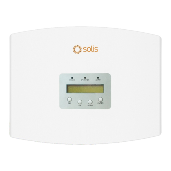
Page 10: Overview
3. Overview 3.1 Front Panel Display Figure 3.1 Front Panel Display 3.2 LED Status Indicator Lights Description Light Status Export Device power on POWER Export Device power off Communication with inverter OPERATION No communication with inverter Alarm ALARM No alarm Table 3.1 Status Indicator Lights 3.3 Keypad There are four keys in the front panel of the Inverter(from left to right):... -
Page 11: Installation
4.Installation 4.1 Select a Location for the EPM To select a location for the EPM, the following criteria should be considered: The temperature of the EPM could up to 75 C. The EPM is designed to work in extreme temperature range is from -25 C to 60 C. The EPM should be kept minimum 300mm clearance from the other device. - Page 12 4.Installation Hang the EPM in the bracket by the steps below .(see Figure 4.3) Figure 4.3 Hang the EPM in the bracket Fix the two screw at the side of bracket.(see Figure 4.4) M4 locking screw M4 locking screw Figure 4.4 Fix the two screw...
-
Page 13: Electrical Connections
AC voltage sampling terminal Meter Connect to Meter RS485 interface Comm_INV Connect to solis inverters Communication Monitoring device or Upgrade Stick Table 4.1 The meaning of the symbols located at bottom of the EPM System connection diagram is as follows:... -
Page 14: Making The Grid Input Cable
Measure the distance from EPM to power distribution box. And find proper cable for grid input. Use 5 core cable for Solis EPM3-5G-PRO. b. Connect L1, L2, L3, N and PE to pins 1, 2,3, N and PE. (see figure 4.8). - Page 15 4.Installation d. Strip the end of cable to 3mm. Cross-section 1.5mm² x=3mm Figure 4.8 Strip the cable(Three Phase) e. Through the cable to the washer and use a suitable screw driver to fix the wire to the connector. φ9.5mm~φ11.5mm Figure 4.9 Welding wire to connector(Three Phase) f.
-
Page 16: Making The Rs485 Cable (Comm-Inc Port)
4.Installation 4.3.2 Make RS485 cable(COMM-INV port) a. Refer to figure 4.16, the RS485 terminals for inverter and EPM are already assembled. Tips:RS485 cable: preferred 0.5mm², max 1.0mm². + to connect RS485 A φ25.5 - to connect RS485 B Figure 4.11 RS485 terminal b. -
Page 17: Meter Connections (Only For Epm3-5G-Pro)
4.Installation 4.3.3 Meter connection (only for EPM3-5G-PRO) Connection between EPM and meter EPM3-5G-PRO needs to connect to the RS485 communication of the meter to read and display the power, voltage, and current data on the grid side. Pre-made Cable in Meter Package 21 22 17 1819 20 UaUb Uc N Ia* Ia Ib* Ib Ic* Ic 2-Pin Connector... - Page 18 4.Installation 1.2 Meter Specification Specification 3 phase 3 wires, 3 phase 4 wires Reference voltage 3-110V, 3-400V, 3-480V, 3-66/115V, 3-230/400V, 3-277/480V Input voltage fluctuation 0-120% <10VA(Single phase) Voltage Consumption >2MΩ Impedance Accuracy class Error±0.2% Input current 3-1(6)A <1VA(Single phase rated current) Consumption Current Accuracy class...
-
Page 19: Connecting And Fixing The Ct
4.Installation Figure 4.16 Three phase four lines connect via CT 4.3.4 Connect and fix the CT To detect the backflow power, the CTs need to be installed at the PCC (Point of Common Coupling), instead of the load branch circuit. NOTE: For three phase system, CT must be installed on U,V and W with correct sequence, otherwise EPM can not detect the correct data. -
Page 20: Multi Inverter Connection
EPM devices and inverters. Solis can also provide above current transformers as an optional accessory. Customers can contact Solis sales rep to place the order based on their project requirements. 4.3.5 Multi-inverter connection Please follow the previous system diagrams to connect multiple inverters. -
Page 21: Commissioning And Decommissioning
5.Comissioning and Decommissioning 5.1 Commissioning 1. Switch off all the AC breakers and DC breakers in the system. 2. Complete AC and DC wirings for inverters by following inverter manuals. 3. Connect AC cables to the Grid terminal on the EPM. 4. -
Page 22: Operation
2. Settings 3. Advanced Info. 4. Advanced Settings 6.2 Information Solis Export Power Manager main menu provides access to operational data and information. The information is displayed by selecting "Information" from the menu and then by scrolling up or down. -
Page 23: Lock Screen
6. Operation Display Description VacA_Grid: 000.0V IacA_Grid: 000.0A VacB_Grid: 000.0V Vac_Grid: Grid voltage and current. IacB_Grid: 000.0A VacC_Grid: 000.0V IacC_Grid: 000.0A Load_Pwr: Load Power. Load_Pwr: 0000.0KW Total_PINV: 0000.0KW Total_PINV: Total output power of inverters. Export Limited: Inverter output power percentage. Export Limited: 000% Frequency:... -
Page 24: Settings
6. Operation 6.3 Settings The following submenus are displayed when the Settings menu is selected: 1. Set Time 2. Set Address 6.3.1 Set Time This function allows time and date setting. When this function is selected, the LCD will display a screen as shown in Figure 6.3. NEXT=<ENT>... -
Page 25: Advanced Info - Technicians Only
6. Operation 6.4 Advanced Info - Technicians Only NOTE: To access to this area is for fully qualified and accredited technicians only. Enter menu “Advanced Info.” and “Advanced settings” (need password). Select “Advanced Info.” from the Main Menu. The screen will require the password as below: YES=<ENT>... -
Page 26: Version
6. Operation 6.4.3 Version The screen shows the model version and the software version of the Inverter. Software Ver.: 11 Figure 6.8 Version 6.4.4 Model Inverter The screen shows the Rated power of inverters that are connected to the EPM. Model: 50000 Figure 6.9 Model Inverter... -
Page 27: Inverter Quantity Set
6. Operation NOTE: To access to this area is for fully qualified and accredited technicians only. Please follow 6.4 to enter password to access this menu. Select Advanced Settings from the Main Menu to access the following options: 1. Inverter Qty. Set 2. Backflow Power 3. Set CT Ratio 4. FailSafe ON/OFF 5. -
Page 28: Setting The Ct Ratio
6. Operation 6.5.3 Set CT Ratio This is used to set the CT ratio for the current transformer. Setting range is from 20:1 to 9900:1 with 10:1 interval. For example, if 1000:5A current transformer is used, please set the ratio as 200:1 YES=<ENT>... - Page 29 6. Operation Mode “01”, As shown in the figure 6.17, the average limiting mode, the output power of each phase is the average of the three-phase load power, and it is more than the phase of the lowest power in three phases. Inverter Figure 6.17 Mode “02”, as shown in the figure 6.18 the per phase limiting mode, the inverter only...
-
Page 30: Transmit On/Off
6. Operation 6.5.6 Transmit ON/OFF This is a setting for Solis technician use only. Please keep the switch as OFF for normal use. YES=<ENT> NO=<ESC> Switch:OFF Figure 6.19 Transmit ON/OFF 6.5.7 System Update The upgrade of EPM’s system can realize by external wire. -
Page 31: Restore Settings
6. Operation 6.5.9 Restore Settings When Restore Settings is selected, the LCD will display as shown in Figure 6.22. Are you sure? YES=<ENT> NO=<ESC> Figure 6.22 Restore Settings Press the ENTER key to execute the setting. Press the ESC key to return to the previous menu. 6.5.10 Set Capacity This item is used to set the sum of the capacities of the connected inverters. -
Page 32: Inverter Set
NOTE: If “5G EPM” is chosen, for inverters produced before Nov 30th 2019 (SN: XXXXXX19B30XXXX) need to update the firmware, please contact with Solis local service center or service@ginlong.com for instructions on firmware update. -
Page 33: Troubleshooting
7. Troubleshooting The EPM is designed in accordance with the most important international safety and EMC requirements. Before delivering to the customer, the EPM has been subjected to several tests to ensure its optimal operation and reliability. In case of failure, the LCD screen will display alarm message. The EPM can show its own alarms or alarms from inverter. -
Page 34: Technical Specifications
8. Technical Specifications Model Solis-EPM3-5G-PRO AC Input Rated voltage 3Ф/PE, 480 V Input voltage range 175V-519V (L-L) Maximum input current 0.5A Input frequency range 45-65Hz Communication Inverter communication Modbus RS485 (Wired) Communication with inverter 1000m Maximum communication distance Maximum communication inverter numbers... -
Page 35: Appendices
9. Appendices 9.1 Product Certificate of Compliance... - Page 36 9. Appendices 9.1 Product Certificate of Compliance...
- Page 37 9. Appendices 9.1 Product Certificate of Compliance...
- Page 38 Ginlong Technologies Co., Ltd. No. 57 Jintong Road, Binhai Industrial Park, Xiangshan,Ningbo, Zhejiang, 315712, P.R. China. Telephone: +1(866)438-8408 Email: usservice@solisinverters.com Website: www.ginlong.com/us If you encounter any problems with the logger, please take note of the logger serial number and then contact us using the phone number or email listed above.
Need help?
Do you have a question about the 5G Series and is the answer not in the manual?
Questions and answers