Advertisement
Quick Links
IN221100227V01_US
344-067V00
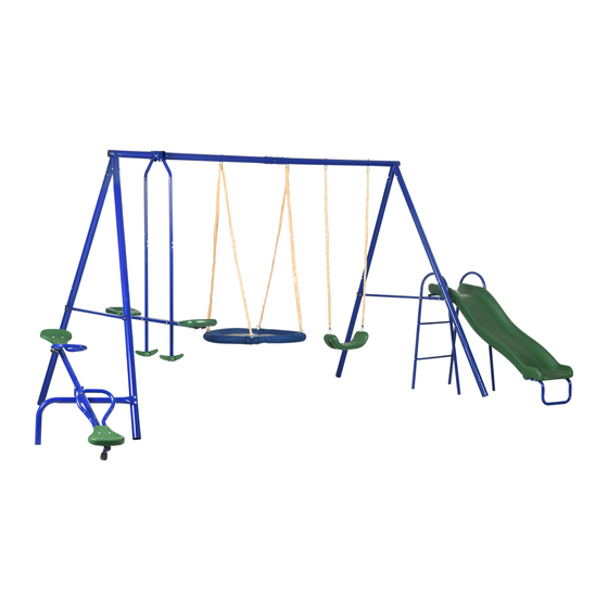
Swing set
WARNING
- This swing set is for domestic use only.
- This swing set is for ages 3-8 years. Maximum load is 40kg(88lbs)/seat.
- This swing set is for outdoor use only.
- Children of all ages must be supervised by an adult at all times when using this swing set.
- It is recommended for two adults to assemble this product.
- IMPORTANT, RETAIN FOR FUTURE REFERENCE: READ CAREFULLY
180
MIN
Tools Recommended
ASSEMBLY INSTRUCTION
1
Advertisement

Related Manuals for Outsunny 344-067V00


Summary of Contents for Outsunny 344-067V00
- Page 1 IN221100227V01_US 344-067V00 Swing set WARNING - This swing set is for domestic use only. - This swing set is for ages 3-8 years. Maximum load is 40kg(88lbs)/seat. - This swing set is for outdoor use only. - Children of all ages must be supervised by an adult at all times when using this swing set.
- Page 2 Assembled dimensions are 156*112*72 inches(396*285*183cm). Needs 2 adults to assemble, the estimated assembly time is 3 hours. Allow 6 - 12 ft of clearance around the perimeter of the swing set area when fully assembled. WARNING! Please read this entire instruction and assembly manual completely before proceeding. You must follow all safety instructions while using this equipment.
- Page 3 Children should not walk close to, in front of, behind, or between moving items. DO NOT CLIMB on the Equipment when the Equipment is wet. DO NOT attached items to the equipment that are not specifically designed for use with the equipment, such as, but not limited to, Jump Ropes, Clothesline, pet leashes, cables, and chain as they may cause a strangulation hazard.
- Page 4 ① ④ ③ ⑤ ⑥ ⑦ ⑧ ⑨ ⑩ With holes...
- Page 5 M8*65 M8*58 M6*58 M6*47 M8*42 M8*83 M6*42 M6*38 M6*35 M6*52 M6*113 M8*62 M8*56 M8*86 M6*62 M8*93...
- Page 6 M6*38 M4*12 M6*73 Note: Some parts may be supplied pre-assembled. Assembly Instructions Prior to assembling this swing set, remove all parts from the carton and check to ensure that all parts listed in the Parts List and Hardware List (on pages 4-6) are present. If you’re missing any of the parts, please call our National Service Centre to have replacement parts sent out prior to beginning assembly.
- Page 7 Step 2: Frame assembly (continued) Insert 3 into 1 and 4, secure using M8x58 mm Bolts (F2).
- Page 8 Step 3: Frame assembly (continued) Insert 5 and 31 into 3, Secure using M6x58mm Bolts (F3).as Picture 1 shown. Connect to 6 and 18. Secure using M6x62mm Bolts (Z8).as Picture 2 shown.
- Page 9 Step 4 : Glider assembly (continued) Attach the 7 to 1 and secure using M6x47mm Bolt (G1). Insert 8 into 7 and secure using G8 and M8x42mm Bolts (G2). Step 5 : Glider assembly (continued) Insert 9 into 8 Secure using M6x35mm Bolts (G10). Note: Ensure nuts face inwards (see diagram).
- Page 10 Step 6 : Glider assembly (continued) Attach 10 to 9 on either side through G9, ensuring spacers are facing the glider leg pole. Secure using M8x83mm Bolts (G4). Attach 12 to 10,Secure using M6x38mm Bolts (G6). Ensure the nut is facing down and the bolt is not protruding out, it should sit in the hole or flush to the hole.
- Page 11 Step 7: Swing seat assembly(continued) Connect J1 to 4,Secure using Nut and washer(J6), as shown in Diagram A. Connect J1 to 11,Secure using Nut and washer(J6), as shown in Diagram B. DIAGRAM A DIAGRAM B...
- Page 12 Step 8: Nest Swing assembly (continued) Connect R1 to 1 and 4,Secure using Nut and washer(J6), as the below shown. NOTE: 1.Do not over-tighten the nuts and bolts at every step. 2.Do not snap in the cover of plastic cap until you have finished the assembly of each step and went back to tighten all of the nuts and bolts.
- Page 13 Step 9: Nest Swing assembly (continued) Insert the 29 into the 28. Join the metal tubes together and then fasten them by using the bolt at the end of the R1 and J6. (See Picture 1) Repeat this for the other side, and then the nest swing becomes two semicircles. (See Picture 2) Lay the two semicircles on the ground, join the two part tubes together, and...
- Page 14 Step 10: Slide assembly(continued) Insert 21 into the base of Y2,Secure using M6x62mm Bolts (Z8). Attach 20 to Y2. Note: Make sure that the bolt holes face up. Z8 M6x62mm(x4) NOTE 1. Do not over-tighten the nuts and bolts at every step. 2.
- Page 15 Step 11: Slide assembly(continued) Attach 22 to 15 and 17, Secure using M6x35mm Bolts (G10), Attach 19 to 15 and 17, Align holes and hold in position NOTE 1. Do not over-tighten the nuts and bolts at every step. 2. Do not snap in the cover of plastic cap until you have finished the assembly of each step and went back to tighten all of the nuts and bolts.
- Page 16 Step 12: Slide assembly Attach 20 to 15 and 17, Secure using M6x52mm Bolts (Z1). Attach 19 to Y2, Secure using M6x113mm Bolts (Z2). NOTE 1. Do not over-tighten the nuts and bolts at every step. 2. Do not snap in the cover of plastic cap until you have finished the assembly of each step and went back to tighten all of the nuts and bolts.
- Page 17 Step 13: Slide assembly Fit Y1 in between 15 and 18,Secure using M8x86mm Bolts (Z7)
- Page 18 Step 14: See saw assembly Attach 27 to 31,Align the holes and Secure using M8x62mm Bolts (Z5) Step 15: See saw assembly Attach 23 to 27,Secure using M8x56mm Bolts (Z6)
- Page 19 Step 16: See saw assembly Attach 24 to 25 and 26,Secure using M4x12mm Bolts (Z11). Repeat for the other side. Step 17: See saw assembly Attach 24,25,26 to 23,Secure using M8x93mm Bolts (Z9). Repeat for the other side.
- Page 20 Step 18: See saw assembly Attach 16 to 25.26, Secure using M6x38mm Bolts (Z10). Repeat for the other side. NOTE 1. Do not over-tighten the nuts and bolts at every step. 2. Do not snap in the cover of plastic cap until you have finished the assembly of each step and went back to tighten all of the nuts and bolts.
- Page 21 Step 19: Ground pegs assembly Warning: For safety reasons this swing set MUST be anchored into the ground. To carry out this procedure you must hammer the included Ground Pegss into the ground at the angle shown in the picture above. The Ground Pegss must pull into hard earth and hold firmly.
Need help?
Do you have a question about the 344-067V00 and is the answer not in the manual?
Questions and answers