Table of Contents
Advertisement
Quick Links
G-Force
INSTRUCTION FOR INSTALLATION, OPERATION, AND MAINTENANCE
DANGER
WITH TILLER
TASK FORCE TIPS LLC
MADE IN USA · tft.com
©Copyright Task Force Tips LLC 2023
Understand manual before use. Operation of this device without understanding the manual and
receiving proper training is a misuse of this equipment. Obtain safety information at tft.com/
serial-number.
This equipment is intended for use by trained and qualified emergency services personnel for
firefighting. All personnel using this equipment shall have completed a course of education
approved by the Authority Having Jurisdiction (AHJ).
This instruction manual is intended to familiarize firefighters and maintenance personnel with the
operation, servicing, and safety procedures associated with this product. This manual should be
kept available to all operating and maintenance personnel.
FLEX
(see section 3.2)
for Flow/Pressure Operations Envelope
FLEX™ MONITOR
SERIES
FLEX RC
3701 Innovation Way, Valparaiso, IN 46383-9327 USA
800-348-2686 · 219-462-6161 · Fax 219-464-7155
1
FLEX
WITH CRANK
LIY-220 August 21, 2023 Rev00
Advertisement
Table of Contents

Related Manuals for TFT FLEX Series


Summary of Contents for TFT FLEX Series
- Page 1 Understand manual before use. Operation of this device without understanding the manual and DANGER receiving proper training is a misuse of this equipment. Obtain safety information at tft.com/ serial-number. This equipment is intended for use by trained and qualified emergency services personnel for firefighting.
- Page 2 DANGER PERSONAL RESPONSIBILITY CODE The member companies of FEMSA that provide emergency response equipment and services want responders to know and understand the following: Firefighting and Emergency Response are inherently dangerous activities requiring proper training in their hazards and the use of extreme caution at all times. 2.
-
Page 3: Table Of Contents
TABLE OF CONTENTS 1.0 MEANING OF SAFETY SIGNAL WORDS 2.0 SAFETY 3.0 GENERAL INFORMATION 3.1 MECHANICAL SPECIFICATIONS 3.2 OPERATING ENVELOPE 3.3 USE WITH SALT WATER 3.4 VARIOUS MODELS AND TERMS 3.5 INLETS AND OUTLETS 3.5.1 OUTLET ADAPTER 3.6 OVERALL DIMENSIONS 4.0 INSTALLATION 4.1 ELECTRICAL INSTALLATION 4.2 STRUCTURAL REQUIREMENTS... -
Page 4: Meaning Of Safety Signal Words
MEANING OF SAFETY SIGNAL WORDS A safety related message is identified by a safety alert symbol and a signal word to indicate the level of risk involved with a particular hazard. Per ANSI Z535.6, the definitions of the four signal words are as follows: DANGER indicates a hazardous situation which, if not avoided, will result in death or serious injury. -
Page 5: General Information
GENERAL INFORMATION FLEX is a mounted master stream monitor/ water cannon with flow ranges from 1250 GPM (4750 LPM) to 2000 GPM (7600 LPM). The unique design minimizes curves in the waterway, lowering friction loss, resulting in a higher-quality, further reaching water stream. Paired with the FLEX Ops app, the monitor is customizable and simple to install and program. -
Page 6: Operating Envelope
OPERATING ENVELOPE Damage or injury could result from operating the monitor beyond the safe operating envelope. Do WARNING not operate the monitor outside the envelope in the following graph(s). 3.5” FLEX Monitor Operating Envelope Figure 3.2A 2.5” FLEX Monitor Operating Envelope Flow (lpm) 1000 2000... -
Page 7: Use With Salt Water
USE WITH SALT WATER Use with salt water is permissible provided the equipment is thoroughly cleaned with fresh water after each use. The service life of the equipment may be shortened due to the effects of corrosion, and is not covered under warranty. VARIOUS MODELS AND TERMS rm model has a smaller swing radius and has horizontal travel stops factory installed at 90°... -
Page 8: Inlets And Outlets
MANUAL OVERRIDE KNOB FOR ELEVATION ELEVATION GEAR MOTOR MANUAL OVERRIDE KNOB FOR HORIZONTAL ROTATION HORIZONTAL ROTATION GEAR MOTOR Figure 3.4C RC Model INLETS AND OUTLETS There is a wide variety of inlet and outlet options for the FLEX monitor. The overall height and weight of the monitor may differ slightly based on the inlet and outlet configuration. -
Page 9: Overall Dimensions
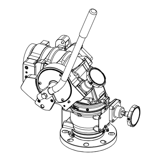
OVERALL DIMENSIONS 90° 4.31" [109 mm] 45° 10.42" 14.86" [265 mm] [377 mm] 11.94" 6.11" [303 mm] [155 mm] 8.45" [215 mm] 10.45" 7.93" SWING [265 mm] [201 mm] 18.38" [467 mm] Figure 3.6A Manual Model with Crank (Shown with 4” ANSI 150 inlet, see finished good drawing on the website for specific model dimensions) 120°... - Page 10 120° 4.59" [117 mm] 13.83" [351 mm] 9.24" [235 mm] 15.70" 45° [399 mm] 11.94" 10.137" [303 mm] [257 mm] SWING 10.45" 6.85" [265 mm] [174 mm] 17.30" [439 mm] Figure 3.6C Manual Model with Tiller (Shown with 4” ANSI 150 inlet, see finished good drawing on the website for specific model dimensions) ©Copyright Task Force Tips LLC 2023 LIY-220 August 21, 2023 Rev00...
-
Page 11: Installation
INSTALLATION ELECTRICAL INSTALLATION See Remote Control (RC) Monitor Electrical Controls Supplemental Instructions LIY-550. STRUCTURAL REQUIREMENTS Reaction forces generated by master stream flows are capable of causing injury and property WARNING damage if not properly supported. Monitors should be securely installed by qualified individuals. •... - Page 12 STEP 1 MONITOR BASE CLAMP Y4435 WASHER VW360x200-04 SOCKET HEAD SCREW 10-32 X 1-1/4 LONG Apply Loctite 242 (blue) to threads on both VT10-32SH1.2 CYLINDER NUT Cylinder Nuts. Y4437 Figure 4.3A STEP 2 TOP SIDE OF CLAMP CYLINDER NUT HEAD GROOVE Align grooves in heads of Cylinder Nuts with top sides of Clamps.
- Page 13 STEP 4 Screw monitor onto Extend-A-Gun until monitor base bottoms out against Extend-A-Gun outlet. Threaded joint seals with an O-ring and will leak if MONITOR INLET MISALIGNED "STRAIGHT monitor base bottoms out on Clamp assembly AHEAD REFERENCE MARK" instead of Extend-A-Gun outlet. Do not use pipe dope or Loctite on threads.
-
Page 14: Cable Routing For Extend-A-Gun
CABLE ROUTING FOR EXTEND-A-GUN When using a FLEX monitor on an Extend-A-GUN RC, route the cable as shown in the image below. Use the wire clamp provided on the Extend-A-Gun RC to secure the wire to the Extend-A-Gun gearbox. NOTE: CORRECT NOTE: WIRE WRAP... -
Page 15: Horizontal Rotation Travel Stops
HORIZONTAL ROTATION TRAVEL STOPS The range of horizontal rotation travel for the manual FLEX monitor is continuous 360 degrees. The motorized version is limited to 450 degrees total horizontal rotation travel, or 225 degrees from either side of a straight ahead position. Horizontal rotation travel stops may be installed at any position on the monitor to limit travel. -
Page 16: Elevation Travel Stops
ELEVATION TRAVEL STOPS The range of elevation travel for the FLEX Monitor is 30 degrees past vertical to 45 degrees below horizontal. The elevation range may be limited by installing the supplied stop bolts at the locations as shown. The figures include installation notes. 90°... -
Page 17: Nozzle Installation
NOZZLE INSTALLATION The nozzle is simply screwed onto the monitor’s exit threads. If the nozzle is installed on a FLEX RC (with electric motors) assure that the nozzle’s actuator does not make contact with the horizontal drive chain and motor housings when the monitor is in it’s lowest elevation position. -
Page 18: Operating Instructions
OPERATING INSTRUCTIONS See Remote Control (RC) Monitor Electrical Controls Supplemental Instructions LIY-550 for operation of the FLEX RC Monitors. HANDWHEEL HORIZONTAL ROTATIONAL CONTROL A handwheel controls the monitor’s horizontal rotation direction. Counterclockwise rotation of the handwheel moves the nozzle to the left and clockwise rotation to the right. -
Page 19: Flow Characteristics
FLOW CHARACTERISTICS YST-4NN STACKED TIPS FLOW AND REACH Integral Stream 2-3/4" 2-1/2" 2-1/4" 2" Protective Cap Straightener Remove cap and install smaller tips if desired. Such as Model #MST-4NJ (1-3/8", 1-1/2", 1-3/4", 2") Figure 6.1A Stacked Tip Model YST-4NN NOZZLE INLET PRESSURE NOZZLE 50 PSI 60 PSI... - Page 20 2 INCH TIP HORIZONTAL DISTANCE (M) 20.0 40.0 60.0 80.0 60 PSI 80 PSI 100 PSI 50 PSI 40.0 80.0 120.0 160.0 200.0 240.0 280.0 HORIZONTAL DISTANCE (FEET) 2.25 INCH TIP HORIZONTAL DISTANCE (M) 20.0 40.0 60.0 80.0 60 PSI 80 PSI 100 PSI 50 PSI...
-
Page 21: Mst-4Nj Stacked Tips Flow And Reach
MST-4NJ STACKED TIPS FLOW AND REACH 2" 1-3/4" 1-1/2" 1-3/8" 2.5” Coupling Figure 6.2A Stacked Tip Model MST-4NJ NOZZLE INLET PRESSURE NOZZLE 40 PSI 60 PSI 80 PSI 100 PSI DIAMETER FLOW REACTION FLOW REACTION FLOW REACTION FLOW REACTION (GPM) (LBS) (GPM) (LBS) - Page 22 1.375 INCH TIP HORIZONTAL DISTANCE (M) 80.0 60 PSI 80 PSI 100 PSI 40 PSI 40.0 80.0 120.0 160.0 200.0 240.0 280.0 HORIZONTAL DISTANCE (FEET) 1.50 INCH TIP HORIZONTAL DISTANCE (M) 80.0 60 PSI 80 PSI 100 PSI 40 PSI 40.0 80.0 120.0...
-
Page 23: Effects Of Elevation And Wind On Stream Reach
EFFECTS OF ELEVATION AND WIND ON STREAM REACH This graph shows approximately how differences in elevation angle can affect stream reach. Critical applications should be tested in actual conditions to verify adequate reach. HORIZONTAL DISTANCE (METERS) 75 DEGREES 2.0 INCH TIP, 100 PSI, 1190 GPM 60 DEGREES 45 DEGREES 30 DEGREES... -
Page 24: Automatic Masterstream Nozzles
AUTOMATIC MASTERSTREAM NOZZLES Automatic nozzles maintain a constant pressure by adjusting their orifice to match the available flow. Consult the nozzle manufacturer for maximum flow and pressure range. In all cases, do not exceed the maximum rating of the FLEX Operating Envelope. FRICTION LOSS The discharge size of the monitor determines maximum flow. -
Page 25: Stream Straighteners
Turbulence though the FLEX Monitor is very low, but stream quality and reach can be improved with the use of the integral stream straightener on the TFT stacked tip nozzle. Stream straighteners will add some friction loss as indicated below. -
Page 26: Warranty
TFT’s obligation under this warranty is specifically limited to replacing or repairing the equipment (or its parts) which are shown by TFT’s examination to be in a defective condition attributable to TFT. To qualify for this limited warranty, the claimant must return the equipment to TFT, at 3701 Innovation Way, Valparaiso, Indiana 46383-9327 USA, within a reasonable time after discovery of the defect. -
Page 27: Maintenance
MAINTENANCE TFT products are designed and manufactured to be damage resistant and require minimal maintenance. However, as the primary firefighting tool upon which your life depends, it should be treated accordingly. To help prevent mechanical damage, do not drop or throw equipment. -
Page 28: Repair
Repair parts and service procedures are available for those wishing to perform their own repairs. Task Force Tips assumes no liability for damage to equipment or injury to personnel that is a result of user service. Contact the factory or visit the web site at tft.com for parts lists, exploded views, test procedures and troubleshooting guides.
Need help?
Do you have a question about the FLEX Series and is the answer not in the manual?
Questions and answers