Table of Contents
Advertisement
Quick Links
Advertisement
Table of Contents

Subscribe to Our Youtube Channel
Related Manuals for Bromic Heating INSTANTANEOUS Series

Summary of Contents for Bromic Heating INSTANTANEOUS Series
- Page 1 INSTANTANEOUS ELECTRIC HOT WATER 3 - PHASE MODEL V5 - 03/2023...
-
Page 2: Table Of Contents
CONTENTS 1. PREFIX 2. IMPORTANT NOTES & WARNINGS 3. PRODUCT OVERVIEW 4. INSTALLATION 5. OPERATION 6. USER CARE 7. MAINTENANCE 8. TROUBLESHOOTING 9. WIRING DIAGRAM 10. WARRANTY bromichotwater.com 1300 276 642... -
Page 3: Prefix
1. PREFIX This manual contains important information about the installation, operating and maintenance of the Bromic Instantaneous Electric Hot Water Heaters. Please pay close attention to the important safety information shown throughout this instruction manual. Any safety information will be accompanied by the following safety alert symbols: DANGER, WARNING, IMPORTANT... -
Page 4: Important Notes & Warnings
2. IMPORTANT NOTES AND WARNINGS IMPORTANT • Read all instructions before installing or using this appliance. • Installation must be performed by a qualified technician in compliance with AS/NZS 3500.4 Plumbing and drainage: Heated water service and Clause G12 of the NZ Building Code as well as all other current national and local regulations. -
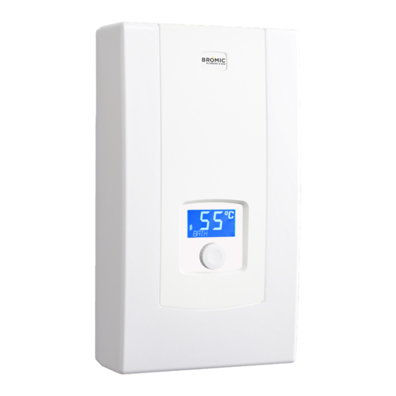
Page 5: Product Overview
3. PRODUCT OVERVIEW The Bromic Instantaneous series is a closed instantaneous water heater. 18 kW 21 kW 24 kW 27 kW Part number 2850318 2850321 2850324 2850327 Type Instantaneous Instantaneous Instantaneous Instantaneous Voltage, V 415V 415V 415V 415V Rated Power, kW Rated Current, A (3 phase) 25.1... -
Page 6: Installation
4. INSTALLATION WARNING • Installation must be performed by a qualified technician in compliance with AS/NZS 3500.4 Plumbing and drainage: Heated water service and Clause G12 of the NZ Building Code as well as all other current national and local regulations. •... - Page 7 • Reheating pre-heated water allows the heater to interact with other devices. The inlet water temperature can be up to 40°C. This solution allows the heater to interact with another heat source and preheat water with the use of, for example, a solid fuel boiler in cooperation with a hot water tank.
- Page 8 IMPORTANT Appliance installation clearance. bromichotwater.com 1300 276 642...
- Page 9 4.2 ELECTRICAL CONNECTION WARNING • Ensure the electrical wiring installation conforms with the requirement stipulated in AS/NZ3000. • The appliance must be permanently connected to fixed wiring. • The appliance must be earthed. • Electric installation MUST be equipped with residual current protective devices and other devices that ensure disconnection of power (all poles are disconnected by at least 3mm separation) •...
-
Page 10: Operation
Make sure that the safety cutoff switch, as indicated below (WTC3) is at working position. The knob should be pushed in. Connect the power supply cables to the heater. Make sure that the safety cut-out reset button is pushed in. III. - Page 11 5.2 HF MODEL OPERATION • The heater switches on automatically when the flow rate is over 2.5L/min. • The temperature control system adjusts the power according to the water flow rate, required temperature and supply water temperature. • The LCD backlight and icon indicates that the heater is actively heating water.
- Page 12 5.2.2 CONFIGURATION AND PARAMETER VIEW Adjust the temperature value to the minimum in manual mode. Push and hold the knob for about 5 seconds until the display shows ‘>SET TEMP’. a. Push the knob again, the display will flash at 30°C. b.
- Page 13 5.2.2 CONFIGURATION AND PARAMETER VIEW (CONTINUED) Notes: • After setting ’>TEMP LIMIT’, any pre-set above the limit will be adjusted to the new value. • If you try to adjust the set temperature above the limit, a icon will show. •...
-
Page 14: User Care
6. USER CARE IMPORTANT! • Check for damage to the appliance regularly. If damage to the appliance is suspected, discontinue use immediately and contact the supplier or qualified person to repair. • Do not use any abrasive or corrosive cleaning agents. •... - Page 15 7.2 FILTER CLEANING IMPORTANT! • Failure to install the filter on the water supply pipe may cause damage to the heater. Isolate the power from the appliance and shut-off the cold water supply. Remove the front cover. III. Undo the inlet fitting on the cold water side. Remove the filter from the inlet fitting.
-
Page 16: Troubleshooting
8. TROUBLESHOOTING IMPORTANT! • Repairs on the unit must be carried out by qualified and licensed technicians only. Contact the manufacturer or an approved service agent for any repairs needed. • Refer to the error codes shown for each model. •... -
Page 17: Wiring Diagram
9. WIRING DIAGRAM ON BOX E1 = Heating box Twej = Inlet temperature sensor F1 = Safety cut-out & Supply/Earth connec- Twyj = Outlet temperature sensor tion NA = Control appliance by master device XG = Terminal for heating box BLOK = Control a slave appliance BV = Flow sensor XP = Disconnection Device (external and not... - Page 18 SYDNEY HEAD OFFICE 10 Phiney Place, Ingleburn NSW 2565 Australia T: AU 1300 276 642 F: (+61) 1300 735 115 E: plumbing@bromic.com BROMICHOTWATER.COM...
Need help?
Do you have a question about the INSTANTANEOUS Series and is the answer not in the manual?
Questions and answers