
Related Manuals for DAEWOO ELECTRONICS KOC-1BOK6S


Summary of Contents for DAEWOO ELECTRONICS KOC-1BOK6S
- Page 1 All manuals and user guides at all-guides.com S/M No. : C1B0K6S001 Service Manual Microwave Oven Model: KOC-1B0K6S DAEWOO ELECTRONICS CO., LTD. http://svc.dwe.co.kr Feb. 2001...
-
Page 2: Table Of Contents
All manuals and user guides at all-guides.com PRECAUTIONS TO BE OBSERVED BEFORE AND DURING SERVICING TO AVOID POSSIBLE EXPOSURE TO EXCESSIVE MICROWAVE ENERGY (a) Do not operate or allow the oven to be operated with the door open. (b) Make the following safety checks on all ovens to be serviced before activating the magnetron or other microwave source, and make repairs if necessary: (1) Interlock operation, (2) Proper door closing, (3) Seal and sealing surfaces (arcing, wear, and other damage), (4) Damage to or loosening of hinges and latches (5) Evidence of dropping or abuse. -
Page 3: Safety And Precautions
All manuals and user guides at all-guides.com 1. SAFETY AND PRECAUTIONS 1. FOR SAFE OPERATION Damage that allows the microwave energy (that cooks or heats the food) to escape will result in poor cooking and may cause serious bodily injury to the operator. IF ANY OF THE FOLLOWING CONDITIONS EXIST, OPERATOR MUST NOT USE THE APPLIANCE. -
Page 4: Specifications
All manuals and user guides at all-guides.com 2. SPECIFICATIONS MODEL KOC-1B0K6S POWER SUPPLY 230V~50HZ, SINGLE PHASE WITH EARTHING MICROWAVE 1500W POWER GRILL 1600W CONSUMPTION CONVECTION 2300W COMBINATION 2300W MICROWAVE ENERGY OUTPUT 1000W(IEC705) MICROWAVE FREQUENCY 2450MHz OUTSIDE DIMENSIONS (W X H X D) 560X344X542mm (22.0X13.0X21.3 in.) CAVITY DIMENSIONS (W X H X D) 368.5X246X376.5mm (14.5X9.7X14.8 in.) -
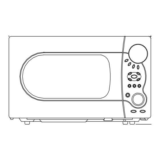
Page 5: Feature Diagram
All manuals and user guides at all-guides.com 2. FEATURE DIAGRAM 11.DOOR HOOK When the door is closed, it will automatically lock shut. If door is opened while oven is operating, the magnetron will immediately stop operating. 12.DOOR VIEWING SCREEN Allows viewing of food. The screen is designed so that light can pass through, but not the microwave. 13.METAL RACK 14.TOP HEATER Turns on when convection, grill and combi cooking is selected. -
Page 6: Installation
All manuals and user guides at all-guides.com 4. INSTALLATION 1. Steady, flat location This microwave oven should be set on a steady, flat surface. This microwave oven is designed for counter top use only. 2. Leave space behind and side All air vents should be kept a clearance. -
Page 7: Control Panel
All manuals and user guides at all-guides.com 5. CONTROL PANEL DISPLAY WINDOW 1. MICROWAVE - indicator, showing microwaving in progress. 2. DEFROST- indicator, showing defrosting in progress. 3. GRILL(upper grill heater) - indicator, showing griling in progress. 4. GRILL(lower grill heater) - indicator, showing griling in progress. -
Page 8: Disassembly And Assembly
All manuals and user guides at all-guides.com 6. DISASSEMBLY AND ASSEMBLY - Cautions to be observed when trouble shooting. Unlike many other appliances, the microwave oven is high-voltage, high-current equipment. It is completely safe during normal operation. However, carelessness in servicing the oven can result in an electric shock or possible danger from a short circuit. - Page 9 All manuals and user guides at all-guides.com 1. To remove cabinet 1) Remove four screws on cabinet back. 2) Push the cabinet backward. 2. To remove guide wind assembly 1) Remove two screws which secure the stopper hinge top. 2) Remove the door assembly from top plate of cavity. 3) Reverse the above for assemby.
- Page 10 All manuals and user guides at all-guides.com (1) Remove the gasket door from door plate. (2) Remove screws from door plate. (3) Remove the door frame from door plate. (4) Remove the stopper hinge top from door plate. (5) Remove the spring and the hook. (6) Remove the handle door and barrier screen outer from door frame.
- Page 11 All manuals and user guides at all-guides.com 5. To remove control panel parts. REF NO. PART CODE PART NAME DESCRIPTION Q’TY REMARK 3511605000 DECORATOR C-PANEL ABS XR-401 H-2938 3511605100 DECORATOR RING ABS SG-175 SG-0760D 3515501700 WINDOW DISPLAY PMMA 3516724100 CONTROL PANEL ABS XR-401 H-2938 3516908300 BUTTON FUNCTION-A...
- Page 12 All manuals and user guides at all-guides.com 6. To remove high voltage capacitor. 1) Remove a screw which secure the grounding ring terminal of the H.V. diode and the capacitor holder. 2) Remove the H.V. diode from the capacitor holder. 3) Reverse the above steps for reassembly.
- Page 13 All manuals and user guides at all-guides.com 8. To remove wind guide assembly. 1) Remove a screw for earthing. 2) Remove the noise filter from the wind guide. 3) Remove a screw which secure the wind guide assembly. 4) Draw forward the wind guide assembly. 5) Pull the fan from the motor shaft.
- Page 14 All manuals and user guides at all-guides.com 10. To remove Lamp assembly parts. REF NO. PART CODE PART NAME DESCRIPTION Q’Y REMARK 7112401011 SCREW TAPPING T1 TRS 4X10 MFZN 3512520500 GUIDE AIR OUTLET SA1D T0.6 3513302800 INSULATOR HEATER*T SBHG T0.5 7112401011 SCREW TAPPING T1 TRS 4X10 MFZN...
- Page 15 All manuals and user guides at all-guides.com 11. To remove Top heater assembly parts. REF NO. PART CODE PART NAME DESCRIPTIOT Q’TY REMARK 7112401011 SCREW TAPPING T1 TRS 4X10 MFZN 3512520500 GUIDE AIR OUTLET SA1D T0.5 3513302800 INSULATOR HEATER*T SBHG T0.6 7112401011 SCREW TAPPING T1 TRS 4X10 MFZN...
- Page 16 All manuals and user guides at all-guides.com 12. To remove Rear heater assembly parts. REF NO. PART CODE PART NAME DESCRIPTION Q’TY REMARK 7112401011 SCREW TAPPING T1 TRS 4X10 MFZN 3511407300 COVER MOTOR*B SA1D-80 T0.5 7112401011 SCREW TAPPING T1 TRS 4X10 MFZN 3511407400 COVER*B SBHG T0.6...
- Page 17 All manuals and user guides at all-guides.com 13. To remove Motor synchro. And Under heater assembly parts. REF NO. PART CODE PART NAME DESCRIPTION Q’TY REMARK 7112401011 SCREW TAPPING T1 TRS 4X10 MFZN 3511407500 COVER HEATER *U STS430 T0.5 3515304000 SUPPORTER HEATER *U STS430 T0.5 3512802000...
-
Page 18: Interlock Mechanism And Adjustment
All manuals and user guides at all-guides.com 7. INTERLOCK MECHANISM AND ADJUSTMENT The door lock mechanism is a device which has been specially designed to completely eliminate microwave radiation when the door is opened during operation, and thus to perfectly prevent the danger resulting from the leakage of microwave. (1) Primary interlock switch When the door is closed, the hook locks the oven door. -
Page 19: Trouble Shooting Guide
All manuals and user guides at all-guides.com 8. TROUBLE SHOOTING GUIDE Following the procedure below to check if the oven is defective or not. 1) Check grounding before trouble checking. 2) Be careful of the high voltage circuit. 3) Discharge the high voltage capacitor. 4) When checking the continuity of the switches, fuse or high voltage tranformer, disconnect one load wire from these parts and check continuity with the AC plug removed. - Page 20 All manuals and user guides at all-guides.com CONDITION CHECK RESULT CAUSE REMEDY Defective Outlet has Check continuity of Replace continuity magnetron. proper magnetron voltage fuse does not blow? Defective line Check continuity of noise filter Replace continuity filter board board Open power Check continuity of Replace...
- Page 21 All manuals and user guides at all-guides.com TROUBLE 3) No microwave oscillation even though fan motor rotates. CONDITION CHECK RESULT CAUSE REMEDY Check continuity of Replace Defective continuity high voltage fuse microwave high voltage oscillation fuse No microwave oscillation Continuity Check continuity of Defective high voltage capacitor terminals...
- Page 22 All manuals and user guides at all-guides.com (TROUBLE 4) Grill heater (upper heater) is not heated; food will not become hot. CONDITION CHECK RESULT CAUSE REMEDY Malfunction of Adjust or Check continuity of Grill heater is primary Interlock replace continuity primary interlock switch not heated.
- Page 23 All manuals and user guides at all-guides.com (TROUBLE 6) Lower heater is not heated; food will not become hot. CONDITION CHECK RESULT CAUSE REMEDY Malfunction of Adjust or Check continuity of Bottom primary Interlock Replace continuity Primary interlock switch heater is not switch heated.
- Page 24 All manuals and user guides at all-guides.com (TROUBLE 8) When “ERROR 2”, “ERROR 3” come on display. CAUSE REMEDY CONDITION CHECK RESULT “ERROR 2 & 0Ω or infinite Replace Replace Check continuity of thermistor ERROR 3” (resistance of thermistor) come on display Approx 200k~300kΩ...
-
Page 25: Mesurement And Test
All manuals and user guides at all-guides.com 9. MEASUREMENT AND TEST 1. MEASUREMENT OF THE MICROWAVE POWER OUTPUT Microwave output power can be checked by indirectly measuring the temperature rise of a certain amount of water exposed to the microwave as directed below. PROCEDURE 1. -
Page 26: Microwave Radiation Test
All manuals and user guides at all-guides.com 2. MICROWAVE RADIATION TEST WARNING 1. Make sure to check the microwave leakage before and after repair of adjustment. 2. Always start measuring of an unknown field to assure safety for operating personnel from microwave energy. 3. -
Page 27: Component Test Procedure
All manuals and user guides at all-guides.com 3. COMPONENT TEST PROCEDURE • High voltage is present at the high voltage terminal of the high voltage transformer during any cooking cycle. • It is neither necessary nor advisable to attempt measurement of the high voltage. •... -
Page 28: Component Action
All manuals and user guides at all-guides.com 4. COMPONENT ACTION MAGNE- UPPER LOWER REAR CONVEC- COOKING MODE TRON ELEMENT ELEMENT ELEMENT TION FAN GRILL-1 GRILL-2 GRILL-3 COMBI-1 COMBI-2 MANUAL COMBI-3 MODE COMBI-4 COMBI-5 CONVECTION100~130 CONVECTION140~150 CONVECTION160~250 CAKE/BREAD TOUCH CRUSTY ROAST BEEF ROAST CHICKEN ROAST PORK AUTO... -
Page 29: Wiring Diagram
All manuals and user guides at all-guides.com 10. WIRING DIAGRAM... -
Page 30: Exploded View And Parts List
All manuals and user guides at all-guides.com 11. EXPLODED VIEW AND PARTS LIST 1. DOOR ASSEMBLY Refer to 6. Disassembly and assembly. 2. CONTROL PANEL ASSEMBLY Refer to 6. Disassembly and assembly. 3. TOTAL ASSEMBLY... - Page 31 All manuals and user guides at all-guides.com PART CODE PART NAME DESCRIPTION Q'TY 3511714000 DOOR AS KOC-1B0K0S 3516724970 CONTROL PANEL AS KOC-1B0K6S 3515202800 STOPPER HINGE *U AS KOR-121MOA 7172400811 SCREW TAPTITE TT3 TRS 4X8 MFZN 3510313510 BASE SBHG T0.8 7112401011 SCREW TAPPING T1 TRS 4X10 MFZN 4413A12030...
- Page 32 All manuals and user guides at all-guides.com PART CODE PART NAME DESCRIPTION Q'TY 3512766800 HARNESS CONVECTION-A KOC-1B0K0S 3511407700 COVER HEATER *B SA1D-80 T0.5 3513302900 INSULATOR HEATER *B SBHG-1 T0.5 7113400814 SCREW TAPPING T1 BIN 4X8 MFNI 3963514300 MOTOR SHADED POLE 230V 50HZ MW10CA-T02 3511800800 PP GF20...
- Page 33 All manuals and user guides at all-guides.com PART CODE PART NAME DESCRIPTION Q'TY 7112401011 SCREW TAPPING T1 TRS 4X10 MFZN 3512767000 HARNESS HEATER KOC-1B0K0S 3517207300 TRAY RACK AS KOC-1B0K0S 120MM 3517207310 TRAY RACK AS KOC-1B0K0S 30MM 3517205200 TRAY METAL SPP T0.6 3512521000 GUIDE ROLLER AS KOC-1B0K0S...
-
Page 34: Printed Circuit Board
All manuals and user guides at all-guides.com 12. PRINTED CIRCUIT BOARD CIRCUIT CHECK PROCEDURE 1. Low voltage transformer check The low voltage transformer is located on the P.C.B. Measuring condition: Input voltage: 230V / Frequency: 50Hz Terminal Voltage(olad) Voltage(no load) AC 17.0 V AC 19.9 V AC 1.3 V... - Page 35 All manuals and user guides at all-guides.com 3. Case of no microwave oscillation 1) When touching M/W button, oven lamp turns on and Fan motor and turn table rotate, and cook indicator in display comes on. *Cause: RELAY 1 does not operate. STATE POINT A POINT B...
- Page 36 All manuals and user guides at all-guides.com 4. Case of no heating of upper grill When touching GRILL1 & COMBI button, oven lamp turns on and Fan motor and turntable rotate, and cook indicator in display comes on. *Cause: RELAY 2 does not operate. STATE POINT A POINT B...
- Page 37 All manuals and user guides at all-guides.com 7. Case of no stopping of the count down timer When the door is opened during operation, the count down timer does not stop. POINT STATE DOOR OPEN OPEN +5V DC DOOR CLOSED CLOSE CHECK NO METHOD...
-
Page 38: Circuit Diagram
All manuals and user guides at all-guides.com 13. P.C.B. CIRCUIT DIAGRAM... - Page 39 All manuals and user guides at all-guides.com PCB ASS’Y PART LIST NAME SYMBOL SPECIFCATION PART CODE Q'TY PCB MAIN M233 95.5 X 220 3514322740 PCB SUB M234 90 X 220 3514322750 BUZZER BM-20K 3515600100 BATTERY BTR1 N-270AA 1.2V x3 3517900100 CAPACITOR CERAMIC C1,C2,C8~C13 104 50V Z AXIAL...
- Page 40 All manuals and user guides at all-guides.com NAME SYMBOL SPECIFCATION PART CODE Q'TY RESISTOR R21,R22 1/2W 200 Ohm 5% RD-2Z201JS RESISTOR 1/4W 301K OHM 1% RN-4Z3013F RESISTOR 1/4W 10K OHM 1% RN-4Z1002F RESISTOR 1/4W 120K OHM 1% RN-4Z1203F RESISTOR ARRAY 7P(6) 1/8 100K 5% RA-87X104J RESISTOR ARRAY...
- Page 41 All manuals and user guides at all-guides.com DAEWOO ELECTRONICS CO., LTD. 686, AHYEON-DONG MAPO-GU SEOUL, KOREA C.P.O. BOX 8003 SEOUL, KOREA TELEX: DWELEC K28177-8 CABLE: “DAEWOOELEC” FAX: 02) 360-8184 TEL: 02) 360-8183 http://www.dwe.daewoo.co.kr PRINTED DATE: Feb, 2001 S/M NO.:C1B0K6S001...
Need help?
Do you have a question about the KOC-1BOK6S and is the answer not in the manual?
Questions and answers