
Related Manuals for Woodward 8273-587


Summary of Contents for Woodward 8273-587
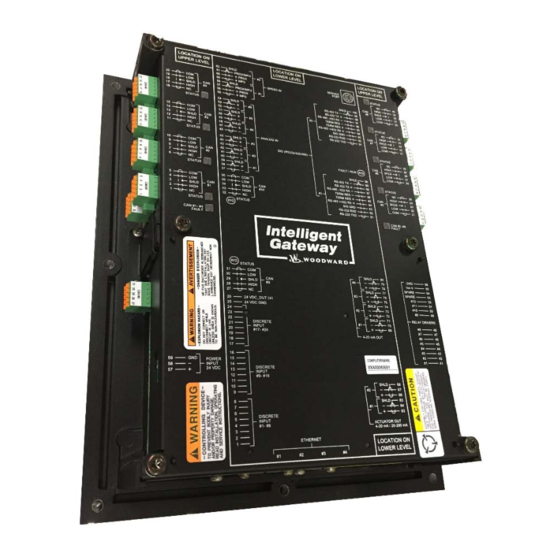
- Page 1 Product Manual 35012 (Revision New, 6/2015) Original Instructions Intelligent Gateway Control Part Numbers 8273-587 Installation and Operation Manual...
- Page 2 Revisions—Changes in this publication since the last revision are indicated by a black line alongside the text. Woodward reserves the right to update any portion of this publication at any time. Information provided by Woodward is believed to be correct and reliable. However, no responsibility is assumed by Woodward unless otherwise expressly undertaken.
-
Page 3: Table Of Contents
Product Service Options ..................74 Returning Equipment for Repair ................75 Replacement Parts ....................76 Engineering Services .................... 76 Contacting Woodward’s Support Organization ............ 76 Technical Assistance .................... 77 A. A ......... 78 PPENDIX CRONYMS AND... - Page 4 Figure 5-9. CPU Service Port (mini-DIN6F) ............56 Figure 5-10. CAN Communication Ports .............. 57 Figure 5-11. Descriptions of Main Cabinet Cabling Options ........ 63 Figure 8-1. CAN Ports #1–#4 Status and Fault Indicators ........70 Woodward...
- Page 5 Table 8-3. CAN FAULT Indicators ................ 72 Table 8-4. Gateway Unit Fault Codes ..............72 The following are trademarks of Woodward, Inc.: LINKnet MicroNet RTCnet The following are trademarks of their respective companies: DeviceNet (Open DeviceNet Vendor Association, Inc. [ODVA]) VxWorks (Wind River Systems, Inc.)
-
Page 6: Warnings And Notices
Start-up On- and off-highway Mobile Applications: Unless Woodward's control functions as the supervisory control, customer should install a system totally independent of the prime mover control system that... -
Page 7: Electrostatic Discharge Awareness
Do not touch the components or conductors on a printed circuit board with your hands or with conductive devices. To prevent damage to electronic components caused by improper handling, read and observe the precautions in Woodward manual 82715 , Guide for Handling and Protection of Electronic Controls, Printed Circuit Boards, and Modules. -
Page 8: Regulatory Compliance
60079-15. The interior of the enclosure shall not be accessible without the use of a tool. ATEX/IECEx Explosive Atmosphere locations require the enclosure be coded Ex nA or Ex e and provide a minimum ingress protection IP54 per IEC 60529. Woodward... - Page 9 The Intelligent Gateway contains a single-cell primary battery suitable for the life of the product. This battery is not to be charged and is not customer replaceable. If real-time clock functionality is interrupted, contact your Woodward representative. The control is suitable for installation in pollution degree 2 environments.
- Page 10 The switch or circuit breaker shall Emergency be clearly marked as the disconnecting device for the equipment. Disconnecting The switch or circuit breaker shall not interrupt the Protective Earth Service (PE) conductor. Woodward...
- Page 11 Installation of the Intelligent Gateway in a metal enclosure, as intended, will also prevent performance degradation. Both direct and alternating current Alternating current Direct current Caution, risk of electrical shock Caution, refer to accompanying documents Protective conductor terminal Frame or chassis terminal Woodward...
-
Page 12: Chapter 1. General Information
Once the application program has been generated and loaded into the Intelligent Gateway control, the user can view variables and tune the control with a variety of Woodward service tools. Connection to other devices, such as an HMI, is accomplished by means of serial Modbus or Ethernet ports on the control. - Page 13 Control Accessories The Intelligent Gateway digital control platform is designed to interface with several Woodward service tools and commercial software products. Available tools are listed below with a brief description of their functionality: Monitor GAP—an Ethernet connection to the control allows on-line GAP monitoring, debug, and tunable configuration.
-
Page 14: Chapter 2. Power Supply Board
Power Supply Board General Description Woodward’s Intelligent Gateway consists of three PC boards: a Power Supply board (described in this chapter), a SmartCore CPU A5200 board and an 8- channel CAN bus board (both describe in Chapter 3). The Intelligent Gateway power supply contains the power supply and twelve discrete output driver channels. - Page 15 Troubleshooting Guide Power Supply Checks The following is a troubleshooting guide for checking areas, which may present difficulties. If these checks are made prior to contacting Woodward for technical assistance, system problems can be more quickly and accurately assessed. ...
-
Page 16: Figure 2-2. Discrete Output Wiring Example
250% of the maximum rated current of the load (Discrete Output power input current plus 12 times the maximum Discrete Output channel current) shall be provided. Fuse current rating should not exceed 6.25 A (time delay fuses are recommended). Woodward... -
Page 17: Chapter 3. Cpu A5200 And Can Board
CPU A5200 and CAN Board Intelligent Gateway General Description Woodward’s Intelligent Gateway consists of three PC boards: a SmartCore CPU A5200 board, an 8-channel CAN bus board, and a Power Supply board (described in Chapter 2). The Intelligent Gateway has the following features: ... -
Page 18: Smartcore Cpu A5200 Board
Analog input and output circuits are 4–20 mA. The actuator driver outputs may be configured as either 4–20 mA or 20–220 mA. The user serial ports are configurable as RS-232, RS-422, or RS-485. Figure 3-1. SmartCore CPU A5200 Board Connectors Woodward... -
Page 19: Figure 3-2. Block Diagram -- Intelligent Gateway Smartcore Cpu A5200
All of the boards are held together and to the chassis, by bolts. The SmartCore CPU A5200 board is the size of two analog boards. Figure 3-2. Block Diagram -- Intelligent Gateway SmartCore CPU A5200 Board Woodward... -
Page 20: Can Communications Board
CAN networks from different processing units to increase reliability. One processing unit manages CAN ports #1 to #4 and the second processing unit manages CAN ports #5 to #8. Figure 3-3. Eight Channel CAN Communication Board Woodward... -
Page 21: Figure 3-4. Block Diagram - Intelligent Gateway 8-Channel Can Board
Manual 35012 Intelligent Gateway CAN communications Board Block Diagram Figure 3-4. Block Diagram – Intelligent Gateway 8-Channel CAN Board Woodward... -
Page 22: Intelligent Gateway Module Configuration
Ethernet #4 = 192.168.130.22, Subnet Mask = 255.255.255.0 Network Configuration Utility (AppManager) Woodward's AppManager software can be used to load GAP Control software, monitor diagnostic faults, and configure Network settings. The AppManager utility can be downloaded from www.woodward.com/software. A PC to Intelligent Gateway connection must be made using an Ethernet cable and Ethernet port ... -
Page 23: Figure 3-5. Smartcore Cpu A5200 Communications Ports (Sio1, Sio2)
An isolated RS-232 service port is located near one corner of the A5200 CPU module. This port is for VxWorks operating system use only and cannot be configured for application software use. The communication settings are fixed at 38.4 kBaud, 8 data bits, no parity, 1 stop-bit, and no flow control. Woodward... -
Page 24: Figure 3-6. Cpu Service Port (Mini-Din6F)
Ten CAN ports (5 pin pluggable connectors, screw down) are available for communication with Woodward Valves and other CAN devices. A maximum of 15 Woodward valves configured for operation in the 10 ms rate group may be used. Pin 1 – not used Pin 2 –... -
Page 25: Hardware Specifications
MPU/PROX(+) terminal block input is shorted to MPU/PROX (–). MPU Minimum Input Magnitude 1000 10000 100000 Frequency (Hz) Figure 3-9. MPU Minimum Input Magnitude in Vrms To convert to V peak to peak, multiply by 2.828. Woodward... -
Page 26: Figure 3-10. Mpu Maximum Input Magnitude In Vrms
Typ Impedance Phase at 14.6 Vrms Input Typ Impedance Phase at 1 Vrms Input 10000 3066 2427 2001 1718 1553 1503 1498 1470 26 25 1216 1000 1000 10000 100000 Frequency (Hz) Figure 3-11. MPU Typical Input Impedance Magnitude and Phase Woodward... - Page 27 Note: Shielded cable is required when connecting to the Analog Inputs. Loop power for the analog inputs is NOT available Only 4–20 mA inputs are supported. This is a change from the previous SmartCore module that allowed both current and voltage inputs Woodward...
- Page 28 > 16 Vdc = “ON” Input current 3 mA @ 24 Vdc Contact voltage 24 Vdc isolated output (100 mA max, internally protected) Max input voltage 28 Vdc Isolation voltage 500 Vac, all channels are isolated from the Intelligent Gateway platform Woodward...
-
Page 29: Smartcore Cpu A5200 Board Operation
(reducing speed sensing resolution) and have coupling gear backlash, resulting in less than optimum speed control. For safety purposes, it is also not recommended that the speed sensing device sense speed from a gear coupled to a generator or mechanical drive side of a system’s rotor coupling. Woodward... -
Page 30: Figure 3-12. Wiring Example-Mpu Interface To The Smartcore Board
0.5 Hz. When interfacing to open collector type proximity probes, a pull-up resistor is required between the supplied proximity probe voltage and the proximity probe input to the SmartCore CPU A5200 board. Figure 3-13. Wiring Example–Open Collector Proximity Probe to the SmartCore CPU A5200 Board Woodward... -
Page 31: Figure 3-14A. Wiring Example-4-20 Ma Input Interface To The Smartcore Cpu A5200 Board
For a 4–20 mA input signal, the SmartCore CPU A5200 board uses a 211 Ω resistor across the input. Figure 3-14a. Wiring Example–4–20 mA Input Interface to the SmartCore CPU A5200 Board Woodward... -
Page 32: Figure 3-14B. Wiring Example-4-20 Ma Input Interface Using External Loop Power
Analog Outputs The analog outputs are 4–20 mA with a full scale range of 0–25 mA. The SmartCore CPU A5200 board has four analog outputs. +15 Vdc 4‐20 mA Figure 3-15. Wiring Example–Analog Output Interface to the SmartCore CPU A5200 Board Woodward... -
Page 33: Figure 3-16. Wiring Example-Actuator Output Interface To The Smartcore Cpu A5200 Board
Figure 3-16. Wiring Example–Actuator Output Interface to the SmartCore CPU A5200 Board Configuration Notes Refer to Figure 3-16 for actuator output wiring. 4–20 mA or 20-200 mA signals are output. See the specifications section for the maximum actuator output load. Woodward... -
Page 34: Figure 3-17. Wiring Example-Discrete Input Interface To The Smartcore Cpu
100/V (where V is the supply’s rated voltage), or a 5 A fuse, whichever is less). The 24 V isolated contact power is protected by a 0.3 A poly switch that is rated for 0.1 A continuous use. This may not prevent interruption in control Woodward... -
Page 35: Figure 3-18. Serial #1-Rs-232 Pinouts
The SmartCore CPU A5200 accepts (2) user serial I/O connections. Both isolated ports are configurable for RS-232, RS-422, or RS-485. RS-232 is specified to 50 feet (15 m) while RS-485 and RS-422 are specified to 4000 feet (1219 m). Figure 3-18. Serial #1–RS-232 Pinouts Figure 3-19. Serial #1–RS-422 Pinouts Woodward... -
Page 36: Figure 3-20. Serial #1-Rs-485 Pinouts
Intelligent Gateway Manual 35012 Figure 3-20. Serial #1–RS-485 Pinouts Figure 3-21. Serial #2–RS-232 Pinouts Woodward... -
Page 37: Figure 3-22. Serial #2-Rs-422 Pinouts
Manual 35012 Intelligent Gateway Figure 3-22. Serial #2–RS-422 Pinouts Figure 3-23. Serial #2–RS-485 Pinouts Woodward... -
Page 38: Figure 3-24. Wiring Example-Rs-232 Interface To The Smartcore Cpu A5200 Board
Figure 3-25. Wiring Example–RS-422 Interface to the SmartCore CPU A5200 Board Figure 3-26. Wiring Example–RS-485 Interface to the SmartCore CPU A5200 Board Figure 3-27. Wiring Example–Alternate Multipoint Wiring (without a separate signal ground wire for the SmartCore CPU A5200 board) Woodward... - Page 39 LED remains on or blinks. If the test is successful, the LED goes off. If the fault LED on a board is illuminated after the diagnostics and initialization have been completed, the SmartCore CPU A5200 board may be faulty. Woodward...
- Page 40 Check the wiring. Look for a loose connection at the terminal blocks and disconnected or misconnected cables. Check the software configuration to ensure that the input is configured properly. After verifying all of the above, the Intelligent Gateway should be returned for service. Woodward...
- Page 41 Check the load resistance, ensure that it is less than the specification limit for the output current. Check to ensure that the load wiring is isolated. Check the wiring, look for a loose connection at the terminal blocks and disconnected or misconnected cables. Woodward...
- Page 42 Check the software configuration to ensure that the input is configured properly. Check that the cable is shielded and the shield is properly grounded per the shields and grounding section in Chapter 5. After verifying all of the above, the Intelligent Gateway should be returned for service. Woodward...
-
Page 43: Chapter 4. Specifications
& installation recommendations followed. Altitude The Intelligent Gateway is designed to operate up to 3000 m / 9800 feet. Weight The Intelligent Gateway weighs 4.3 kg (9.5 lb). Air Quality Pollution degree 2 Installation Overvoltage Rating Category II Woodward... - Page 44 Electric Shock The Intelligent Gateway control platform shall not present an electrical shock hazard to the operator or maintenance personnel when used in a normal manner per the National Electrical Code Handbook, ANSI/NFPA 70 HANDBOOK-1990. Woodward...
- Page 45 This equipment is suitable for use in Class 1, Division 2, Groups A, B, C, and D, Zone 2, Group IIC, or non-hazardous locations only. Wiring must be in accordance with Class I, Division 2 or Zone 2 wiring methods and in accordance with the authority having jurisdiction. Woodward...
-
Page 46: Chapter 5. Installation
The Intelligent Gateway was shipped from the factory in an anti-static foam lined carton. This carton should always be used for transport of the Intelligent Gateway or for storage when the Intelligent Gateway is not installed in the system. Woodward... -
Page 47: Mounting
The standard Intelligent Gateway package must be mounted to allow sufficient room for wiring access. Eight front panel mounting holes permit secure mounting. A minimum of 75 mm (3 inch) of clear space around the outer surfaces of the Intelligent Gateway is required for wiring and ventilation. Woodward... -
Page 48: Figure 5-1. Optional Rv1 Isolation Kit Installation
Intelligent Gateway Manual 35012 Figure 5-1. Optional RV1 Isolation Kit Installation Woodward... -
Page 49: I/O Terminal Blocks
Torque range for screws of Screw Connection Terminal Blocks: 0.22–0.25 N·m (1.95–2.21 lb-in). Screwdriver blade: 0.4 X 2.5 mm (0.016 X 0.10 inch) Screwdriver available as Woodward PN 8992-005 Figure 5-2. Screw Connection Terminal Block Used on A5200 SmartCore Board Method #1 Method #2... -
Page 50: Can Terminal Blocks
Directly ground each shield to EARTH within 30 cm (12 inches) of the enclosure entrance penetration. The PE connection will be the single point direct shield ground for the entire CAN network, each Woodward device port has an AC (capacitor) termination to PE inside it, which must also be connected to the shield. -
Page 51: Grounding
Follow recommended shield termination practices. If the two opposite ends of the shields are directly grounded to Earth, differences in potential between these two points could result in equalizing current flow which then produces unacceptably high common mode noise voltages. Woodward... -
Page 52: Input Power
If an alternator is used to charge batteries supplying the Intelligent Gateway power, the alternator must be a suppressed/clamped type or have external load dump transient suppression. The Intelligent Gateway does not have sufficient energy handling capability to suppress a full alternator load dump. Woodward... -
Page 53: Figure 5-5. Input Power Wiring
Significant inrush currents are possible when current is applied to the Intelligent Gateway control. The magnitude of the inrush current depends on the power source voltage level & impedance, so Woodward cannot specify the maximum inrush current. Time-delay fuses or circuit breakers must be used to avoid nuisance trips. -
Page 54: Figure 5-6. Input Power Wiring Diagram
The power supply and ground connections are located on the power supply board (see also Recommended Grounding Practices). The –24 V tie to the Common System Ground must be at the supply. Gateway Power Supply Board Optional Common System Ground Switching Power Supply Figure 5-6. Input Power Wiring Diagram Woodward... -
Page 55: Can Cable Wiring
50 mm (1.5 inches). CAN shield wire termination should be made with the braided shield & drain wires combined to make the largest wire possible that will fit into the terminal block connector. Woodward... - Page 56 Grounding and Shield Termination, for more information. Network Configuration Utility (AppManager) Woodward's AppManager software can be used to load Control software (GAP), monitor diagnostic faults. The AppManager utility can be downloaded from www.woodward.com/ic/software. A PC connection must be made to the main CPU's Ethernet #1 (ENET1) using an RJ45 Ethernet cable.
-
Page 57: Figure 5-8. Ethernet Ports
Ethernet ports are shielded. Cable shields are terminated directly at the Gateway end and cabinet entry/exit point. An Ethernet Field Termination Module (FTM), available from Woodward, may be used to break the shield path between the field device and the Intelligent Gateway. -
Page 58: Figure 5-9. Cpu Service Port (Mini-Din6F)
Pin 1 – RS-232 Receive Pin 2 – RS-232 Transmit Pin 3 – Signal Ground Pin 4 – Not Used Pin 5 – Signal Ground Pin 6 – Not Used Connector Shell – Chassis EARTH Figure 5-9. CPU Service Port (mini-DIN6F) Woodward... -
Page 59: Figure 5-10. Can Communication Ports
Manual 35012 Intelligent Gateway CAN Communication Ports Ten CAN ports are available for communication with Woodward Valves, RTCnet, LINKnet-HT, and other CAN devices. Ports #1-#8 are 5 pin pluggable connectors, screw down type. Ports #9-#10 are the same 5 pin pluggable connectors but are not required to be screw-down type to meet vibration specifications. - Page 60 Manual 35012 CAN Cable Specification Three types of cable are recommended by Woodward. Thick cable is preferred and recommended for all uses. Most CAN / DeviceNet cable is not rated for temperatures above 80 °C so be careful during installation to avoid hot routing areas.
- Page 61 Type 575, DeviceNet Thick Cable – Grey www.turck.com Note: Woodward manual 26640 provides detailed information regarding RTCnet and LINKnet-HT nodes. Shielded Wire, Shield Termination Lead Preparation Where shielded cable is required, cut the cable to the desired length and prepare the cable as instructed below.
-
Page 62: Non-Marine Enclosure Application Information
Installations with severe electromagnetic interference (EMI) may require additional shielding precautions, such as wire run in conduit or double shielding. Contact Woodward for more information. Shields from the control to its loads or input sources can be directly grounded to earth at both ends, but only if the cable length is sufficiently short to prevent ground loop current in the shield (e.g. - Page 63 Intelligent Gateway shield pins. The grounding section covers how to create shield terminations and when to ground shields: directly to earth or indirectly to earth through a capacitor. There must be one earth ground for each shield. Woodward...
-
Page 64: General Enclosure Application Information
European Union (EU) directives (e.g. EN61000-6-1 and EN61000-6-3, or similar ITE Standards) for Light Industrial environments. Industrial compliant equipment is designed and tested for the EU directives to Heavy Industrial environments (e.g., EN61000-6-2 and EN61000-6-4). Woodward... -
Page 65: Figure 5-11. Descriptions Of Main Cabinet Cabling Options
20 dB filtering. Input power that must be routed near other cabling will be filtered prior to the point the cables follow a common path. Filter with a 20 dB filter. Figure 5-11. Descriptions of Main Cabinet Cabling Options Woodward... - Page 66 Field Cabinet Intelligent Device Device Status Device Entry Gateway (Field) (Interior) Allowed / Preferred Allowed Allowed / Not Preferred Allowed / Not Preferred Allowed / Not Preferred AC or AC or DC Not allowed AC or DC Not allowed Woodward...
- Page 67 Do not let other cables within 305 mm (12 inches) of unshielded cables if they are parallel for greater than 610 mm (24 inches). Do not let other cables within 150 mm (6 inches) of unshielded cables if they are parallel for less than 610 mm (24 inches). Woodward...
- Page 68 Do not let other cables within 305 mm (12 inches) of unshielded cables if they are parallel for greater than 610 mm (24 inches). Do not let other cables within 150 mm (6 inches) of unshielded cables if they are parallel for less than 610 mm (24 inches). Woodward...
-
Page 69: Chapter 6. General Start - Up And Operating Instructions
Connect the Ethernet cables to the Intelligent Gateway. Note: Very long Ethernet cables require galvanic isolation (Woodward has an FTM with an AC coupling shield on one side and a DC coupling on the opposite side to accomplish this). - Page 70 Intelligent Gateway end and must also be terminated at the enclosure/cabinet entry/exit point. An Ethernet Field Termination Module (FTM), available from Woodward, may be used to break the shield path between the Intelligent Gateway field device and the master control, preferably at the Intelligent Gateway enclosure entry point, but somewhere near one of the ends.
-
Page 71: Chapter 7. Maintenance
Manual 35012 Intelligent Gateway Chapter 7. Maintenance There are no user-serviceable parts within the Intelligent Gateway that require routine maintenance. Woodward... -
Page 72: Chapter 8. Diagnostics And Troubleshooting
Intelligent Gateway Manual 35012 Chapter 8. Diagnostics and Troubleshooting Status Indicators (LEDs) Figure 8-1. CAN Ports #1–#4 Status and Fault Indicators Woodward... - Page 73 CAN port #9 or #10. Table 8-2. CAN PORT STATUS Indicators Flash Code State Description Status Green Port Operational CAN controller is bus off No Error GREEN Stopped GREEN Blinking Port Pre-Operational Too many frame errors Guard or Heartbeat error Woodward...
- Page 74 CPU and I/O module watchdog failures PowerUp and PowerDown conditions System reset and hardware/software initialization Entering configuration mode Additional watchdog details and any exceptions to these failure states are specified in the related CPU or I/O module section of the manual. Woodward...
-
Page 75: Troubleshooting Guide
Troubleshooting Guide Power Supply Checks This troubleshooting guide checks areas which may present difficulties. If these checks are made prior to contacting Woodward for technical assistance, system problems can be more quickly and accurately assessed. Is the input voltage within the control’s specified input voltage range (measured at control power supply input)? ... -
Page 76: Chapter 9. Product Support And Service Options
Contact Woodward technical assistance (see “How to Contact Woodward” later in this chapter) and discuss your problem. In many cases, your problem can be resolved over the phone. If not, you can select which course of action to pursue based on the available services listed in this chapter. -
Page 77: Returning Equipment For Repair
Flat Rate Remanufacture: Flat Rate Remanufacture is very similar to the Flat Rate Repair option with the exception that the unit will be returned to you in “like- new” condition and carry with it the full standard Woodward product warranty (Woodward Product and Service Warranty 5-01-1205). This option is applicable to mechanical products only. -
Page 78: Replacement Parts
Engineering Services Woodward offers various Engineering Services for our products. For these services, you can contact us by telephone, by email, or through the Woodward website. Technical Support ... -
Page 79: Technical Assistance
Intelligent Gateway Technical Assistance If you need to contact technical assistance, you will need to provide the following information. Please write it down here before contacting the Engine OEM, the Packager, a Woodward Business Partner, or the Woodward factory: General... -
Page 80: Appendix A. Acronyms And Glossary Of Terms
Static Random Access Memory SSTP Shielded-Shielded Twisted Pair (or Double Shielded Ethernet Cables) Total Harmonic Distortion Transmit Data Line Glossary of Terms Intelligent Gateway Chassis —A combination of pieces required to hold the boards together Serial Port —A connection for RS-232 Woodward... -
Page 81: Revision History
Manual 35012 Intelligent Gateway Revision History None Woodward... - Page 82 Intelligent Gateway Manual 35012 Declarations Woodward...
- Page 83 Email and Website—www.woodward.com Woodward has company-owned plants, subsidiaries, and branches, as well as authorized distributors and other authorized service and sales facilities throughout the world. Complete address / phone / fax / email information for all locations is available on our website.
Need help?
Do you have a question about the 8273-587 and is the answer not in the manual?
Questions and answers