Advertisement
INSTALLATION & OPERATION MANUAL
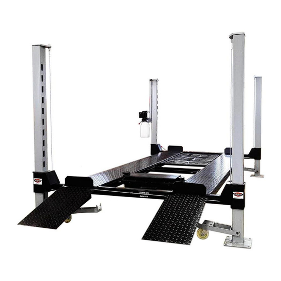
9000lb. Capacity
Models:WF9000
4 Post Parking Lift
WF9000XLT
SHIPPING DAMAGE CLAIMS
When this equipment is shipped, title passes to the purchaser upon receipt from the carrier. Consequently,
claims for the material damaged in shipment must be made by the purchaser against the transportation
company at the time shipment is received.
BE SAFE
Your new lift was designed and built with safety in mind. However, your overall safety can be increased
by proper training and thoughtful operation on the part of the operator. DO NOT operate or repair this
equipment without reading this manual and the important safety instructions shown inside.
Keep this operation manual near the machine at all times. Make sure that ALL USERS read this manual
Advertisement
Table of Contents

Related Manuals for Wildfire WF9000


Summary of Contents for Wildfire WF9000
- Page 1 INSTALLATION & OPERATION MANUAL 9000lb. Capacity Models:WF9000 4 Post Parking Lift WF9000XLT SHIPPING DAMAGE CLAIMS When this equipment is shipped, title passes to the purchaser upon receipt from the carrier. Consequently, claims for the material damaged in shipment must be made by the purchaser against the transportation company at the time shipment is received.
- Page 2 Wildfire 4 post lifts. Here at Wildfire Lifts we feel that cars are more than just a way to get from place to place but instead a piece of history that defines their drivers. We believe every car has its own personality, significance and story which we believe should be shared and properly taken care of.
- Page 3 Rolling Bridge Jack Warranty From the date of purchase by original Purchaser or 12 months from the date of shipment by Wildfire Lifts or whichever comes first. WARRANTY EXTENDS ONLY TO BUYER AND MAY NOT BE REASSIGNED OR TRANSFERRED...
-
Page 4: Important Safety Instructions
INTRODUCTION 1. Carefully remove the crating and packing to report any shipping damage to the carrier materials. CAUTION! Be careful when cutting and make a notation on the delivery receipt. steel/nylon banding material as items may 3. Check the voltage, phase and proper become loose and fall causing personal harm amperage requirements for the motor shown or injury. -
Page 5: Important Notice
MAINTAIN WITH CARE. Keep lift clean for better and safe performance. Follow manual for proper lubrication and maintenance instructions. Keep control handles and/or buttons dry, clean and free from grease and oil. STAY ALERT. Watch what you are doing. Use common sense. Be aware. CHECK FOR DAMAGED PARTS. - Page 6 Installation of the equipment Installation SELECTING SITE : Before installing your new lift, check the following points . Measure to make sure that the assembled lift will fit in desired space including length, width and height. OVERHEAD OBSTRUCTIONS : The area where the lift will be located should be free of overhead obstructions such as heaters, building supports, electrical wires etc.
-
Page 7: Hydraulic Fluid
Four Post Parking Lift WF9000&WF9000XLT 91.81”/101.69” Total Column Height (WF9000/WF9000XLT) Lifting Time ( time may vary based on total loaded weight) 60-90 seconds The Maximum Lifting Height (WF9000/WF9000XLT) 78”/86.6” Rated Load 9000LBS/9000LBS Motor Power 2.2kw Working Voltage 120V20Amp ≤70dB(A) Noise Level... - Page 8 Unpacking Unpacking : Unpack the lift close to the installation site. Open parts box and carefully lay out all your parts. Review your parts list to verify that you have all the parts. Parts Box Models WF9000/WF9000XLT Description Manual Notched Nylon Slider-L (#28BL)
- Page 9 Four Post Parking Lift WF9000&WF9000XLT Step 2: LAYOUT AND POWER UNIT LOCATION Before you begin your assembly, you will want to determine where your lift will be located and the orientation of your power unit. The top runway as packaged contains the hydraulic ram responsible for raising and lowering your lift.
- Page 10 Four Post Parking Lift WF9000&WF9000XLT Step 3: UPRIGHT COLUMN & CROSSBEAM INSTALLATION Remove upright from packaging and place in position on floor. Each upright will be positioned by the laser cut notches. The notches will be positioned as shown above.
- Page 11 Four Post Parking Lift WF9000&WF9000XLT With one person on each side begin sliding the cross beam into place. You will need to hold the secondary lock open, so it does not catch the notches and stop your progress. Once you have carefully slid the cross beam down a foot, lift the cross beam and move the top cap to the opposite side.
- Page 12 Four Post Parking Lift WF9000&WF9000XLT Place the nylon blocks into the 4 corners of each crossbeam. Use the notched nylon slides where the safety locks are located. The notch is there to allow the safety lock to move in and out freely.
- Page 13 Four Post Parking Lift WF9000&WF9000XLT Add slider stops to both sides of each corner post using m16 x 100 hex head bolt, flat washer and lock washer to hold the nylon sliders in place. Step 4: RUNWAY TRACK INSTALLATION Position the runway containing the hydraulic ram in the correct orientation so that this runway is placed on the side that will house the power unit.
- Page 14 Four Post Parking Lift WF9000&WF9000XLT From the backside of the cross beam insert the M12 X 100 mounting bolts through the runway and cross beam. On the outside of the crossbeam attach the approach ramp mounting bracket by attaching to the M12 X 100 mounting bolts you just inserted. Make sure that the approach ramp mounting bracket is attached with the spacer facing the cross beam to allow room for the approach ramp to insert into the gap.
- Page 15 Four Post Parking Lift WF9000&WF9000XLT Step 5: RUNNING AND ATTACHING CABLES With the runways secured, install the 4 top caps. The top cap with the threaded holes will be placed in the corner that will house the motor. This is the runway and corner where the hose connects to the runway.
- Page 16 Four Post Parking Lift WF9000&WF9000XLT Run the cable end up through the post cap. You may need assistance to extend the ram by pushing the ram at the same time as pulling on the cable, this would only be necessary with the first cable. Once the threaded end is fed through the post cap, use the washer and two nuts to lock the cable in place.
- Page 17 On the WF9000 this rod is easily visible, On the WF9000XLT there are 3 small windows, 2 at each end to thread on the safety linkage and 1 in the middle to help guide the linkage rod if necessary.
- Page 18 Four Post Parking Lift WF9000&WF9000XLT Go to the other end of the runway. Before you do anything more you will want to back off the nut for the runway bolt and drop the approach ramp bracket. This will allow you to turn the safety linkage rod handle clockwise until the spacer is flush with the runway or the handle is tight.
- Page 19 Four Post Parking Lift WF9000&WF9000XLT Step 7: INSTALLING PULLEY SAFETY COVERS Using 16 x 100 hex head bolts, flat washer and lock washer, attach the 4 pulley covers as shown in picture. You will need to match up the proper orientation based on what corner you are attaching to.
- Page 20 Four Post Parking Lift WF9000&WF9000XLT Unpack the power unit. At this point you can choose to mount the power unit with or without fluid. The power unit will be easier to lift into position without fluid and can be filled once mounted to the lift. Use the power unit mounting bolts, flat washers and lock washers to mount the power unit.
- Page 21 Four Post Parking Lift WF9000&WF9000XLT Connecting Hydraulic Hoses Attach the hydraulic hose that is running under the runway remove the nut, feed through the hole in the side of runway and use nut to tighten. Note: Before feeding the hose end through the runway make sure fitting is tight.
- Page 22 Four Post Parking Lift WF9000&WF9000XLT Your lift comes with (4) wheel safety stops. These insert at the end of each runway in the same slot as your approach ramps. When using your approach ramps you will need to remove the safety wheel stop.
- Page 23 Four Post Parking Lift WF9000&WF9000XLT loose to allow the axels to travel in/out slightly while transiting the ruwnays. Once the jack tray is in place you can assemble the 2 locks to each side of the tray using the provided hex head fastener kit. Once the lock has been installed, adjust the threaded rod to the necessary spot to allow the lock to hold the tray when engaged.
- Page 24 Four Post Parking Lift WF9000&WF9000XLT Caster Installation and use: When using the casters to move this lift, make sure that you have more than one person to help move and guide the lift. Make sure that the floor space is completely clear of hazards or obstructions.
- Page 25 Four Post Parking Lift WF9000&WF9000XLT Monthly Maintenance • Check safety locks to insure they are in good operating condition. • Check all cables for excessive signs of wear • Make a visual inspection of all moving parts and check for excessive signs of wear •...
-
Page 26: Troubleshooting Guide
Four Post Parking Lift WF9000&WF9000XLT Trouble Shooting Guide Malfunctions Cause Solution Generator does power source power Check up the power fuse, the not work. equipment is malfunctioning. contact in the junction box of motor, micro switch, and the condition of up button, change the damaged part. -
Page 27: Hydraulic Diagram
Four Post Parking Lift WF9000&WF9000XLT Hydraulic diagram Item Name Item Name Item Name Cylinder Overflow valve Gear pump One-way Unloading valve Adjustable throttling overflow valve valve One-way valve Motor Filter... -
Page 28: Explosive Drawing
Four Post Parking Lift WF9000&WF9000XLT Explosive drawing... -
Page 29: Parts List
Four Post Parking Lift WF9000&WF9000XLT PARTS LIST NAME QTY. NAME QTY. Hydraulic Power Unit Nylon Shim Caps Hydraulic Hose L=2000/2200mm Shim Cap Screw Coupler D16 Flat Washer Cable Tensioner-Front Left, Right Hydraulic Hose L=1860/2170mm Rear Cable Tensioner-Front Right, Left Throttle valve... - Page 30 Four Post Parking Lift WF9000&WF9000XLT CABLE ASSEMBLY GUIDE...
Need help?
Do you have a question about the WF9000 and is the answer not in the manual?
Questions and answers