
Related Manuals for MSR INTEC PolyGard 2 MGC6


Summary of Contents for MSR INTEC PolyGard 2 MGC6
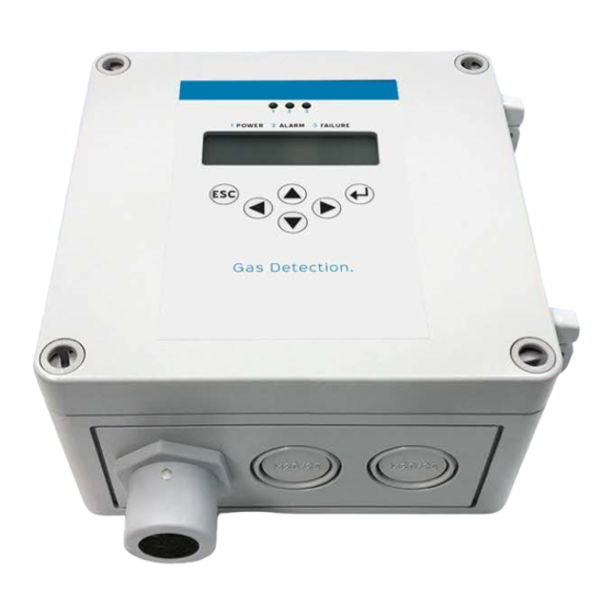
- Page 1 User Manual ® PolyGard 2 MGC6 3-Channel Controller March 27, 2023 August 16, 2023 – Revision INTEC Controls | 12700 Stowe Drive, Suite 100, Poway, CA 92064 | (858) 578.7887 & (888) GO.INTEC | inteccontrols.com...
- Page 2 This page intentionally left blank...
-
Page 3: Table Of Contents
MGC6 – UserManual Specifications subject to change without notice. | GA_MSC2_MSB2_E , 2023-03 | USA 230816 | Page 3 of 28 Table of Contents General ........................... 5 1.1 Applicability ............................5 1.2 Intended Use ............................5 1.2.1 3-Channel Controller MGC6....................5 1.3 Safety ................................ - Page 4 MGC6 – UserManual Specifications subject to change without notice. | GA_MSC2_MSB2_E , 2023-03 | USA 230816 | Page 4 of 28 Operating Modes ........................19 6.1 Restart (Diagnostic and Warm-up Stage) ..................19 6.2 Measuring Mode ..........................20 6.3 Special Mode ............................21 6.3.1 Maintenance and Calibration Mode .................
-
Page 5: General
The product can only fulfil its intended functions if it is installed, used, maintained, serviced and checked in accordance with the instructions provided by MSR-Electronic GmbH | INTEC Controls. INTEC Controls | 12700 Stowe Drive, Suite 100, Poway, CA 92064 | (858) 578.7887 & (888) GO.INTEC | inteccontrols.com... -
Page 6: Responsibilities Of Installers And Operators
If the MGC6 needs to be returned, an authorized RMA number issued by INTEC Controls is required. 1.6 Limited Warranty MSR-Electronic GmbH | INTEC Controls does not assume any liability in case of improper or incorrect use of the device. The installer and operator are exclusively responsible for the design and use of the product. -
Page 7: Functional Description
MGC6 – UserManual Specifications subject to change without notice. | GA_MSC2_MSB2_E , 2023-03 | USA 230816 | Page 7 of 28 2 Functional Description 2.1 General The function of the sensor series AT6 is not subject of this manual but can be read in the User Manual of AT6. -
Page 8: Function Output
MGC6 – UserManual Specifications subject to change without notice. | GA_MSC2_MSB2_E , 2023-03 | USA 230816 | Page 8 of 28 2.2 Function Output Action Reaction Alarm LED Alarm 1 Alarm 2 Alarm 3 Alarm 4 (GS = Gas Signal) Display / Relay 1 Relay 2... -
Page 9: Horn Function (Not Safe Output Circuit Because Resettable)
MGC6 – UserManual Specifications subject to change without notice. | GA_MSC2_MSB2_E , 2023-03 | USA 230816 | Page 9 of 28 2.5 Horn Function (not safe output circuit because resettable) The horn function is considered to be active if at least one of the 2 parameters (time or assignment to digital input) is set. -
Page 10: Installation
MGC6 – UserManual Specifications subject to change without notice. | GA_MSC2_MSB2_E , 2023-03 | USA 230816 | Page 10 of 28 3 Installation Check for completeness and accuracy using the delivery documents and the identification label on the device. Electronics can be destroyed by electrostatic discharge (ESD). Therefore, the installation work should be done only by persons connected to ground, e. - Page 11 MGC6 – UserManual Specifications subject to change without notice. | GA_MSC2_MSB2_E , 2023-03 | USA 230816 | Page 11 of 28 Mounting Procedure: • Open housing cover. • Determine mounting location for AT6 and cable entries on housing. • Break out the required knockouts on the housing bottom part.
-
Page 12: Electrical Connection
MGC6 – UserManual Specifications subject to change without notice. | GA_MSC2_MSB2_E , 2023-03 | USA 230816 | Page 12 of 28 4 Electrical Connection Assembly work must only be carried out under gas-free conditions! Consider static electricity instructions (ESD)! 4.1 General Notes •... -
Page 13: Terminal Connection
MGC6 – UserManual Specifications subject to change without notice. | GA_MSC2_MSB2_E , 2023-03 | USA 230816 | Page 13 of 28 • When choosing the option “Power Supply ≥ 90 VAC” you must make sure that a switch or a circuit breaker is provided in the building automation especially for the unit. -
Page 14: Connection Diagrams
MGC6 – UserManual 5.12 Specifications subject to change without notice. | GA_MSC2_MSB2_E , 2023-03 | USA 230816 | Page 14 of 28 (130) WIRING CONFIGURATION 4.3 Connection Diagrams MGC6 Power Relays drawn de-energized Supply Relay Mode = Energized (Alarm ON= Relay OFF) 24 VDC Relay Relay... -
Page 15: Commissioning
MGC6 – UserManual Specifications subject to change without notice. | GA_MSC2_MSB2_E , 2023-03 | USA 230816 | Page 15 of 28 5 Commissioning 5.1 General Notes All devices without exception run through a complete functional test before delivery. However, transportation, storage, installation or special environmental conditions may lead to (mostly small) deviations. -
Page 16: Registration/Assignment Of At6
MGC6 – UserManual Specifications subject to change without notice. | GA_MSC2_MSB2_E , 2023-03 | USA 230816 | Page 16 of 28 5.4 Registration/Assignment of AT6 The AT6 4–20 mA signal series sensors is detected/monitored. By selecting the signal type (analog or bus), the gas type and the measuring range, the input is activated. The instructions can be found in the User Manual of the Service-Tool STL6. -
Page 17: Checking / Changing Operating Parameters
MGC6 – UserManual Specifications subject to change without notice. | GA_MSC2_MSB2_E , 2023-03 | USA 230816 | Page 17 of 28 5.5 Checking / Changing Operating Parameters The base parameter set is stored in the unit in a fail-safe manner and documented in the enclosed calibration and test protocol. -
Page 18: Running-In Characteristics
MGC6 – UserManual Specifications subject to change without notice. | GA_MSC2_MSB2_E , 2023-03 | USA 230816 | Page 18 of 28 5.7 Running-in Characteristics After switching on or after an internal reset of the microcontroller, the device always runs through a start routine with defined status of the outputs. -
Page 19: Operating Modes
MGC6 – UserManual Specifications subject to change without notice. | GA_MSC2_MSB2_E , 2023-03 | USA 230816 | Page 19 of 28 6 Operating Modes During operation, the unit can assume different operating modes. A distinction is made between the warm-up phase, measuring mode and special mode, whereby special mode is divided into 2 different subcategories. -
Page 20: Measuring Mode
MGC6 – UserManual Specifications subject to change without notice. | GA_MSC2_MSB2_E , 2023-03 | USA 230816 | Page 20 of 28 6.2 Measuring Mode In normal operating mode = measuring mode, there are no faults present, the gas concentration of the sensor is continuously polled, checked for plausibility, output on the analog output (if available) and provided on the field bus. -
Page 21: Special Mode
MGC6 – UserManual Specifications subject to change without notice. | GA_MSC2_MSB2_E , 2023-03 | USA 230816 | Page 21 of 28 6.3 Special Mode 6.3.1 Maintenance and Calibration Mode The operator may set the gas detector in the Special Mode only when gas-free state is ensured (no alarm), because the alarm function is not available in this mode. - Page 22 MGC6 – UserManual Specifications subject to change without notice. | GA_MSC2_MSB2_E , 2023-03 | USA 230816 | Page 22 of 28 Display Fault Analog Field Cause Remedy Relay Output Error Code Text Mess. Sensor Head (AT6) Reaction on Board DP1- Sensor element defective 0x8001h Sensor...
-
Page 23: Maintenance And Service
When carrying out maintenance and repair work according to the user manual, only use original spare parts from MSR-Electronic GmbH | INTEC Controls. Repairs or changes of the warning devices not complying with the maintenance manual or carried out by unauthorized persons can affect proper equipment and safety features and always result in a termination of the manufacturer's warranty and the test certificate. -
Page 24: Maintenance And Calibration
7.3 Maintenance and Calibration New AT6 sensor heads are always delivered factory-calibrated by MSR-Electronic GmbH | INTEC Controls. This is documented by the laser engraving indicating the calibration gas. A repeated calibration is not necessary during commissioning if the device is still in its original packaging (air- tight protection by the red protective cap) and the calibration doesn’t date back more than 12... -
Page 25: Exchange Of Sensor Head
MGC6 – UserManual Specifications subject to change without notice. | GA_MSC2_MSB2_E , 2023-03 | USA 230816 | Page 25 of 28 7.5 Exchange of Sensor Head Instead of performing a field calibration you can simply and comfortably replace the sensor head in the field by a calibrated one. -
Page 26: Project Protection
MGC6 – UserManual Specifications subject to change without notice. | GA_MSC2_MSB2_E , 2023-03 | USA 230816 | Page 26 of 28 Project protection To prevent access to the sensitive calibration data by third parties, every customer receives his own internal project key. All projects of the customer are delivered with this key. The key is also stored in each STL-06 Service-Tool that the respective customer buys. -
Page 27: Configuration Card At6 (Analog Measuring Points)
MGC6 – UserManual Specifications subject to change without notice. | GA_MSC2_MSB2_E , 2023-03 | USA 230816 | Page 27 of 28 Assignment Alarm <> Alarm Relay Assignment Fault <> Alarm Assignment Latching CV-AV CV Delay Alarm (s) Hysteresis Alarm Thresholds Measuring Range Gas Type Locked... -
Page 28: Technical Data
MGC6 – UserManual Specifications subject to change without notice. | GA_MSC2_MSB2_E , 2023-03 | USA 230816 | Page 28 of 28 MGC6 Specifications subject to change without notice. | USA 230808 | Page 2 of 4 10 Technical Data SPECIFICATIONS Electrical Liquid Crystal Display Power supply...
Need help?
Do you have a question about the INTEC PolyGard 2 MGC6 and is the answer not in the manual?
Questions and answers