Table of Contents
Advertisement
Quick Links
Advertisement
Table of Contents

Related Manuals for Lufft SHM31


Summary of Contents for Lufft SHM31
- Page 2 Dear User, Please read this user manual carefully before commissioning the SHM 31 snow depth sensor. We reserve the right to further develop this device in line with technical progress. OTT HydroMet Fellbach GmbH Gutenbergstrasse 20 70736 Fellbach Germany Phone: +49 711 51822-0 Hotline: +49 711 51822-52 Fax:...
-
Page 3: Table Of Contents
Contents 1. Read before commissioning ............................5 Symbols used ..............................5 Safety instructions ............................... 5 Notes on laser safety and laser classification ...................... 5 Intended use ................................ 6 Incorrect use ................................ 6 Brand names used .............................. 6 2. Item names and technical data ..........................7 2.1. - Page 4 9.3.4. Example of a binary protocol query ......................39 9.3.5. Status and error codes in the UMB binary protocol ................40 9.3.6. CRC calculation ............................. 41 10. Communication in SDI-12 mode ..........................42 10.1. Connector pin assignment ..........................42 10.2. Settings for using SDI-12 ..........................42 10.3.
-
Page 5: Read Before Commissioning
Read before commissioning 1. Read before commissioning Please read the operating manual carefully and keep it for future reference. Please note that various components of the device and the described software may look slightly different from the figures provided in this operating manual. -
Page 6: Intended Use
Read before commissioning Maximum radiant output power 0.95 mW Wavelength 635 nm Pulse duration > 400 ps Pulse repetition rate 320 MHz Beam divergence 0.16 mrad x 0.6 mrad Attention Do not look into the laser beam or point the laser beam towards people or animals! Only authorised, trained personnel should have access to the laser sensor. -
Page 7: Item Names And Technical Data
Connection cable (15 m) 8365.KAB015 Reference target plate set 8365.KWK-SET UMB ConfigTool.NET software https://www.lufft.com/download/software-lufft-configtool-net/ Replacement sensor module 8365.30-SEN Table 1: Item numbers 2.1. Labelling The following stickers are attached to the product. Figure 1: Laser warning with technical data Figure 2: Rating plate with serial number Snow depth sensor SHM 31, V2.1... -
Page 8: Technical Data
Item names and technical data 2.2. Technical data Category Name Value Measuring parameters Snow depth 0 – 15 m Accuracy ± (5 mm + 0.06%) Repeatability 0.6 mm Precision, reproducibility 5 mm Signal intensity (normalised) 0 – 255 Installation Assembly height / measuring 0.1 –... -
Page 9: Scope Of Delivery
Item names and technical data Figure 3: SHM 31 dimensions, technical drawing 2.3. Scope of delivery Depending on the order, the delivery consists of the standard scope of delivery (see Figure 4) and additional components (see Figure 5 to Figure 9). Figure 4: Standard scope of delivery 8365.30, consisting of sensor, test report, quick start guide and USB stick with additional software and documents Snow depth sensor SHM 31, V2.1... - Page 10 Item names and technical data SHM 31 8365.30 Mast mount 8365.610-11 Connection cable 8365.KAB015 Figure 5: SHM 31 sensor, here with mast mount 8365.610-11 and connection cable Mast mount 8365.610-11 Figure 6: Mast mount 8365.610-11 Mast mounts with steel strap 8365.608-11 8365.609-11 Figure 7: Mast mount with assembly clamp and steel strap, here for...
-
Page 11: Additional Documents And Software
The software is available for download for the Windows and Android operating systems. In future, it will also be available for individual Linux operating systems. You will find the following documents and software available for download on the internet at www.lufft.com: •... -
Page 12: Description Of The Device
Description of the device 3. Description of the device 3.1. Basic principles of the measurement method The SHM 31 snow depth sensor applies the phase measurement method to precisely measure distances from objects. In the phase measurement method used here, a laser diode emits short laser pulses, which are amplitude modulated with a defined frequency. -
Page 13: Sensor Heating
UMB-ASCII 2.0 protocol (query or automatic transmission mode) or using the UMB binary protocol (pure query mode). Various tools are available here for the UMB binary protocol in particular, such as the Lufft UMB ConfigTool.NET software, as well as connection to other Lufft-specific communication and database solutions such as SmartView. -
Page 14: Generating The Measured Values
Generating the measured values 4. Generating the measured values 4.1. Measured values (curr, avg) Factory setting: The current measured values are measured values averaged over 60 s. A new measurement is performed internally every 10 s. So, for the current measured values, averages are taken and provided for 6 out of these 10 seconds. -
Page 15: Assembly
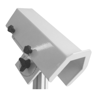
Assembly 5. Assembly 5.1. Assembly instructions Do not look into the laser beam of the SHM 31. Do not switch on the SHM 31 until it has been assembled and aligned. 5.2. Assembly The snow depth sensor is mounted on a mast using the mast clamps provided. The sensor is aligned in the direction of the surface. - Page 16 Assembly Figure 14: Sensor assembled with hood. After attaching the Figure 13: Assembling the connection cable on the sensor. The cable, the weatherproof protective hood is fixed again using strain relief sleeve is inserted into the recess in the base plate the three knurled screws.
-
Page 17: Connections
Connections 6. Connections There is an 8-pin plug-in screw connector on the device’s housing. It is used to connect the supply voltage and the data interface. A connection cable measuring 15 m long is offered separately. 6.1. Connecting the device Figure 16: Connection cable (schematic), designation of the Figure 17: View of soldered connection of connector:... -
Page 18: Commissioning
Lufft website https://www.lufft.com/download/software-lufft-configtool-net/. The software contains a Help function that provides further explanations on using the software. A quick start guide specifically for the SHM 31 forms part of this operating manual. Laser safety • Do not look into the laser when the sensor is switched on. To ensure that the laser is transmitting periodically, use a sheet of paper, for example, and hold it in the laser beam. - Page 19 Commissioning Figure 18: Cogwheel icon to access the settings (start screen) b) If necessary, create or select the folder that ConfigTool.NET should save the log file for your measurements in. c) Use the device template download function to update the list of available UMB channels.
- Page 20 Commissioning 3. You can set up different workspaces in ConfigTool.NET to manage your sensor settings and measurements. You can access the workspace options by clicking on the button in the top left-hand corner of the start screen. a) Click on the ‘Edit Workspaces’ icon. This creates a new workspace if no already created workspace has been selected in the drop-down list.
- Page 21 Commissioning d) On the ‘Workspace Details’ page, enter any name for the workspace first of all. To assign a sensor to the new workspace, click on ‘Add Device’: Figure 22: Various workspaces can be set up in the ‘Workspace Details’ e) In the ‘Add Device’...
- Page 22 Commissioning Figure 24: The added sensors can be selected for additional settings on the ‘Workspace Details’ page h) The following steps are necessary to calibrate the device for use after setup. Click on the cogwheel icon to go to the ‘Device settings’ page. Figure 25: You can access the device’s settings from the ‘Device Details’...
- Page 23 Commissioning Figure 26: The SHM 31 is calibrated in the ‘Calibration’ menu You can now make additional sensor settings. The ‘Transmission interval [s]’ parameter can be found in the ‘UMB-ASCII 2.0’ section of the ‘Device Settings’ page. This value determines how often the sensor will provide new snow depth data.
- Page 24 Commissioning Figure 27: The ‘Device Settings’ menu k) To check the sensor’s functionality, you can select all the channels that ConfigTool.NET can read. These channels are displayed as soon as you click on ‘Load channel list’: For an initial sensor check, we recommend selecting channels 500, 600, 650, 660, 700 and 800.
- Page 25 Commissioning Figure 28: Basic settings for log files and communication with the sensor 4. ConfigTool.NET has now prepared columns for the sensor channels’ measured values on the start screen. All channels previously selected in the ‘Device Details’ menu should already be visible there. In the ‘Query rate’ drop-down menu on the right-hand side, you can now set how often measured values are to be queried from the sensor.
-
Page 26: The Shm 31'S Sensor Parameters
Commissioning 7.3.2. The SHM 31’s sensor parameters To take full advantage of all the benefits the SHM 31 snow depth sensor has to offer, we recommend taking a closer look at the parameters the sensor uses internally. As already mentioned in the previous section, the ‘Device Settings’ menu contains a large number of adjustable parameters and thus also a comprehensive tool for defining a measurement routine for the sensor in advance. - Page 27 Commissioning Hysteresis for window heating 0 … 5 Switching point below (heating on) and [°C] above (heating off) target temperature Hysteresis for block heating [°C] 2.5 0 … 5 Switching point below (heating on) and above (heating off) target temperature Voltage threshold of heating [V] 17 12 …...
- Page 28 Commissioning Use 10000 as value for installation to prevent error messages due to vast changes in measured distances (e.g. due to obstruction). Accept time for changed snow 0 … 65535 Time interval for the snow depth value depth [s] to be accepted, allthough exceeding the sensors maximum snow depth change rate Laser parameters...
-
Page 29: Communication Over Umb-Ascii 2.0
Communication over UMB-ASCII 2.0 8. Communication over UMB-ASCII 2.0 This section describes the communication and output of measured values of the SHM 31 over the UMB- ASCII 2.0 data protocol. Communication is available over the RS232 and RS485 interfaces. 8.1. Syntax The parts in the square brackets are optional: Request <Add>:<No>:<Payload><CR><LF>... -
Page 30: Description Of The Data Telegram #1 With An Example
Communication over UMB-ASCII 2.0 (Channel busy) B001:4E:CHN;523<CR><LF> <STX>B001:4E:CHN;523:24:<CheckSum><CR><LF><EOT> (Channel unknown) 8.4. Description of the data telegram #1 with an example <Add>:<Nr>:Payload:UMB status:checksum data telegram B001:4E:SS;1=085;003.0117;+02.1253;185;+15;17.8;15:00:8E Example Length in bytes Description B001:4E:SS;1= Repeat request command, address, ... Telegram number Delimiter, user adjustable 003.0117 First 8 digits of the serial number Delimiter, user adjustable... -
Page 31: Ascii Command Overview
23 ASCII2_INFO_CHAN_DATATYPE • 24 ASCII2_INFO_CHAN_TYPE 30 ASCII2_INFO_CHAN_INFO • *) Remark: requires an additional parameter which defines which part (block) of the channels should be transmitted. There are 4 blocks for the SHM31. Example: ...IFO;16;0 Command Standard Read, write, Name Description UMB-ASCII 2.0... - Page 32 Communication over UMB-ASCII 2.0 Command Standard Read, write, Name Description UMB-ASCII 2.0 value command Starts the automatic snow depth MeasurementStart measurement Standard-Set, Requests the current telegram SS<;> <SS-Nr> Telegram Format (standard format 1) Repetition rate of measurements AutoTransmitInterv (calculation of snow depth, prepare telegram and send if applicable) 0=polling, 1,2,..=telegram format AutoTransmitMode...
- Page 33 Communication over UMB-ASCII 2.0 Read, Command Standard Write, Name Description UMB-ASCII 2.0 value Command the telegram are converted to the new units. The scaling factor is defined in the range [0;40000]. User-Interface RS485/SDI-12 (0=UMB, 9=ASCII2.0, 3=SDI-12, 5=Modbus- Protocol RTU, 6=Modbus-ASCII) Boot up mode of the sensor, e.g.
- Page 34 Communication over UMB-ASCII 2.0 Read, Command Standard Write, Name Description UMB-ASCII 2.0 value Command Signal calibration for targets Adj.SignalHighRelfectivity with 85% reflectivity in 5 ASH<;><Nr> <#> corresponds to the distances, <#> = [1..5] distances (1=a, 2=b, …, 5=e) Signal calibration for targets Adj.SignalLowReflectivity with 6% reflectivity in 5 ASL<;><Nr>...
- Page 35 Communication over UMB-ASCII 2.0 Read, Command Standard Write, Name Description UMB-ASCII 2.0 value Command Hysteresis; temperature is kept within this range in the HeaterWindowHysteresis automatic heater mode (“HBM“=1). Start defrost mode temporarily (with values “HDP”, “HDR”, “HDB”, “HDW” HeaterDefrostStart for both heaters (block and window)).
- Page 36 Communication over UMB-ASCII 2.0 Choose tilt angle mode, 0=use reference angle “AAN”, Use Accelerometer Angle 1=use currently measured value of the inclination sensor. Maximally allowed difference between two snow depth measurements. The factory set value is 0.02 m. During installation it is recommended to set the value to 10 m to Maximal SnowDepth simplify the installation and...
-
Page 37: Umb Communication
° x-angle ° y-angle ° z-angle ° tilt angle reference ° Table 12: Measuring channels SHM31: 100 – 599 (float 32 data type) UMB channel Measured variable (float32) Unit snow depth snow depth snow depth snow depth inch distance... - Page 38 4100 uint8 shm30 code Error! are listed in table Reference source not found. shm31 error (current) 4101 uint8 shm30 code internal error handling Table 14: Measuring channels 700 – 4999 UMB channel Measured variable...
-
Page 39: Communication In Binary Protocol
UMB ConfigTool.NET. Please refer to the UMB protocol manual, if desired, for a general description of communication in the UMB binary protocol over the RS485 interface. The description of the UMB protocol can be downloaded from the Lufft website at www.lufft.com. 9.3.1. -
Page 40: Status And Error Codes In The Umb Binary Protocol
UMB communication Sensor: The target address for the SHM31 is B001h. The class ID for the PC (master unit) is 15 = Fh; the PC ID is e.g. 001d = 01h. Putting the class and device IDs together gives a sender address of F001h. -
Page 41: Crc Calculation
UMB communication 9.3.6. CRC calculation The CRC is calculated according to the following rules: Norm: CRC-CCITT Polynomial: 1021h = x + 1 (LSB first mode) Start value: FFFFh For more information, see the description of a CRC calculation in the UMB protocol. Snow depth sensor SHM 31, V2.1... -
Page 42: Communication In Sdi-12 Mode
Communication in SDI-12 mode 10. Communication in SDI-12 mode Communication in SDI-12 mode corresponds to the: ‘SDI-12: Serial-Digital Interface Standard Microprocessor-Based Sensors – Version 1.3 – January 12, 2009’. SDI-12 v1.4 is also supported as of firmware version v16. The SHM 31-UMB can be operated in Bus mode with other SDI-12 sensors on an SDI master (logger). -
Page 43: Command Overview
Communication in SDI-12 mode 10.4. Command overview Details about the SDI-12 protocol can be found in the above-mentioned standard document. Of the commands listed there, the following are available for the SHM 31-UMB: In the examples in the following sections, logger queries are always shown in italics ( 0V! ) Command Function Address search (Wildcard request, one device only on bus!) -
Page 44: Setting The Address
Communication in SDI-12 mode Due to the measurement methods used, the SHM 31 sensors always measure continuously, unlike the standard sensors described in the SDI-12 documents. As a result, this operating mode has some special features: The device does not need to be ‘woken up’ and does not have a sleep mode. Data retrieved with M or C commands is always available immediately. -
Page 45: Example: C And M Queries Of The Shm 31-Umb
If “MEN” has been set (MeasurementEnd, 10.11.3) 0D1! 0+51.5+12+11.9+0<CR><LF> Laser temperature 51.5°C, normalised signal 12, tilt angle 11.9°, SHM31 error status 0 If “MEN” has been set (MeasurementEnd, 10.11.3) 0+0.0+0+0.0+67<CR><LF> 10.6.2. Buffer assignment – basic data – SHM 31-UMB Measurement Value... -
Page 46: Additional Measuring Commands
(cur) code signal normalized Buffer ‘1’ distance -500.0 21000.0 SHM31 error 4100 code Table 8: SDI-12, additional values (M1 / C2: Flags) configured in metric units. The fog flag is not calculated at present. Snow depth sensor SHM 31, V2.1... -
Page 47: Device Identification Telegram
Buffer ‘1’ distance -19.7 826.8 SHM31 error 4100 code Table 9: SDI-12, additional values (M1 / C2: Flags) configured in US units. The fog flag is not calculated at present. 10.8. Device identification telegram The device identification query is answered with the following telegram (example of SDI-12 device address ‘0’:... -
Page 48: Query Measured Value Parameter Command (Sdi-12 V1.4)
CHANNEL_OVERRANGE VALUE_UNDERFLOW CHANNEL_UNDERRANGE BUSY Other sensor status Table 10: SDI-12, sensor status coding (for more information, also see documentation on the Lufft UMB protocol) Example (SHM 31-UMB, SDI-12 address ‘0’, no errors): 00002<CR><LF> 0D0! 0+0000+0000<CR><LF> Example (SHM 31-UMB, SDI-12 address ‘0’, laser temperature measurement failed): 00002<CR><LF>... -
Page 49: Switching Commands
Communication in SDI-12 mode Snow height DSTC Calibrated distance Snow flag Fog flag Normalised signal strength SHM31 error DSTA Device status STA1 Sensor status 1 STA2 Sensor status 2 System time at request Example: 0IM_002! 0,HSN,mm,cur<CR><LF> 10.11. Switching commands Switching commands are implemented as manufacturer-defined SDI-12 ‘extended’ telegrams and are used to trigger procedures. -
Page 50: End Measurement Command
Communication in SDI-12 mode Example: 0XRES! 0XRESok<CR><LF> 10.11.3. End measurement command The command ends the automatic snow depth measurement, e.g. for setting and calibration work. Command: aXMEN! Response: aXMENok<CR><LF> If procedures that prohibit execution of the command are active, aXMENbusy<CR><LF> will be the response and the command will be ignored. -
Page 51: Calibrate Offset Command
Communication in SDI-12 mode 10.11.8. Calibrate offset command The command starts a measuring process to determine the distance. The determined values are set as offsets / reference heights using the stored reference angle. Command: aXARH! Response: aXARHok<CR><LF> If procedures that prohibit execution of the command are active, aXARHbusy<CR><LF>... -
Page 52: Setting The Parameter Setting
Communication in SDI-12 mode 0XPLMI+5000<CR><LF> 10.12.2. Setting the parameter setting Command: aXPccc<+/->nnn! aXPccc<+/->fff.f! ccc: Three-character parameter code; see table nnn, fff.f: Parameter value to be set, number of digits as required The entry can be made both as an integer and as a floating point number, regardless of the parameter’s number type, and the value is rounded if necessary. -
Page 53: Communication In Modbus Mode
Communication in Modbus mode 11. Communication in Modbus mode To make integrating the SHM 31-UMB into PLC environments easier, communication according to the Modbus protocol is provided. The measured values are mapped to Modbus input registers. Essentially, the same range of measured values is available as in the UMB protocols, including the conversion to different systems of units. - Page 54 Communication in Modbus mode When writing to a parameter register, the new value is entered into the permanent memory, but is only active after a device reset. In other words, the register only supplies the new value when read after a reset. The value to be written is checked to ensure it is permissible. If the set limits are exceeded, the sensor responds with an ‘Illegal Data Value’...
-
Page 55: 0X04 Read Input Registers Function
Communication in Modbus mode Maximum snow Maximum accepted snow height height difference difference between two measurements [mm] Range: -20000 … +20000 Laser operating Not yet implemented mode Range: 0 Laser measurement Laser mesurement interval [msec] interval Range 1000 … 60000 Values less than 5000ms are not recommended! 11.3.2. - Page 56 Communication in Modbus mode SHM31 error code (see chapter 13.3.3) SHM31 error code (cur) (see chapter 13.3.3) Accumulated operating time lower 16bit of attended time [sec] Accumulated operating time upper 16bit of attended time [sec] System time lower 16bit of system time [sec]...
- Page 57 Communication in Modbus mode Block temperature °C (max) Range: -400 … 1000 → -40.0 … 100.0 Block temperature °C (avg) Range: -400 … 1000 → -40.0 … 100.0 Ambient temperature °C (cur) Range: -500 … 1000 → -50.0 … 100.0 Ambient temperature °C (min) Range: -500 …...
- Page 58 Communication in Modbus mode Normalized signal (max) Range: 0 … 255 Normalized signal (avg) Range: 0 … 255 reserved reserved reserved reserved Service channels Status block heating 0 = Heating off 1 = Heating on Internal NTC temperature °C Range: -400 …...
-
Page 59: Checking The Signal Quality
Checking the signal quality 12. Checking the signal quality (Instructions for using the target plate set 8365.KWK-SET) The sensor’s signal quality can be checked at the measuring location with the help of the target plate set. The set consists of the following DIN A4-sized, high-quality plastic plates: •... - Page 60 Checking the signal quality A basic measurement setup is shown in Figure 31. Figure 31: Checking the signal quality with the white card 8365.KWK-WS The measurements shown in Figure 30 were obtained with the measurement setup shown in Figure 31. The domain for the signal intensity (signal normalised) is between 0 and 255.
-
Page 61: Service, Maintenance And Technical Support
To keep the sensor up to date with the latest technology, we recommend regularly checking whether new firmware is available for the SHM 31 sensor. You can obtain the firmware from lufft.com/en-gb/downloads. You can conveniently perform the firmware update on site with the UMB ConfigTool.NET software. - Page 62 Service, maintenance and technical support If the glass pane of the transmitter / receiver is dirty, clean it with a damp, wrung-out cloth. Then dry the panes with a dry, lint-free cotton cloth. Also remove dust and dirt from the housing. Do not use solvents such as cleaning solvent, thinner, alcohol, kitchen cleaners, etc., to clean the sensor, as these products can damage the housing and the optical parts.
-
Page 63: Faults
Service, maintenance and technical support 13.3. Faults 13.3.1. Possible indications of error on the snow depth sensor Description of error Cause and remedy The device cannot be queried or is not • Check the supply voltage responding • Check the cable •... -
Page 64: Umb Status Codes
Service, maintenance and technical support Error codes Description Hardware error in the interface Incorrect value in the interface communication (SIO parity error) SIO overflow; check time for output signals in application software SIO framing error; serial interface parameter not set correctly to 8N1 Evaluation routine: In some cases, measurements in the calculation interval were ignored because they would have exceeded the maximum permitted change in snow depth. -
Page 65: Disposal Information - Within The Eu
Service, maintenance and technical support 13.5. Disposal information – within the EU The device must be disposed of in accordance with European Directive 2012/19/EU and national regulations. Electrical devices marked with this symbol must not be disposed of in European household or public waste disposal systems. Return old or used devices to the manufacturer for disposal free of charge.
Need help?
Do you have a question about the SHM31 and is the answer not in the manual?
Questions and answers