Table of Contents
Advertisement
Quick Links
SFA Companies
E-mail: sales@bvahydraulics.com
!
This is the safety alert symbol. It is used to alert you to potential personal injury hazards.
Obey all safety messages that follow this symbol to avoid possible injury or death.
Maximum Operating Pressure 10,000 PSI
PW2
Model No. D0904
PW33L
MODELS: PW2, PW3, PW4, PW33L, PW43L
10939 N. Pomona Ave. Kansas City, MO 64153
Tel: 888-332-6419
PW3
Drawn By: 蔡弼任
Pump Mounted
Manual Control Valves
Instruction Manual
-
Fax: 816-448-2142
Website: www.bvahydraulics.com
Model No. D0900
PW43L
PW2-M0_012018
PW4
Drawn By: 蕭益彰
Printed in Taiwan
Advertisement
Table of Contents

Related Manuals for BVA Hydraulics PW2


Summary of Contents for BVA Hydraulics PW2
- Page 1 PW2-M0_012018 Pump Mounted Manual Control Valves Instruction Manual MODELS: PW2, PW3, PW4, PW33L, PW43L SFA Companies 10939 N. Pomona Ave. Kansas City, MO 64153 Tel: 888-332-6419 Fax: 816-448-2142 E-mail: sales@bvahydraulics.com Website: www.bvahydraulics.com This is the safety alert symbol. It is used to alert you to potential personal injury hazards.
-
Page 2: Hydraulic Cylinders
Save these instructions. For your safety, read and understand the information contained within. The owner and operator shall have an understanding of this device and safe operating procedures before attempting to use this device. Instructions and safety information shall be conveyed in operator's native language before use of this device is authorized. Make certain that the operator thoroughly understands the inherent dangers associated with the use and misuse of the product. -
Page 3: Product Description
2. Verify that the product and the application are compatible. If in doubt, call BVA Hydraulics Technical Service (888)332-6419. 3. Inspect before each use. Do not use if broken, leaking or damaged components are noted. - Page 4 PUMP MOUNTED DIRECTIONAL CONTROL VALVE DIAGRAM Valve Valve Use with Model Hydraulic Symbol Schematic Flowpath Operation Type Cylinder Advance Hold Retract 3-way, Single- Tandem Acting Center 4-way, Double- Tandem Acting Center 3-way, 3-position, Single- Tandem PW33L Acting Center, Locking Pump 4-way, Mounted, 3-position,...
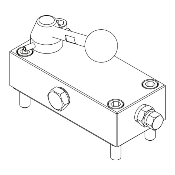
- Page 5 Pump Mounted Control Valve Service Parts MODEL: PW2 SFA Companies 10939 N. Pomona Ave. Kansas City, MO 64153 Tel: 888-332-6419 Fax: 816-448-2142 E-mail: sales@bvahydraulics.com Website: www.bvahydraulics.com Note: Not all components of the valve are replacement items, but are illustrated as a convenient reference of location and position in the assembly sequence.
- Page 6 Pump Mounted Control Valve Service Parts SFA Companies 10939 N. Pomona Ave. Kansas City, MO 64153 Tel: 888-332-6419 Fax: 816-448-2142 E-mail: sales@bvahydraulics.com Website: www.bvahydraulics.com Note: Not all components of the valve are replacement items, but are illustrated as a convenient reference of location and position in the assembly sequence.
- Page 7 Pump Mounted Control Valve Service Parts SFA Companies 10939 N. Pomona Ave. Kansas City, MO 64153 Tel: 888-332-6419 Fax: 816-448-2142 E-mail: sales@bvahydraulics.com Website: www.bvahydraulics.com Note: Not all components of the valve are replacement items, but are illustrated as a convenient reference of location and position in the assembly sequence.
- Page 8 Pump Mounted Control Valve Service Parts PW33L SFA Companies 10939 N. Pomona Ave. Kansas City, MO 64153 Tel: 888-332-6419 Fax: 816-448-2142 E-mail: sales@bvahydraulics.com Website: www.bvahydraulics.com Note: Not all components of the valve are replacement items, but are illustrated as a convenient reference of location and position in the assembly sequence.
- Page 9 Pump Mounted Control Valve Service Parts PW43L SFA Companies 10939 N. Pomona Ave. Kansas City, MO 64153 Tel: 888-332-6419 Fax: 816-448-2142 E-mail: sales@bvahydraulics.com Website: www.bvahydraulics.com Note: Not all components of the valve are replacement items, but are illustrated as a convenient reference of location and position in the assembly sequence.
- Page 10 Locking Valve Assembly Service Parts PART: D09-4-1006-102 SFA Companies 10939 N. Pomona Ave. Kansas City, MO 64153 Tel: 888-332-6419 Fax: 816-448-2142 E-mail: sales@bvahydraulics.com Website: www.bvahydraulics.com Note: Not all components of the device are replacement items, but are illustrated as a convenient reference of location and position in the assembly sequence.
- Page 11 Locking Valve Assembly Service Parts PART: D09-4-1004-108 SFA Companies 10939 N. Pomona Ave. Kansas City, MO 64153 Tel: 888-332-6419 Fax: 816-448-2142 E-mail: sales@bvahydraulics.com Website: www.bvahydraulics.com Note: Not all components of the device are replacement items, but are illustrated as a convenient reference of location and position in the assembly sequence.
-
Page 12: Lifetime Limited Warranty
• BVA Hydraulics’ liability in all cases is limited to, and will not exceed the purchase price paid for the product. SFA Companies 10939 N.
Need help?
Do you have a question about the PW2 and is the answer not in the manual?
Questions and answers