
Related Manuals for ECO POWER CIPR-250W

Summary of Contents for ECO POWER CIPR-250W
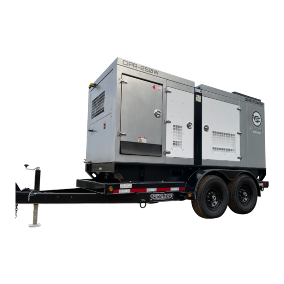
- Page 1 Installation and User Instructions CIPR-250W Natural Gas Generator Mobile Gaseous Generator May 2023 Version 4.1...
- Page 2 Neither Eco Power Equipment Ltd. nor any of its affiliates or subsidiaries shall be responsible or liable for misuse of the information that is contained herein. If you have any suggestions for improvements or amendments or have found errors in this publication, please notify us.
- Page 3 TRADEMARKS Eco Power Equipment Ltd. has made every effort to supply trademark information about company names, products, and services mentioned in this manual. Trademarks shown below were derived from various sources. All trademarks are the property of their respective owners.
-
Page 4: Table Of Contents
Table of Contents 1 Preface 1.1 Description of the User 1.2 Conventions Used in This Manual 1.3 Explanation of Safety Warnings 1.4 Retaining Instructions 1.4.1 Internet 1.4.2 Ordering Documentation 1.4.3 Other Languages 1.4.4 Documentation Feedback 1.4.5 Support and Service 2 Description of the product 2.1 Intended Use and Reasonably Foreseeable Misuse 2.2 Product Elements 2.3 Understanding the User Interface and Control Panel... -
Page 5: Preface
1 Preface 1.1 Description of the User Welcome to the Eco Power Equipment CIPR mobile power generator operator's manual. This manual is designed to assist end-users in utilizing our product for temporary and prime rated power solutions in a variety of applications. The CIPR generator is an ideal solution for generating power, and is commonly used on construction job sites, oil and gas job sites, pipelines, events, security, and government or military operations. -
Page 6: Explanation Of Safety Warnings
URLs, complete paths, filenames, prompts, and syntax 1.3 Explanation of Safety Warnings Danger indicates a hazard with a high level of risk which, if not avoided, will result in death or serious injury Warning indicates a hazard with a medium level of risk which, if not avoided, could result in death or serious injury. -
Page 7: Internet
1.4.4 Documentation Feedback If you are reading Eco Power Equipment Ltd. product documentation on the internet, any comments can be submitted on the support website. Comments can also be sent to support@ecopowerequip.com We appreciate your comments. 1.4.5... -
Page 8: Description Of The Product
2 Description of the product 2.1 Intended Use and Reasonably Foreseeable Misuse The Eco Power Equipment CIPR Mobile Generator is a versatile power solution, featuring a gaseous generator, control panel, and protective sheet metal enclosure mounted on either a trailer or skid for easy transportation. - Page 9 This machine has been designed and constructed in compliance with the most recent Canadian safety standards. It features protective guards and clear labeling to minimize hazards and enhance operator safety. However, despite these precautions, residual risks may persist. Potential hazards associated with this machine include: ●...
- Page 10 Enclosure / Skid Unit Unit Gross Weight 3806 KG / 8368 LBS Lifting Bail Yes, Engineered and Rated, See Decal Enclosure Powder Coated Carbon Steel Control AGC 150 Control Panel Nema 3R Generator End Unit ECO38-2L Make / Model Mecc Alte, Voltage 480V Three Phase, High Wye, Dedicated Main Circuit Breaker...
-
Page 11: Product Elements
Oil Capacity 30 Litres Oil Type API/CD/CF 15W-40 Low Ash 250 kW Gross NG Standby Power Rating Gross LP Standby Power Rating 150.9 kW Gross NG Prime Power Rating 234.1 kW Gross LP Prime Power Rating 150.9 kW Power Rating 1,2,3 Per ISO 3046 at the Flywheel 2.2 Product Elements... -
Page 12: Understanding The User Interface And Control Panel
2.3 Understanding the User Interface and Control Panel The main user interface is within the main control panel door. The control panel consists of a series of toggle switches and a graphical user interface to provide control of all operating systems - and provide the user with operating parameters. -
Page 17: Setup Process
Note: Be sure to fill out and complete the Eco Power Equipment new application form, and ensure to check and verify all aspects of the equipment and application. It is the responsibility of the user to ensure that the equipment is ready for operation. -
Page 18: Operation
15. Visually inspect the engine for leaks, and examine belts, electrical connections, and wiring outside the generator enclosure. 16. Inspect all electrical connections; repair or replace any damaged or worn connections, including external cords connected to the load. Follow local guidelines and best practices for safe electrical practices. -
Page 19: How To Use The Product Safely
● Avoid operating the generator if there are visible signs of wear or damage. ● Ensure proper training for anyone operating the machine. ● Do not modify the equipment without written consent from Eco Power Equipment. -
Page 20: Technical Lifespan
Technical Lifespan ● Gaseous Engine: 20,000+ hours ● Eco Power recommends implementing a regular inspection process to ensure the generator's longevity and successful operation. This product is designed to run on pipeline-quality natural gas or propane gas (HD5 or better). 2.5.3 Personal Protective Equipment ●... - Page 21 ● Inspect the towing hitch and safety chains for secure connections. ● Verify that all lights, brakes, and signals are functioning correctly. 4. Electrical Connections: ● During each deployment, inspect all electrical connections, both internal and external. Mobile units that travel over rough terrain cause cause connections to loosen over time ●...
-
Page 22: Maintenance
3 Maintenance Preventative Maintenance Schedule – Non-EST Interval Interval (Hours) Event Weekl Maintenance Event Number first 50 1500 months hours Check Engine Oil Level Check Engine Coolant Level Check Oil Pressure Check Overall Operating Condition (hose/clamp/pipe/belt/harness/connector) Change Oil and Oil Filter Adjust Valve Lash Spark Plugs (Check/Adjust/Replace) Check Air Filter (Inspect/Replace) -
Page 23: Check Engine Oil
Check Engine Oil Level Check Engine Coolant Level Check Oil Pressure Check Overall Operating Condition (hose/clamp/pipe/belt/harness/connector) Change Weichai and Amsoil Filters Change Oil Adjust Valve Lash Spark Plugs (Check/Adjust/Replace) Check Air Filter (Inspect/Replace) Replace Breather Filter Belts, Pipes, Clamps and Hoses (Inspect/Replace) Check Ignition System (Plug Wires/Coils) Check Coolant Condition * (Sample) -
Page 24: Check Coolant Level
3.2 Check Coolant Level Caution: Never remove the radiator or top tank cap when coolant is hot! Burns and physical harm may occur. A. When coolant is room temperature or below, remove pressurized cap and inspect top tank or radiator for fluid level. B. -
Page 25: Change Oil And Oil Filter
3.4 Change Oil and Oil Filter Note: Recommended oil is: Natural Gas Engines Oil (NGEO); CI-4 or above. Note: For continuous operation in extreme temperatures or in excessively dusty, dirty environments, rely on oil analysis to determine maintenance intervals. Note: For best results, change engine oil while the engine is still warm from operation. 1. - Page 26 8. Using the recommended grade of oil, fill the crankcase with specified quantity. 9. Fill the grease cup of the signal generator with lithium grease (NLGI Gr. 2). 10. Operate engine for five (5) minutes. Check for leaks at filter base and oil pan drain plug during operation.
-
Page 27: Engine Valve Lash Adjustment
3.5 Engine Valve Lash Adjustment Note: Required every 500 hours (1000, 1500, etc.) on non-emergency. Confirm that #1 piston is on the compression stroke by turning both pushrods by hand to verify that both valves are closed. The valves are closed when the push rods are loose and can be turned easily. Engine can be barred over by installing 8mm-1.25 bolts in the six empty holes around the crankshaft pulley and using a pry bar to turn the crankshaft. - Page 28 5. Rotate the crankshaft (360°) until the number 6 piston is on the compression stroke and the timing pointer on the front cover is in line with the “TDC” mark on the vibration dampener. 6. Using Illustration 10, adjust the six (6) valves corresponding with the cylinder 6 “TDC”. Insert the correct feeler gauge between the rocker arm and valve stem tip.
-
Page 29: Inspect Spark Plugs
10. With #6 piston at “TDC” adjust these valves to Exhaust 0.3mm/0.012” / Intake 0.2mm/0.008”. 3.6 Inspect Spark Plugs 1. Inspect high tension leads from coils for shorts, cracking and damage. (if used) 2. Remove/blow out any debris from the cylinder head spark plug hole before removing the spark plug to prevent any debris falling into the combustion chamber. -
Page 30: Fuel System
3.7 Fuel System Bi-Fuel The 4G Engine Controls System has full engine software control authority, therefore switching from Natural Gas (NG) to Propane (LPG/VPG) fuel is a software command from the operator console or a switch input into the 4G ECM. Weichai WP06GNA engine is capable of operating in bi-fuel mode starting from VPG/LPG and switching to NG after the NG pressure develops from operation. - Page 31 Diagnostic Messages The 4G engine control system contains a highly configurable diagnostic list that can be tailored to each application’s specific needs using the calibration spreadsheet. With each available P-code listed along with the short-name description. Note that not all DTCs necessarily apply to every application. ECM: Engine Control Module: 4G 90 pin The ECM is full authority, by this we mean it includes the ignition and air/fuel ratio control, contains all the I/O to interface the engine with the application and has a complete set of diagnostics.
- Page 32 ● It is a continuous fuel flow device. This allows the most homogeneous mixture of air and fuel to the engine yielding optimum combustion with minimum emissions and maximum fuel economy. ● It operates on low pressure fuel from 6 to 20 inches of water of inlet pressure, no pressure intensification system required.
- Page 33 ● Extended diaphragm life through material selection and design ● Performance over the -40 to +125C temperature range ● Eliminate LPG fuel contamination Issues ● Superior low flow resolution and repeatability, eliminates idle adjustment ● Backfire resistant through design enhancements Intake air system The intake system should be sealed between the mixer inlet and the filter.
-
Page 34: Exhaust System
Natural Gas & Wellhead Gas Fuel System The fuel first passes the fuel shut off when the engine starts cranking. Then it goes through the DEPR and comes into the mixer to be mixed with the air from the air filter as shown in Figure 11 Weichai WP06GNA are capable of running the NG or wellhead gas with energy content from 700 to 1800 BTU per cubic foot. - Page 35 Figure 16 UEGO Sensor Installation Post-catalyst Oxygen sensor In general, the sensor installation point must be tested sufficiently by the customer for function and durability. There shall be no possibility of exhaust leaks upstream of the sensor as exhaust pulsations can draw in ambient air, leading to erroneous measurements.
- Page 36 System measures: Never switch on sensor heating before engine starting Delayed switch-on or power control of the sensor heater (e.g. as a function of engine and ambient temperature), so that the max. allowed ceramic temperature is not exceeded when there is condensation water present Installation angle should be inclined at least 10°...
- Page 37 oil, sealing materials etc., and thus reaches the sensor is application specific and must be determined by customer tests. The sensor must not be exposed to strong mechanical shocks (e.g. while the sensor is installed). Otherwise the sensor element may crack without visible damage at the sensor housing. For physical reasons the sensor needs ambient air at its reference gas side.
- Page 38 Operation The continuous operating exhaust gas temperature must be between 1112degF (600°C) and 1562degF (850°C). The Product installer shall take necessary precautions to accommodate shell skin temperatures up to 1202degF (650°C). System back pressure must remain with +/- 5% of nominal conditions. Engine misfires and exhaust stream contaminants are not permissible.
Need help?
Do you have a question about the CIPR-250W and is the answer not in the manual?
Questions and answers