
Related Manuals for Lincoln Electric CWT GFM K3696-1


Summary of Contents for Lincoln Electric CWT GFM K3696-1
- Page 1 For use with machines having Numbers: K3696-1, K3697-1, A0A0161, A0A0162 IM10501-A | Issue D ate Feb-22 © Lincoln Global, Inc. All Rights Reserved.
- Page 3 THANK YOU FOR SELECTING A QUALITY PRODUCT BY KEEP YOUR HEAD OUT OF THE FUMES. DON’T get too close to the arc. LINCOLN ELEC TRIC. Use corrective lenses if necessary to stay a reasonable distance away from the arc. READ and obey the Safety Data PLEASE EXAMINE CARTON AND EQUIPMENT FOR Sheet (SDS) and the warning label DAMAGE IMMEDIATELY...
- Page 4 W117.2-1974. A Free copy of “Arc Welding Safety” booklet E205 is available from the Lincoln Electric Company, 2.d. All welders should use the following procedures in order to 22801 St. Clair Avenue, Cleveland, Ohio 44117-1199.
- Page 5 SAFETY ELECTRIC SHOCK ARC RAYS CAN BURN. CAN KILL. 3.a. The electrode and work (or ground) circuits are 4.a. Use a shield with the proper filter and cover plates to protect your electrically “hot” when the welder is on. Do eyes from sparks and the rays of the arc when welding or not touch these “hot”...
- Page 6 SAFETY WELDING AND CUTTING CYLINDER MAY EXPLODE IF SPARKS CAN CAUSE DAMAGED. FIRE OR EXPLOSION. 7.a. Use only compressed gas cylinders containing the correct shielding gas for the process used 6.a. Remove fire hazards from the welding area. If and properly operating regulators designed for this is not possible, cover them to prevent the welding sparks the gas and pressure used.
- Page 7 EN 60974-10 Electromagnetic Compatibility (EMC) Product Standard for METHODS OF REDUCING EMISSIONS Arc Welding Equipment. It is for use with other Lincoln Electric Public Supply System equipment. It is designed for industrial and professional use.
-
Page 8: Table Of Contents
Table of Contents OVERVIEW ........................1 DESCRIPTION .............................1 BENEFITS ..............................1 FEATURES ..............................1 MECHANICAL SPECIFICATIONS ......................1 SENSOR SPECIFICATIONS ........................2 MODELS ...............................2 OPTIONAL ACCESSORIES ........................2 INSTALLATION ......................3 OPTIONS ..............................3 GAS LINE HOOKUP ............................3 OPTIONAL GAS LINE FILTERS .........................3 CABLE HOOKUP ............................4 GAS FLOW LIMITS ............................5 GAS FLOW VOLUME ..........................5 OPERATION ........................ - Page 9 10.1 GFM ENCLOSURE PARTS LIST ......................20 10.2 GFM MOUNTING DIMENSIONS ......................21 11.0 CABLE SPECIFCATIONS ..................23 11.1 GFM AUX CABLE P/N: A3W0418 ......................23 12.0 MODBUS SCPECIFICATIONS ................... 24 12.1 GFM MODBUS REGISTER DATA ......................24 12.2 MODBUS COILS CR [1..16] ........................24 12.3 MODBUS REGISTER REG [1..10] ......................
-
Page 10: Overview
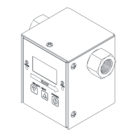
1.0 OVERVIEW Description The Gas Flow Monitor (GFM) is designed to precisely measure the flow rates of welding shielding gases. WARNING – DO NOT USE WITH ANY FLAMMABLE GASES. The unit comes in both "portable" and "in-line" models and is software configurable for English or Metric units of measure. -
Page 11: Sensor Specifications
Sensor Specifications Measurement Range 5 - 255 CFH (2 - 120 LPM) Display Resolution ±1 CFH (± 1 LPM) Accuracy ±3 % of full-scale ±1 digit Operating Pressure 50-PSI maximum (344 KPA) Fault Relay Output Opto-Isolated Solid State Relay (N.O. Contacts) Relay Rating 48 vac @ 0.5 amps non-inductive 48 vdc @ 1.0 amps non-inductive... -
Page 12: Installation
2.0 INSTALLATION Options The GFM can be used as a portable or in-line gas flow monitor. If the unit was purchased as a portable monitor, it will be equipped with a rubber gas cone. When installing the rubber hose and gas cone on the GFM make sure the hose is installed on the side of the GFM marked gas inlet. -
Page 13: Cable Hookup
Recommended Filter Suppliers Manufacture Model Function Pall Corporation Acro 50 • The filter may be used at a common mode pressure of www.pall.com 0.17 MPa (24.6 psi) at a temperature of 80 °C [176 °F] • May be used with swag lock compression fittings •... -
Page 14: Gas Flow Limits
Gas Flow Limits The GFM can be used to test for High/Low gas flow limits. An internal fault relay will be set (CLOSED) when the gas flow is within the programmed limits. The fault relay can be interfaced to an external weld fixture controller. Gas Flow Volume The GFM can also be used to monitor accumulated gas flow and to provide an indication when the volume in a gas cylinder has reached a programmed minimum... -
Page 15: Operation
3.0 OPERATION Firmware Version The GFM is supplied with a plug-in the wall transformer, which powers the GFM and will also charge the optional internal battery. Plug the transformer into a suitable ac receptacle, and connect the power cable into the "POWER" jack located on the bottom panel of the GFM. -
Page 16: Parameters
Parameters The following is the list of the parameters and system configurations that can be modified by the user: • Max Limit= ### - Maximum gas flow Limits. This value is used to set the high fault alarm and disable the output alarm. This value is also used to trigger the Peak Flow detector. - Page 17 • DEVICE ID= - This parameter sets the Modbus address ID number for the GFM. This address is used to identify the Device when using the Modbus® serial communications protocol. Each sensor connected to the Modbus® network must have a unique ID number assigned. (Value Range 1 to 247) •...
- Page 18 • 80/20 Argon/ CO Gas? - Allows the user to enable or disable 80/20 Argon/ Gas conversion factor. Setting this option to “No” will disable the 80/20 Argon/ CO Gas conversion factor. Setting this option to “Yes” will enable the 80/20 Argon/ CO Gas conversion factor.
-
Page 19: Setting Gas Flow Control Limits
4.0 SETTING GAS FLOW CONTROL LIMITS Description To use the GFM as a Sure-Flow gas switch, the user can set the “Max Limit” and “Min Limit”. The GFM will activate the internal fault relay as long as the gas flow remains above the lower limit and below the upper limit. -
Page 20: Gas Flow Surge "Peak" Measurement
5.0 GAS FLOW SURGE “PEAK” MEASUREMENT Description The GFM has a peak value "sample and hold" feature. This allows the user to measure the maximum gas flow rate, which occurred during the welding cycle. The maximum value is the result of a gas surge, which occurs when the gas solenoid is activated. -
Page 21: Gas Flow Usage Log
6.0 GAS FLOW USAGE LOG Description The GFM has a gas flow volume accumulator and gas flow accumulated timer which can be used to display total gas usage and Total gas flow Time. This function allows the user to measure the total cubic ft. or liters of gas used from the last time that the accumulator was reset. -
Page 22: Reset Log Mode Volume
Reset Log mode volume To reset the Log mode volume press both “▼” and "▲" switch simultaneously to enter the “Select Para INC/DEC” mode. The first programmable parameter will appear on the display. To increment through the program menus press the “▲” button. -
Page 23: Gfm Connector Pin Assignment
7.0 GFM CONNECTOR PIN ASSIGNMENT AUX Connector The following is the pin out for the AUX Connector. Pin No. Function 1 (WHT) Modbus RS-485 D+ serial port 2 (BRN) User supplied Power Input VIN+ (12-28 VDC @100 ma) 3 (GRN) CR-A - Will be active when gas flow is within programmed limits. -
Page 24: Power Options And Battery Specification/Changing
8.0 POWER OPTIONS AND BATTERY SPECIFICATION/CHANGING Power Options The GFM can be used as a Battery Powered device or installed in-line and powered from a Plug-in Wall power supply or user supplied 12 - 24 vdc power supply. 8.1.2 Power Board – Revision: A By default the jumper on Header “JP1”... -
Page 25: Battery Specifications
Battery Specifications The portable GFM is supplied with an internal, rechargeable battery. The battery will operate the GFM continuously for approximately 24 hours when fully charged. The supplied plug-in the wall transformer will recharge the battery in approximately 8-10 hours. The GFM can be operated while charging the battery. The battery charge status is displayed by the “CHRG”... -
Page 26: Changing The Battery
Changing the Battery 1. To open the unit, remove the six screws on the back cover of the unit. Carefully lift the cover off. 2. How to remove the battery: 3. Disconnect the two circuit plug of the battery from J3 Battery Header on the Power Board. -
Page 27: Model Specifications
9.0 MODEL SPECIFICATIONS 120/240 VAC Portable GFM System P/N: A0A0161 ITEM PART NO DESCRIPTION SEE 10.1 GFM Enclosure Assembly A3W0278 Rechargeable Battery A2M0170 Hose/Cone Assembly X3T5089 12VDC Universal Switching Power Supply NSS – Not Sold Separately... -
Page 28: 120/240 Vac In-Line Gfm System P/N: A0A0162
120/240 VAC In-Line GFM System P/N: A0A0162 ITEM PART NO DESCRIPTION GFM Enclosure Assembly A3E0222 GFM Mounting Bar X3T5089 12VDC Universal Switching Power Supply 9SM26677 Fitting Kit (Contains 4A, 4B and 4C) Adaptor Fitting Barb Fitting "B" Size Nut #10-32 x 1/2" Lg. Socket Flat Hd. Screw NSS –... -
Page 29: Gfm Enclosure Specifications P/N: A3A0277
10.0 GFM ENCLOSURE SPECIFICATIONS P/N: A3A0277 10.1 GFM Enclosure Parts List ITEM PART NO DESCRIPTION A3E0220 GFM Enclosure Base A3E0221 GFM Enclosure Cover A3E0219 GFM Enclosure Overlay A3E0179 GFM Display Lens GFM CPU PCB Assembly GFM Power PCB Assembly GFM Display PCB Assembly GFM Sensor Harness Airflow Sensor M3 - 0.5 X 6MM Phillips Pan Head Screw... -
Page 30: Gfm Mounting Dimensions
10.2 GFM Mounting Dimensions DC POWER CONNECTOR 2.812 AUXILARY CONNECTOR 3.500 0.633 2.813 1.188 3/8 NPT 0.757 BOTH SIDES 1.750 2X #10-32 UNF 3/8" DEEP 0.406 1.375 Installation with Threaded Inserts or Free Hanging... - Page 31 DC POWER CONNECTOR 2.812 AUXILARY CONNECTOR 3.500 0.633 2.813 1.188 0.188 3/8 NPT 0.757 BOTH SIDES 1.750 2X Ø0.313 4.750 4.000 0.375 0.750 Installation with Mounting Bar...
-
Page 32: Cable Specifcations
11.0 CABLE SPECIFCATIONS 11.1 GFM Aux Cable P/N: A3W0418 3 METERS A3W0418 GAS FLOW GAS+ AUX 3M WIRE COLOR FROM DESCRIPTION White Pin 1 Net+ Brown Pin 2 Power In (12 – 28 VDC) Green Pin 3 Relay CR-A Yellow Pin 4 Relay CR-B Grey... -
Page 33: Modbus Scpecifications
12.0 MODBUS SCPECIFICATIONS 12.1 GFM MODBUS REGISTER DATA This document provides the basic Modbus memory map and command structure for the GFM RS- 485 communications port. The GFM supports the Modbus Protocol as specified in the Modicon Technical publications “Modbus Protocol” (intr7.html). The GFM control does not support the Broadcast mode. -
Page 34: Modbus Register Reg [1
12.3 MODBUS REGISTER REG [1..10] REG NO. MNEMONIC FORMAT PARAMETER DESCRITION GASFLOW Gas flow rate MAXLMT Max Gas Flow Alarm Limit MINLMT Low Gas flow Alarm Limit MINVOL #### Low Volume Alarm (Not Enabled) ACCVOL ####.# Accumulated Gas Flow since last reset RTCHR ##### Total Gas Flow hours since last reset... - Page 36 WARNING Do not touch electrically live parts or Keep flammable materials away. Wear eye, ear and body protection. electrode with skin or wet clothing. Insulate yourself from work and AVISO DE ground. Spanish PRECAuCION No toque las partes o los electrodos Mantenga el material combustible Protéjase los ojos, los oídos y el bajo carga con la piel o ropa moja-...
- Page 37 WARNING Keep your head out of fumes. Turn power off before servicing. Do not operate with panel open or Use ventilation or exhaust to guards off. remove fumes from breathing zone. AVISO DE Spanish PRECAuCION Los humos fuera de la zona de res- Desconectar el cable de ali- No operar con panel abierto o piración.
- Page 40 Lincoln Electric for advice or information about their use of our products. We respond to our customers based on the best information in our possession at that time. Lincoln Electric is not in a position to warrant or guarantee such advice, and assumes no liability, with respect to such information or advice.
Need help?
Do you have a question about the CWT GFM K3696-1 and is the answer not in the manual?
Questions and answers