Table of Contents
Advertisement
Quick Links
WARNING:
FIRE OR EXPLOSION HAZARD
Failure to follow safety warnings exactly could result in serious injury, death, or property damage.
• Do not store or use gasoline or other flammable vapors and liquids in the vicinity of this or any other appliance.
• WHAT TO DO IF YOU SMELL GAS
• Do not try to light any appliance.
• Do not touch any electrical switch; do not use any phone in your building.
• Leave the building immediately.
• Immediately call your gas supplier from a neighbor's phone. Follow the gas supplier's instructions.
• If you cannot reach your gas supplier, call the fire department.
• Installation and service must be performed by a qualified installer, service agency or the gas supplier.
Please read this manual BEFORE installing and
operating this fireplace.
INSTALLER: Leave this manual with the appliance.
CONSUMER: Retain this manual for future reference.
Model: AG26i
United States Stove Company
227 Industrial Park Rd.,
South Pittsburg, TN 37380
PH: (800) 750-2723
www.usstove.com
Ce produit peut vous exposer à des agents chimiques, y compris au monoxyde de
carbone, lesquels sont reconnus dans l'État de la Californie comme causant le cancer et
des malformations congénitales ou autres dommages au fœtus. Pour obtenir plus de
renseignements, veuillez consulter le site www.P65warnings.ca.gov
CALIFORNIA PROPOSITION 65 WARNING:
This product can expose you to chemicals including carbon monoxide, which
is known to the State of California to cause cancer, birth defects and/or other
reproductive harm. For more information, go to www.P65warnings.ca.gov
Report # F18-426R1
853795C-1804M
Advertisement
Table of Contents

Related Manuals for Acadia AG26i


Summary of Contents for Acadia AG26i
- Page 1 Model: AG26i WARNING: FIRE OR EXPLOSION HAZARD Failure to follow safety warnings exactly could result in serious injury, death, or property damage. • Do not store or use gasoline or other flammable vapors and liquids in the vicinity of this or any other appliance.
- Page 2 Laboratory: PFS-TECO Laboratories, Clackamas, Oregon Standards: • ANSI Z21.88-2017 /CSA 2.33-2017, Vented Gas Fireplace Heaters • CSA 2.17-2017, Gas-Fired Appliances for Use at High Altitudes • CSA P.4.1-2015, Testing Method for Measuring Annual Fireplace Efficiency This installation must conform with local codes, or in the absence of local codes, with the National Fuel Gas Code, ANSI Z223.1/NFPA 54, or the Natural Gas and Propane Installation Code, CSA B149.1.
-
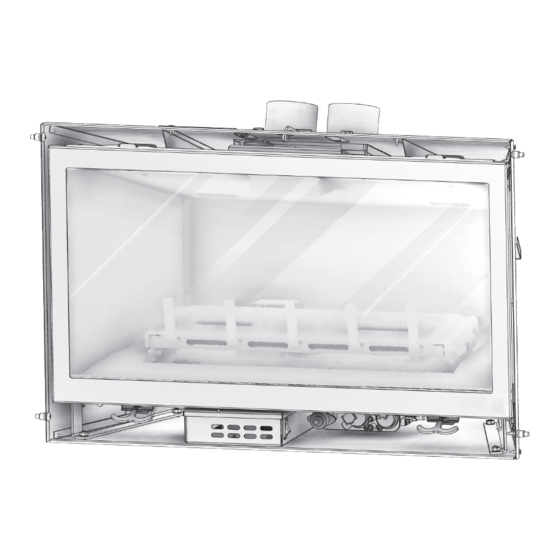
Page 3: Appliance Dimensions
Appliance Dimensions Physical Dimensions Right Side View Left Side View inches Back Width 18 - 3/4 Depth (from back of surround) C Height (to top of exhaust tube) 19 - 5/8 Width 30 - 7/16 Back of Surround to Gas Line Access 7 - 3/4 Bottom to Gas Line Access 1 - 5/8... -
Page 4: Safety Label
Safety Label NOTE: This image is only an example. The label on the actual unit will vary slightly. FOR YOUR SAFETY READ BEFORE OPERATING WARNING: If you do not follow these instructions exactly, a fire or explosion may result causing property damage, personal injury, or loss of life. -
Page 5: Requirements For The Commonwealth Of Massachusetts
Requirements For The Commonwealth Of Massachusetts INSPECTION following requirements reference various Massachusetts and national codes not contained in The state or local gas inspector of the side wall this manual. For all sidewall horizontally vented gas horizontally vented gas fueled equipment shall not fueled equipment installed in every dwelling, building approve the installation unless, upon inspection, the or structure used in whole or in part for residential... -
Page 6: Before You Start
Before You Start WARNING: Read this owner’s manual carefully and completely before trying to assemble, operate, or service. Any change to this appliance or its controls can be dangerous. Improper installation or use can cause serious injury or death from fire, burns, explosions, electrical shock and carbon monoxide poisoning. This is a vented product. -
Page 7: Product Features
17. This appliance, when installed, must be electrically to inspect and if needed replace any part of the grounded in accordance with local codes or in the control system and any gas control which as been absence of local codes, with the National Electrical under water. -
Page 8: High Elevations
Gas Pressures Gas Specifications & Orifice Size Natural Propane (LP) Max. Input Min. Input Orifice Fuel BTU/h BTU/h Size Inlet Minimum 5.0” w.c. 12.0” w.c. Nat. 18,500 10,000 Inlet Maximum 10.5” w.c. 14.0” w.c. Natural Gas LP Gas 17,000 9,000 3/64”... -
Page 9: Chimney Specifications
EXISTING FIREPLACE OPENING MINIMUM REQUIREMENTS inches Height Front Width C Depth Back Width CHIMNEY SPECIFICATIONS WARNING: Any chimney clean-outs must fit properly. This fireplace insert is to be installed into a solid fuel masonry or factory built non- combustible fireplace that has been installed in accordance with the national, provincial, state, and local building codes. -
Page 10: Minimum Termination Clearances
MINIMUM TERMINATION CLEARANCES Inside corner detail Fixed closed Fixed Operable closed Operable Legend: = Vent terminal = Air supply inlet = Air where terminal is not permitted Canadian installation US installations Clearance above grade, veranda, porch, deck, or 12” (30 cm) 12”... -
Page 11: Inspect And Clean Existing Chimney
Installation Preparation NOTE: This gas fireplace insert is approved for installation in masonry and factory-built solid fuel burning fireplaces. CAUTION: Any removed parts must be capable of re-installation if this insert is ever removed. Removal of rivets or screws is acceptable. INSPECT AND CLEAN EXISTING CHIMNEY •... -
Page 12: Installation
Installation CO-LINEAR VENT SYSTEM CAUTION: Proper operation of this insert requires the exhaust and combustion air pipes to be connected to the correct collar, on both the termination kit and the gas fireplace insert air duct. The fireplace insert air duct exhaust is located on the right side. Install termination cap on the right side 1. -
Page 13: Place And Secure Appliance
CONNECT VENT PIPE TO AIR DUCT CAUTION: Proper operation of this appliance requires exhaust and combustion air pipes to be connected to the correct collar, on both the termination kit and the gas fireplace insert air duct. 1. Place previously removed air duct into existing fireplace opening. -
Page 14: Gas Line Connection
Gas Line Connection GAS CONVERSION (SOLD SEPARATELY) CAUTION: The conversion shall be carried out in accordance with the requirements of the provincial authorities having jurisdiction and in accordance with the requirements of the ANSI Z223.1 installation code. This fireplace is manufactured for use with natural gas. Follow the instructions included with the AG26LPC conversion kit if converting to LP gas. -
Page 15: Glass Frame Assembly
Log, Liner, Safety Barrier, & Surround Installation CAUTION: Do not place logs directly over burner port holes. Improper log placement may affect flame appearance and cause excessive soot to build upon the logs and glass. • If converting to LP (propane) gas, complete the conversion before installing the log set. Follow the conversion instructions included with the kit. -
Page 16: Control Board
3. Lift glass assembly up and off of the (2) tabs located at the top of the firebox. INSTALL GLASS ASSEMBLY 1. Align the slots on top of the glass assembly over the tabs at the top of the firebox while lowering the bottom of the glass assembly into position. - Page 17 Wiring Schematics -17-...
-
Page 18: Replacement Parts And Service
Replacement Parts And Service OVER FIRING OF BURNER Never "over fire" adjusting gas pressure or drilling out the orifice to increase Btu/hr above nameplate specifications. Over firing can cause permanent damage to firebox and deterioration of parts and void warranty. MAINTAINING CORRECT PILOT-FLAME The pilot flame must be checked during initial installation and annually by a qualified technician. -
Page 19: Valve Assembly
VALVE ASSEMBLY Pilot Top Shutter Cable Shutter Cable Bulk Head Tube MTG Brkt Gas Pilot Shutter Adjustment Sleeve Pilot MTG Box Burner Orifice Weldment Shutter Adj. Bottom Burner Mount Plate Assembly Shutter Adj. Top Valve Assembly Assembly Mount Burner Accent Light Control Module Blower -19-... -
Page 20: Installation Checklist
Installation Checklist All items on the checklist must be completed. The venting system is installed by an approved service person in accordance with instructions and local codes. Vertical vent cap is installed "right-side-up" and tightly sealed to the structure per instructions. Vent Caps are approved. -
Page 21: Remote Control Functions
REMOTE CONTROL FUNCTIONS You will hear a beep once every time a remote-control button is pressed, LCD Display signaling that the command has been received. Locate the four function On/Off Button buttons on the remote control: Thermostat 1. On/Off Button: This button turns the fireplace on or off. When this Button button is depressed, and the system is off, the pilot will ignite. - Page 22 UNDERSTANDING YOUR REMOTE-CONTROL ICONS Your remote control displays and controls the following functions. See below for detailed control icon explanations. Child Lock Transmission Low Battery Accent Light: This function controls the accent light Room Thermostat functions. Pressing the up button in this mode will turn Temperature Off/On/Smart on the accent light and allow you to control the 6 levels...
-
Page 23: First-Time Lighting Instructions
First-Time Lighting Instructions WARNING: WARNING: If you do not follow these instructions WHAT TO DO IF YOU SMELL GAS exactly, a fire or explosion may result causing • Do not light any fireplace. property damage, personal injury, and loss of life. •... -
Page 24: Where Can I Find The Model And Serial Numbers
This information will expedite the warranty verification process. This is an example of your listing label: DO NOT REMOVE OR COVER THIS LABEL Model / Modéle: AG26i Mfg Date. / Date de Fabrication Serial No. / N de série... - Page 25 ADDITIONAL CURING INFORMATION It is not unusual to require more than 10 continuous hours on high for curing odors to diminish. There are variables that can extend or shorten the curing time, such as decorative fronts, doors, facing materials, and their applications. It is normal for surrounding surfaces to be too hot to touch.
-
Page 26: Burner Flame Appearance
3. Before re-installing glass, have qualified service person check the operation of the pilot and cycle the burner per lighting instructions. Be sure all items in lighting and installation checklists are completed. 4. Periodic visual check of pilot flames is required. Pilot flame must overlap flame sensor and burner ignition ports always. -
Page 27: Why Did My Thermostat Disappear From My Remote
CHANGING THE BATTERIES IN MY REMOTE CONTROL? When the remote-control batteries are low, a battery icon will appear on the LCD display of the remote control before all battery power is lost. When the batteries are replaced, this icon will disappear. WHY DID MY THERMOSTAT DISAPPEAR FROM MY REMOTE? When reinstalling batteries, the thermostat may have been pressed while the batteries were changed. -
Page 28: Manifold Pressure Test
INLET PRESSURE TEST NOTE: Make sure to apply these incoming pressure test with all other gas fireplaces on, or at full capacity in the house for proper pressure reading. CAUTION: If the inlet pressure reading is too high or too low, contact the gas company. Only a qualified gas service technician should adjust incoming gas pressure. -
Page 29: Troubleshooting
2. If flame is too “blue,” push the air shutter knob in (close) in small 1/8” increments until flame turns desired realistic “orange” color. 3. If flame is too “orange” or is causing sooting on viewing glass, pull air shutter knob out (open) in approx. 1/8” increments until sooting stops. - Page 30 ON/OFF rocker switch in OFF position Gas supply turned off Check Check for multiple shut-offs in the supply line. Gas supply turned off Verify gas supply is turned on. Consult with plumber or gas supplier. Low gas supply Check LP (propane) tank. Refill if necessary. Wiring disconnection or improper wiring Check for faulty or incorrect wiring.
-
Page 31: Burner And Pilot System
WARNING: The fireplace area must be kept clear and free from Burner And Pilot System combustible materials, gasoline and other flammable vapors and liquids. BURNER AND PILOT SYSTEM The burner assembly may be removed for easier access to the control compartment. Performed by: Qualified Service Person Frequency: Annually Burner Ports... - Page 32 Notes -32-...
- Page 33 Notes -33-...
Need help?
Do you have a question about the AG26i and is the answer not in the manual?
Questions and answers