Table of Contents
Advertisement
Quick Links
Model AH3024FP
WARNING:
FIRE OR EXPLOSION HAZARD
Failure to follow safety warnings exactly could result in serious injury, death, or property damage.
Do not store or use gasoline or other flammable vapors and liquids in the vicinity of this or any other appliance.
-
-
WHAT TO DO IF YOU SMELL GAS
• Do not try to light any appliance.
• Do not touch any electrical switch; do not use any phone in your building.
• Leave the building immediately.
• Immediately call your gas supplier from a neighbor's phone. Follow the gas supplier's instructions.
• If you cannot reach your gas supplier, call the fire department.
Installation and service must be performed by a qualified installer, service agency or the gas supplier.
-
Please read this manual BEFORE installing and
operating this fireplace.
INSTALLER: Leave this manual with the appliance.
CONSUMER: Retain this manual for future reference.
Ce produit peut vous exposer à des produits chimiques, y compris le
monoxyde de carbone, qui est connu dans l'État de Californie pour causer
le cancer, des malformations congénitales et / ou d'autres problèmes de
reproduction. Pour plus d'informations, visitez www.P65warnings.ca.gov
CALIFORNIA PROPOSITION 65 WARNING:
This product can expose you to chemicals including carbon monoxide, which
is known to the State of California to cause cancer, birth defects and/or other
reproductive harm. For more information, go to www.P65warnings.ca.gov
109 East 17th Street, Suite 5478 • Cheyenne, WY 82001 •
Phone: (833) 222-3241 • Web: www.acadiahearth.com
Report # F18-149
853067B-4805H
Advertisement
Table of Contents

Related Manuals for Acadia AH3024FP


Summary of Contents for Acadia AH3024FP
- Page 1 Model AH3024FP WARNING: FIRE OR EXPLOSION HAZARD Failure to follow safety warnings exactly could result in serious injury, death, or property damage. Do not store or use gasoline or other flammable vapors and liquids in the vicinity of this or any other appliance.
- Page 2 CERTIFICATIONS Laboratory: PFS-TECO Laboratories Standards: • ANSI Z21.88-2017/CSA 2.33-2017, Vented Gas Fireplace Heaters • CSA 2.17-2017, Gas-Fired Appliances for Use at High Altitudes • CSA P.4.1-2015, Testing Method for Measuring Annual Fireplace Efficiency This installation must conform with local codes, or in the absence of local codes, with the National Fuel Gas Code, ANSI Z223.1/NFPA 54, or the Natural Gas and Propane Installation Code, CSA B149.1.
-
Page 3: Table Of Contents
TABLE OF CONTENTS OVERVIEW Manufacturer Requirements ..........7 Dimensions ..............5 Gas Equipment Venting System NOT Provided ....7 Safety Label ..............6 Before You Start .............8 Requirements For The Commonwealth Of Massachusetts ...............7 Product Features ............9 Installation of Carbon Monoxide Detectors ......7 Product Specifications ............9 Approved Carbon Monoxide Detectors ......7 Controls ...................9 Signage ...................7... - Page 4 TABLE OF CONTENTS Understanding Your Remote-Control Icons ......34 How Do I Change From °C to °F On My Remote? ....39 IPI And CPI Modes ..............35 How Do I Set The Child-Lock Mode? ........39 Setting To IPI Or CPI Mode .............35 When Should I Change The Batteries In My Remote? ..39 Why Did My Thermostat Disappear From My Remote? ..39 First-Time Lighting Instructions ........35...
-
Page 5: Overview
OVERVIEW DIMENSIONS Physical Dimensions inches Height Width 35.5 C Depth 15.875 Back Width Back To Gas Line Access Bottom To Gas Line Access 2.25 G Front To Top Vent Center 8.75 Back To Top Vent Center Floor To Rear Vent Center Floor To Top Heat Shield Stand Offs 1094 Back To Electrical Access... -
Page 6: Safety Label
OVERVIEW SAFETY LABEL This image is only an example. The label on the actual unit will vary slightly. FOR YOUR SAFETY READ BEFORE LIGHTING WARNING: If you do not follow these instructions exactly, a fire or explosion may result causing property damage, personal injury, or loss of life. -
Page 7: Requirements For The Commonwealth Of Massachusetts
OVERVIEW REQUIREMENTS FOR THE COMMONWEALTH OF MASSACHUSETTS Exemptions The following requirements reference various Massachusetts and national codes not contained in this manual. For all The following equipment is exempt from 248 CMR 5.08 (2) sidewall horizontally vented gas fueled equipment installed (a) 1 through 4: The equipment listed in Chapter 10 entitled in every dwelling, building or structure used in whole or in part “Equipment Not Required To Be Vented”... -
Page 8: Before You Start
OVERVIEW BEFORE YOU START Read this owner’s manual carefully and completely before trying to assemble, operate, or service. Any change to this appliance or its controls can be dangerous. Improper installation or use can cause serious injury or death from fire, burns, explosions, electrical shock and carbon monoxide poisoning. -
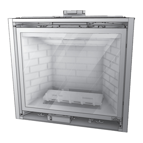
Page 9: Product Features
OVERVIEW 18. This appliance, when installed, must be electrically 20. Do not use if any part has been under water. Immediately grounded in accordance with local codes or in the call a qualified service technician to inspect and if absence of local codes, with the National Electrical needed replace any part of the control system and any Code, ANSI/NFPA 70, or the Canadian Electrical Code, gas control which as been under water. -
Page 10: Part Overview
OVERVIEW Gas Pressures Gas Specifications & Orifice Size Natural Propane (LP) Max. Input Min. Input Orifice Fuel BTU/h BTU/h Size Inlet Minimum 5.0" w.c. 12.0" w.c. Nat. 27,000 14,000 Inlet Maximum 10.5" w.c. 14.0" w.c. Natural Gas LP Gas 27,000 13,000 Manifold Pressure 3.8"... -
Page 11: Installation
INSTALLATION VENTING Rear Vent Application There are outlets for both top and rear venting. The unused vent exit must have the cover plates in place, IMPORTANT and the cover plates must be removed from the exit according to the instructions below to be used. When removing and refitting the plates be sure the associated gaskets are undamaged and refitted as required. - Page 12 INSTALLATION STEP 7 STEP 10 Attach the firebox exhaust cover to the firebox inside top Attach the intake inner draft hood to the firebox back using using the previously removed six (6) #10AX1/2 HX screws. the previously removed six (6) #10A X 1/2 HX screws. STEP 11 STEP 8 Attach the draft hood collar to the intake chamber using the...
-
Page 13: Approved Vent Systems
INSTALLATION Approved Vent Systems 46DVA-VC – Low Profile Cap Vertical DuraVent (DirectVent Pro) 46 DVA-VCH – Hi Wind Cap Vertical 46 DVA-HC – Square High Wind Cap Horizontal VDV-VCH04 – Round High Wind Cap Vertical Olympia Chimney (Ventis) VDV-VCH4 – Round Cap Vertical VDV-HC04 –... -
Page 14: Framing
INSTALLATION FRAMING The top stand-offs provide the minimum clearance to the header. Use only non-combustible material in this area for the entire width of the appliance. DO NOT use wood, sheet-rock, etcetera, in this zone. Top stand-off brackets must be formed and attached prior to positioning into framed opening. - Page 15 INSTALLATION Apply a generous amount of high temperature sealant to the around IMPORTANT the flue outlet. TYPICAL HORIZONTAL INSTALLATION TYPICAL HORIZONTAL INSTALLATION TOP VENT REAR VENT 1” 1” (25mm) (25mm) 15 ” 15 ” (403mm)* (403mm)* ¼ ¼ ” ” (920mm) (920mm) TYPICAL VERTICAL INSTALLATION...
-
Page 16: Floor Support And Protection
INSTALLATION Floor Support And Protection FIRE HAZARD: Do NOT install directly on carpeting, vinyl, or any other combustible material other than wood. • If installed directly on carpeting, tile, or other combustible material other than wood flooring, this appliance shall be installed on a metal or wood panel extending the full width and depth of the appliance. -
Page 17: Horizontal Terminations
INSTALLATION Horizontal Terminations Horizontal vent sections require 1/4 in (6 mm) rise for every 12 in (305 mm) of travel. IMPORTANT Measure from floor level of the appliance to the center of where the vent pipe will penetrate the wall. Elbows listed with approved vent systems will vary in vertical length. -
Page 18: Mantel And Finishing Requirements
INSTALLATION Depending on facing material, the lower half of the mounting bracket can be adjusted forward or backward ½ in (13 mm) as needed. Option 1 Option 2 Attach two (2) mounting brackets to each side of the unit. 1/2” (13mm) Clearance Stand-Off Flange Nailing Flange... -
Page 19: Gas Line Connection
INSTALLATION GAS LINE CONNECTION Gas Conversion (sold separately) The conversion shall be carried out in accordance with the requirements of the provincial authorities IMPORTANT having jurisdiction and in accordance with the requirements of the ANSI Z223.1 installation code. This appliance is manufactured for use with natural gas. Follow the instructions included with the conversion kit if converting to LP gas. -
Page 20: Termination Locations
INSTALLATION TERMINATION LOCATIONS Vertical Vent Cap Termination This appliance must not share or be connected to a chimney flue serving a separate solid-fuel burning appliance. LOWEST DISCHARGE OPENING APPROVED CAP MINIMUM 12” (.30m) APPROVED VENT PIPE ROOF PITCH = x/12 H - MINIMUM HEIGHT FROM ROOF TO LOWEST DISCHARGE OPENING Vertical Vent Cap Clearance... -
Page 21: Minimum Termination Clearances
INSTALLATION Minimum Termination Clearances AREA WHERE TERMINAL IS NOT PERMITTED Vent Cap Locations Canadian installations US installations Clearance above grade, veranda, porch, deck, or balcony 12 in (30 cm) 12 in (30 cm) Clearance to window or door that may be opened 12 in (30 cm) 9 in (23 cm) Clearance to permanently closed window (recommended to prevent condensation... -
Page 22: Top Vent (Vertical Only)
INSTALLATION TOP VENT (VERTICAL ONLY) Improper vent installation may cause the burner flames to lift or “ghost.” Perform a visual check on flame appearance after restrictor adjustment to ensure proper performance. Restrictor Adjustment Adjust the restrictor to achieve the desired flame appearance on any top venting configuration with 6 ft (1.83 m) of vertical pipe or more. -
Page 23: Top Venting
INSTALLATION TOP VENTING IMPORTANT Horizontal vent sections require ¼ in (6 mm) rise for every 12 in (305 mm) of travel. Vertical Terminations TOP VENTING DIAGRAM (VERTICAL & HORIZONTAL TERMINATIONS) (A) Stand-o Brackets NG/LPG - Minimum / Maximum Vertical Terminations 90°... -
Page 24: Rear Venting
INSTALLATION REAR VENTING IMPORTANT Horizontal vent sections require ¼ in (6 mm) rise for every 12 in (305 mm) of travel. Natural Gas Installations REAR VENTING DIAGRAM (VERTICAL & HORIZONTAL TERMINATIONS) Horizontal Terminations (A) Stand-o Brackets 90° Elbow Termination Cap NG - Minimum / Maximum Horizontal Venting NG - 6”... -
Page 25: Lp Gas Installations
INSTALLATION LP Gas Installations Horizontal vent sections require ¼ in (6 mm) rise for every 12 in (305 mm) of travel. IMPORTANT Horizontal Terminations REAR VENTING DIAGRAM (VERTICAL & HORIZONTAL TERMINATIONS) LPG - Minimum / Maximum Horizontal Venting (A) S tand-o Brackets (E) Horizontal Vent Heat Shield (not applicable) (B) S tand-o Heat Shields... -
Page 26: Log And Liner Installation
INSTALLATION LOG AND LINER INSTALLATION Do not place logs directly over burner port holes. Improper log placement may affect flame appearance and cause excessive soot to build upon the logs and glass. • If converting to LP (propane) gas, complete the conversion before installing the log set. Follow the conversion instructions included with the kit. -
Page 27: Install Glass Frame Assembly
INSTALLATION Pull the spring-loaded latches out and down to release the bottom of the glass assembly. Lift the glass assembly up and off of the (2) tabs located at the top of the firebox. Install Glass Frame Assembly Align the slots on top of the glass assembly over the tabs at the top of the firebox while lowering the bottom of the glass assembly into position. -
Page 28: Safety Barrier Information
INSTALLATION SAFETY BARRIER INFORMATION A barrier designed to reduce the risk of burns from the hot viewing glass is provided with this appliance and shall be installed for the protection of children and other at-risk individuals. If the barrier becomes damaged, the barrier shall be replaced with the manufacturer’s barrier for this appliance. - Page 29 INSTALLATION Wiring Schematics...
-
Page 30: Replacement Parts And Service
It is important to clean the flame sensor rod using emery cloth if flame rectification problems are encountered after use for a few months. Environmental factors beyond the control of Acadia can cause flame rectification concerns. How To Access Components The descriptions below show where the main components are located and how to access them for service. -
Page 31: Valve Assembly
INSTALLATION Valve Assembly Shutter Cable Tube Shutter Cable Bulk Head Pilot Top MTG Brkt Shutter Adjustment Sleeve Gas Pilot Pilot MTG Box Weldment Burner Orifice Shutter Adj. Burner Mount Plate Bottom Assembly Valve Assembly Shutter Adj. Mount Top Assembly Burner Accent Light Control Module Blower... -
Page 32: Homeowner Operation Installation Checklist
HOMEOWNER OPERATION INSTALLATION CHECKLIST All items on the checklist must be completed. Co-axial vent rigid pipe, wall vent cap or roof vent cap is installed by an approved service person in accordance with instructions. All joints are secured, "twist-locked" and leak-proof. 1000°F sealant is used on the inner pipe joints of all DuraVent pipe sections. -
Page 33: Remote Control Functions
HOMEOWNER OPERATION Within 7 seconds, press the “ON” button on the remote control. The appliance will beep to indicate that the remote control’s command is accepted and sets to the code of that controller. Your system is now synchronized. Sync Switch Master Switch Remote Control Functions You will hear a beep once every time a remote-... -
Page 34: Icon Details
HOMEOWNER OPERATION Automatic Safety Restart This system will execute an automatic turn off command within (24) hours of a continued pilot flame ignition. This allows the system to verify correct safety functions. After the turn off sequence is completed, the ignition module will re-execute the latest command. -
Page 35: Ipi And Cpi Modes
HOMEOWNER OPERATION Fan Speed Control: The fan speed can be adjusted through 6 speeds and off. To activate this function, press the Mode button until it displays the fan icon. Use the up/down arrow button to turn on, off, or adjust the fan speed. -
Page 36: Frequently Asked Questions
When requesting service, you will be asked to provide the model number, serial number, and manufacture date to your authorized dealer. This information will expedite the warranty verification process. This is an example of your listing label: Model / Modéle: AH3024FP SERIAL NO. / de série... -
Page 37: What Happens When First Lit
Adhesives, glue, wall substrate, wall finish material, paints, and polishes are common materials that if used incorrectly will cause odor issues. Acadia is not responsible for any odor issues caused by materials used. -
Page 38: How Do I Clean The Glass
HOMEOWNER OPERATION Check condition of glass door gasket, the gasket must seal tightly over firebox, Inspect gasket along top and sides of glass. If gasket at corners of glass are bulging outward or if gasket bulb along top edge or sides are discolored to a white color appearance through the whole thickness of the gasket bulb, then replace the gasket. -
Page 39: What Should I Do If Sooting Occurs
HOMEOWNER OPERATION instructions. Be sure all items in lighting and installation checklists are completed. Periodic visual check of pilot flames is required. Pilot flame must overlap flame sensor and burner ignition ports always. Especially for LP gas applications, always verify visible pilot flame length is at least 1” long. Periodic visual check of the burner flame is required. -
Page 40: Adjustment
HOMEOWNER OPERATION Turn off remote and wait 2 seconds. Turn on remote and wait 2 seconds. Turn off remote. This should clear the lockout mode. Turn on the remote and start the appliance. Ensure the master switch is in the “ON” position. -
Page 41: Burner Flame Adjustments
HOMEOWNER OPERATION Light burner. Check manometer reading. Turn burner and pilot off. Disconnect manometer hose and tighten the manifold (OUT) pressure tap by turning screw clockwise. Screw should be snug. Do not over tighten. Attach the manometer to the manifold pressure tap (B) to verify it is completely sealed. The manometer should read no pressure when pilot and burner are on. -
Page 42: Troubleshooting
HOMEOWNER OPERATION Factory Set Venturi Openings Fuel Air Shutter Opening Natural Gas Closed LP Gas 1/8” (3 mm) Open Air Shutter Controls TROUBLESHOOTING Before proceeding with the steps in the following troubleshooting guide, • Verify proper 120VAC power supply to the control module. •... - Page 43 HOMEOWNER OPERATION ON/OFF rocker switch in OFF position Gas supply turned off Check Check for multiple shut-offs in the supply line. Gas supply turned off Verify gas supply is turned on. Consult with plumber or gas supplier. Low gas supply Check LP (propane) tank.
-
Page 44: Burner And Pilot System
HOMEOWNER OPERATION The appliance area must be kept clear and free from combustible materials, gasoline and other flammable vapors and liquids. Burner And Pilot System The burner assembly may be removed for easier access to the control compartment. Performed by: Qualified Service Person Frequency: Annually Action: •... -
Page 45: Glass Assembly
Inspect the glass for cracks, scratches, and nicks. • Verify the glass assembly is properly intact and not damaged. • Replace the glass and the assembly as necessary. • Only Acadia Hearth will supply the replacement of glass assembly as a complete unit. - Page 46 NOTES...
- Page 47 NOTES...
Need help?
Do you have a question about the AH3024FP and is the answer not in the manual?
Questions and answers