
Related Manuals for SATO S84NX

Summary of Contents for SATO S84NX
- Page 1 Service Manual S84NX S86NX S84NX Left-Hand Type S86NX Right-Hand Type 1 Introduction 2 Operation Checking and 4 Replacement Performing Configuration Printer Adjustments 5 Options 6 Troubleshooting...
- Page 2 Limitation of Liability • SATO Corporation and its subsidiaries in Japan, the U.S. and other countries make no representations or warranties of any kind regarding this material, including, but not limited to, implied warranties of merchantability and fi tness for a particular purpose. SATO...
-
Page 3: Table Of Contents
2.3.4 WiFi Ex-Setting ................... 27 2.3.5 Reset ....................30 2.3.6 Maintenance ..................31 2.3.7 Position Check ..................32 2.3.8 Factory Off set ..................33 2.3.9 Factory Pitch ..................34 2. 4 Checking and Updating the Firmware ........35 S84NX/S86NX Service Manual... - Page 4 3. 4 Final Check ..................52 3.4.1 Checking Test Print with Factory Settings .......... 52 3.4.2 Checking the Customer’s Layout ............52 3.4.3 Checking Barcode Scan ..............52 3.4.4 Checking SOS Connection ..............53 3.4.5 Returning to the Original State ............53 S84NX/S86NX Service Manual...
- Page 5 4.7.2 Replacing the Timing Belt of Ribbon Motors ........108 4.7.3 Replacing the Timing Belt of Ribbon Unwind Mechanism ....110 4. 8 PCBs and Electrical Parts ............113 4.8.1 Replacing the Operator Panel (KB) PCB .......... 113 S84NX/S86NX Service Manual...
- Page 6 5. 2 Installing the RFID Kit ..............119 6 Troubleshooting ..............128 6. 1 About Error Message ..............128 6. 2 Error Code List ................129 6. 3 Error List ..................131 6. 4 Status Icon List ................143 7 Reference ................147 S84NX/S86NX Service Manual...
-
Page 7: Introduction
This service manual gives all the information necessary for you to adjust and repair the S84NX/S86NX. This service manual is written only for SATO authorized service personnel. The information in this manual is confi dential to general users. For basic specifi cation, installation, operation and confi gurations of the printer, refer to the operator manual of the S84NX/S86NX. -
Page 8: Parts Identifi Cation For The Product
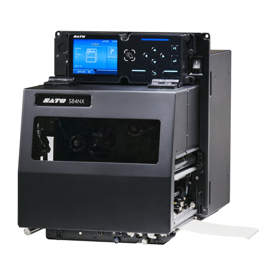
1. 3 Parts Identifi cation for the Product 1.3.1 Front View (1) Operator panel (2) Top cover Power (I/O) switch * Press this switch to power on (I) or power off (O) the product. (4) Media discharge outlet (5) USB connector (Type A) S84NX/S86NX Service Manual... -
Page 9: Rear View
> Usage of the RS-232C interface can be selected in the [Tools] [Barcode Checker] > [Test] [Interface] menu. (5) LAN connector (6) USB connector (Type A) (7) USB connector (Type B) (8) EXT connector (External signal interface) S84NX/S86NX Service Manual... -
Page 10: Internal View
Print head * Consumables (11) Creates an image directly on the media or by using a ribbon. Clean the print head regularly. (12) Feed roller * Consumables (13) Pressure roller * Consumables (14) Platen roller * Consumables S84NX/S86NX Service Manual... -
Page 11: Operator Panel View
Back button * Returns to the previous screen. (8) Left soft button * The functions change depending on the screen. The functions of the buttons are indicated on the bottom of the screen (9) Right soft button S84NX/S86NX Service Manual... -
Page 12: Internal View With Rear Cover Opened
CONT PCB board * The CONT PCB is the primary brain-center for all activities of the product. Gearbox * The stepper motor, timing belt and gears in the gearbox provide the main rotation motion for precise print positioning. S84NX/S86NX Service Manual... -
Page 13: Operation And Confi Guration
2.3.1 Logging in Service Menu 2.3.2 Details of the Service Menu 2.3.3 RFID 2.3.4 WiFi Ex-Setting 2.3.5 Reset 2.3.6 Maintenance 2.3.7 Position Check 2.3.8 Factory Off set 2.3.9 Factory Pitch 2. 4 Checking and Updating the Firmware S84NX/S86NX Service Manual... -
Page 14: About [Settings] Menu
Display the printer information and help videos. [Shortcut] Directly access frequently used settings. You can fi nd the [Service] menu in the [Tools] menu. However, users cannot access the [Service] menu without password. This menu is only for SATO authorized service personnel use. S84NX/S86NX Service Manual... -
Page 15: About [Tools] Menu
Save various information about the product in a text fi le to the USB memory. Support Info * Available only if you have installed the USB memory. Logging Function Enable, save, or delete the log information. Startup Guide Enable or disable the startup guide. S84NX/S86NX Service Manual... -
Page 16: Test Print
Place the label on the printer. > > > > Select [Settings] [Tools] [Test Print] [Factory] ] (right select button). After printing multiple labels, select [ ] (right select button) to stop the printing. Media feed direction S84NX/S86NX Service Manual... -
Page 17: Hex-Dump
Copy the selected log fi le to the USB memory. hexdump/ Note The data obtained by the hex dump (enabled) operation is stored. buff / Remove Delete the log fi les of the printer. hexdump/ buff / Print Print the selected log fi les. hexdump/ S84NX/S86NX Service Manual... -
Page 18: Reset
Initialize to the status of factory shipment. Factory Reset (–Interface) Initialize to the status after factory shipment except for [Interface]. Interface Initialize the setting values set in [Interface] main menu. Printing Initialize the setting values set in [Printing] main menu. S84NX/S86NX Service Manual... -
Page 19: Certifi Cates
Wi-Fi Client format. • pfx and .p12 for client certifi cates in PKCS #12 format. Wi-Fi Private Key • prv and .key for private keys in PEM/PKCS#8 format. EAP-FAST PAC File • pac for PAC fi les. S84NX/S86NX Service Manual... -
Page 20: Clone
Copy the printer settings and data, including network information (with Incl. LAN/Wi-Fi/IP the IP address), to the USB memory. This is useful when carrying over the settings of the printer to be replaced to a new printer. S84NX/S86NX Service Manual... -
Page 21: Startup Guide
To save the setting, select [ (right select button) once again. Time Set the current time in 24-hour format and select [ ] (right select button). To save the setting, select [ (right select button) once again. S84NX/S86NX Service Manual... - Page 22 ] (Enter key) End video ] (Right select button) Selection whether to show the startup guide at the next startup. Does not show the startup guide. ] (Right select button) Shows the startup guide. ] (Left select button) S84NX/S86NX Service Manual...
-
Page 23: About [Service Mode]
You need to enter the password to access the [Service] menu. Since the serial number of the PCB is used as the password, the password is diff erent for each product. CAUTION The [Service] menu is only for SATO authorized service personnel use. Print the factory settings. Refer to 3.1.3 Checking Printing with Factory Settings Enter the characters with "+ service"... -
Page 24: Details Of The Service Menu
Check the off set position of the label and show the error. Factory Off set Correct the off set position. Factory Pitch Off set the print position in the vertical direction. Check Communication Confi gure the Check Communication settings. S84NX/S86NX Service Manual... -
Page 25: Rfid
Enable or disable the RFID mode. When RFID mode is set to Enabled, RFID menu is displayed on the Interface menu. The options are as follows: • Enabled: Enable the RFID mode. • Disabled: Disable the RFID mode. S84NX/S86NX Service Manual... - Page 26 • Enabled: Perform the inventory check of the RFID tag. The product checks the taken tag number before writing to the tag. An error occurs when the number is other than one. • Disabled: Do not perform the inventory check of the RFID tags. S84NX/S86NX Service Manual...
- Page 27 • Enabled: Perform the verifi cation by reading the data of the written tag. If not match, the product prints VERIFY TAG ERR on the label. • Disabled: Do not perform the verifi cation of the written tag. S84NX/S86NX Service Manual...
- Page 28 Setting TYPE 3 TYPE 4 Feed media Stop feed Feed media Print start Write Print end Print motion Print Done TYPE 1 (PREND) Motion TYPE 2 Setting TYPE 3 TYPE 4 Feed media Stop feed Feed media S84NX/S86NX Service Manual...
-
Page 29: Wifi Ex-Setting
Select the region (frequency band) from the list. NOTE • Do not set to a region other than where the product is to be used. • The setting will be eff ective after you power on the product again. S84NX/S86NX Service Manual... - Page 30 AP is out of range or powered off . Supplicant Timeout Set a period of time for the EAP authentication timeout. Shows only if you have installed the optional wireless LAN. The options are as follows: • 5 sec • 30 sec S84NX/S86NX Service Manual...
- Page 31 • 60 sec AP scan Interval Set the interval for scanning access points. Shows only if you have installed the optional wireless LAN. The options are as follows: • 15 sec • 30 sec • 60 sec S84NX/S86NX Service Manual...
-
Page 32: Reset
Printing Initialize the setting values set in [Printing] main menu. Counters Head Initialize the head counte. Belt (Gear Box) Initialize the Belt (Gear Box) counte. Belt (Ribbon) Initialize the Belt (Ribbon) counte. Dispenser Initialize the Dispenser counte. S84NX/S86NX Service Manual... -
Page 33: Maintenance
(Default: Disabled) Disabled: Cannot change the USB serial number. USB Serial Enabled: Can change the USB serial number. To change the USB serial number, check the “Change USB Serial” in > > > Offl ine [Settings] [Interface] [USB]. S84NX/S86NX Service Manual... -
Page 34: Position Check
Set the allowable off set range in the media feed direction. Setting range: –60 to 60 dots (Default: 0 dots) Adjustment of “–” value (–60 dots) No adjustment (0 dots) Adjustment of “+” value Media feed (+60 dots) direction S84NX/S86NX Service Manual... -
Page 35: Factory Off Set
• The actual off set position is the sum of the off set value set here and the off set value set for print position, in Service menu. • When you change the off set value in the Service menu, the off set value set at factory shipment also changes. S84NX/S86NX Service Manual... -
Page 36: Factory Pitch
• The actual off set of the print position in the vertical direction is the sum of the off set value and the print position off set value set in Service menu. • When you change the value in the Service menu, the value set at factory shipment also changes. S84NX/S86NX Service Manual... -
Page 37: Checking And Updating The Firmware
Insert the USB memory into the USB connector (Type A). Power on the printer. Display the version to be updated. Select [ ] (right select button) to start updating. When the update is complete, the printer restarts automatically. S84NX/S86NX Service Manual... -
Page 38: Checking And Performing Printer Adjustments
3.3.1 Checking for Cover Open and Head Open Errors 3.3.2 Checking the Ribbon End Function 3.3.3 Checking and Adjusting the I-mark Sensor and Gap Sensor 3.3.4 Printing Quality 3.3.5 Meandering 3.3.6 Checking and Adjusting the Print Position 3.3.7 Checking the Stop Position S84NX/S86NX Service Manual... - Page 39 Back to top 3 Checking and Performing Printer Adjustments 3. 4 Final Check 3.4.1 Checking Test Print with Factory Settings 3.4.2 Checking the Customer’s Layout 3.4.3 Checking Barcode Scan 3.4.4 Checking SOS Connection 3.4.5 Returning to the Original State S84NX/S86NX Service Manual...
-
Page 40: Checking Before Starting Work
Check the user’s printer usage environment, label placing conditions, etc. Is the label placed in the proper position? Is there any excessive load on the routed wirings? Is there any problem with the label expiration date? Is the genuine label used? S84NX/S86NX Service Manual... -
Page 41: Checking Printing With Factory Settings
Place the label on the printer. > > > > Select [Settings] [Tools] [Test Print] [Factory] ] (right select button). After printing multiple labels, select [ ] (right select button) to stop the printing. Media feed direction S84NX/S86NX Service Manual... - Page 42 0.5 V or less HIGH High – Low 1.0 V Refer to 3.3.3 Checking and Adjusting the I-mark Sensor and Gap Sensor CAUTION After completion of the above check, print various setting information so that you can check it later. S84NX/S86NX Service Manual...
-
Page 43: Disabling The Sos Connection
2 min When performing inspections and repairs, notifi cation information is sent, so disable the SOS mode. > > > > Select [Settings] [Interface] [Network] [Services] [Online services]. Check that the SOS mode is set to Disabled. S84NX/S86NX Service Manual... -
Page 44: Checking And Cleaning
Pressure Roller Print Head (Thermal Head) Roller and Feed Sensor Cover *1 *1 Feed Sensor Cover Remove the cover and clean the inner parts as well. Label Guide Ribbon Roller Shaft Frame Feed Roller Pitch Sensor S84NX/S86NX Service Manual... -
Page 45: Checking And Cleaning The Exterior
CAUTION Before cleaning the PCB, make sure to power off the printer. Next, unplug the AC power cord. Is the connector loose? Is the screw loose? Is the cable caught? Is the gear broken or worn out? S84NX/S86NX Service Manual... -
Page 46: Checks And Adjustments
If no error occurs, replace the sensor. Refer to 4.5.5 Replacing the Top Cover Sensor Turn the head lock lever clockwise to unlock the print head. If no error occurs, replace the sensor. Refer to 4.5.4 Replacing the Head Open Sensor S84NX/S86NX Service Manual... -
Page 47: Checking The Ribbon End Function
Press the Back button on the operator panel to change the printer to offl ine mode. Select [ ] (right select button) and check that the buzzer sounds and the error message is displayed. If no error occurs, replace the sensor. Refer to 4.5.3 Replacing the Ribbon End Sensor S84NX/S86NX Service Manual... -
Page 48: Checking And Adjusting The I-Mark Sensor And Gap Sensor
Gap Sensor Y Auto-calibration > > > Select [Printing] [Advanced] [Calibrate] > [Auto-calibration] [Gap+I-Mark]. Remove the labels from the liner and place the liner so that the I-mark does not cover the sensor window. Sensor Windows S84NX/S86NX Service Manual... - Page 49 Receive level. With the screen as it is, set the media so that the label part is on the gap sensor. [Tips] For the sensor position, refer to step 2 of “Auto-calibration”. S84NX/S86NX Service Manual...
- Page 50 Check that the sensor level is less than 0.5 V. Adjustment Adjust the sensor level by changing the Send Gap Level. If you cannot set the sensor level to less than 0.5 V, change the Receive Gap Level. S84NX/S86NX Service Manual...
- Page 51 Adjust the sensor level by changing the Send Gap Level and Receive Gap Level. > Select [Calibrate] [I-Mark Slice Level]. You can set the slice level arbitrarily. Note When the slice level is 0, the slice level is automatically set. S84NX/S86NX Service Manual...
-
Page 52: Printing Quality
If the print quality is not uniform and hard to correct, lower the print darkness, and then check the test print results again. Is printing shrunk Pay attention to the ruled lines. If the ruled lines are missing, check the drive part as it may be the cause. S84NX/S86NX Service Manual... -
Page 53: Meandering
When you have adjusted the sensor levels, be sure to check the stop position. Check that the stop position on the 1st and 3rd labels is stable. No print skips occurs. If the problem persists, perform sensor adjustment again and recheck the roller, etc. S84NX/S86NX Service Manual... -
Page 54: Final Check
Ask the customer to print out with actual data, and make sure that there is no problem with the layout. 3.4.3 Checking Barcode Scan 1 min When the customer’s layout includes barcodes, QR codes, etc., perform readout checks to make sure that a scanner can read them correctly. S84NX/S86NX Service Manual... -
Page 55: Checking Sos Connection
On demand...Read an error code. Real time...Check that there is no problem with the communication state. 3.4.5 Returning to the Original State 3 min Check that the printer confi guration is the same as that before starting the service work. S84NX/S86NX Service Manual... -
Page 56: Replacement
4.4.3 Replacing the Pressure Roller 4.4.4 Replacing the Media Feed Roller 4.4.5 Replacing the Torque Limiter for Ribbon Spindle 4.4.6 Replacing the BF Spring for Ribbon Supply Spindle 4.4.7 Replacing the Ribbon Roller 4.4.8 Replacing the Gearbox S84NX/S86NX Service Manual... - Page 57 4.7.1 Replacing the Timing Belt of Gearbox 4.7.2 Replacing the Timing Belt of Ribbon Motors 4.7.3 Replacing the Timing Belt of Ribbon Unwind Mechanism 4. 8 PCBs and Electrical Parts 4.8.1 Replacing the Operator Panel (KB) PCB S84NX/S86NX Service Manual...
-
Page 58: Notes On Replacing Parts
0 When assembling parts, do not pinch cables or wires. 0 Replace tapes and stickers with new ones depending on their condition. 0 There are several kinds of screws. Be sure to use the correct type of screws when assembling. S84NX/S86NX Service Manual... -
Page 59: Removing The Housing Cover
(S2) at the rear. Open the interface side of the rear housing cover ( ), then open the other side that has a fl ap on the rear housing cover ( Flap S84NX/S86NX Service Manual... - Page 60 Check the connector. All cable connectors must POWER SUPPLY UNIT: A, B, C, D be connected. CONT PCB: E, F, G, H, I, J, K, L, M, N, O LH type RH type S84NX/S86NX Service Manual...
- Page 61 Head cable *S86NX only Head cable Check FG cable position. Red dotted line a, d, f Omega lock: Check omega lock, Cable tie position. b, c, e Cable tie: Check each cable route. For details, refer to “3. Wiring route”. S84NX/S86NX Service Manual...
- Page 62 Head cable *S86NX only Head cable Check FG cable position. Red dotted line a, d, f Omega lock: Check omega lock, Cable tie position. b, c, e Cable tie: Check each cable route. For details, refer to “3. Wiring route”. S84NX/S86NX Service Manual...
- Page 63 ) is placed between the saddle-1 and saddle-2. • Make sure that the Ribbon motor RW cable (A) and Ribbon motor UW cable (B) run through the saddle-2. LH type RH type Saddle-2 Saddle-2 Saddle-1 Saddle-1 S84NX/S86NX Service Manual...
- Page 64 • Pay attention to the location of the cable tie on the AC line cable (D). • Make sure that the Inlet cable (E) and AC line cable (D) are fixed with the cable tie (e). LH type Cable tie RH type Cable tie S84NX/S86NX Service Manual...
- Page 65 Make sure that the cable tie attached to the head power cable is on the POWER UNIT side. LH type RH type Head power cable POWER CABLE ASSY Head power cable POWER CABLE ASSY Cable tie Cable tie S84NX/S86NX Service Manual...
- Page 66 RH type • Make sure that the POWER CABLE ASSY is fixed with the ferrite core ( • Make sure that thePOWER CABLE ASSY run through the saddle. LH type RH type Saddle Saddle S84NX/S86NX Service Manual...
- Page 67 • Make sure that the stepping motor cable is fixed to the saddle-2 with the cable tie (b). LH type Saddle-2 Cable tie Cable tie CLAMP 20 mm RH type 20 mm Cable tie Saddle-2 S84NX/S86NX Service Manual...
- Page 68 • Make sure that the head cable is fixed with the ferrite core ( LH type Saddle • Make sure that the saddle is located near the cable tie of the head cable. Cable tie Saddle Saddle Cable tie RH type CLAMP Saddle S84NX/S86NX Service Manual...
- Page 69 Omega lock mounting position Install using the position of the hole in the plate as a guide. RH type Omega lock mounting position Install using the position of the hole in the plate as a guide. S84NX/S86NX Service Manual...
-
Page 70: Removing The Front Housing Cover
Remove three screws (S7) and remove the USB unit ( Notes on assembling • Attach the USB unit so that the SENSOR SW BR cable ( ) is not pinched. Disconnect the SENSOR SW BR cable connector ( S84NX/S86NX Service Manual... - Page 71 Remove four screws (S15) attached to the front housing cover ( Hold and support the front housing cover while removing the screws. From here, assembling procedure Assemble the parts in the reverse order of the disassembly procedure. S84NX/S86NX Service Manual...
-
Page 72: Printing Section
Be careful not to touch it, to avoid being burned. • Touching the edge of the print head with your bare hand could cause injury. Loosen the HEAD CABLE COVER thumb screw ) and remove the HEAD CABLE COVER. S84NX/S86NX Service Manual... - Page 73 ) from the print head backwards, install the print head ( Notes on assembling • Align the print head and press the print head upward until it is latched. Reverse the procedure from step 3. Reverse the procedure from step 3. S84NX/S86NX Service Manual...
-
Page 74: Paper Transfer Section
• Touching the edge of the print head with your bare hand could cause injury. Loosen the screw (S3) until the bearing clamp ( ) is released. Do not remove the screw. Notes on assembling • While aligning the bearing clamp with the platen roller, tighten the screw. S84NX/S86NX Service Manual... - Page 75 Back to top 4 Replacement Remove the platen roller ( Remove the ball bearing ( From here, assembling procedure Assemble the parts in the reverse order of the disassembly procedure. S84NX/S86NX Service Manual...
-
Page 76: Replacing The Pressure Roller Plate
) up to release the pressure roller plate ( Turn the pressure roller knob ( ) counterclockwise to remove the pressure roller plate ( From here, assembling procedure Assemble the parts in the reverse order of the disassembly procedure. S84NX/S86NX Service Manual... -
Page 77: Replacing The Pressure Roller
) up to release the pressure roller plate ( Loosen the screw (S3) until the bearing clamp ( ) is released. Do not remove the screw. Notes on assembling • While aligning the bearing clamp with the pressure roller, tighten the screw. S84NX/S86NX Service Manual... - Page 78 While pushing the pressure roller release tab ( ) upward, remove the pressure roller ( Remove the ball bearing ( From here, assembling procedure Assemble the parts in the reverse order of the disassembly procedure. S84NX/S86NX Service Manual...
-
Page 79: Replacing The Media Feed Roller
The feed roller and media sensor assembly will flip open. Loosen the screw until the bearing clamp is released. (S3) Do not remove the screw. Notes on assembling • While aligning the bearing clamp with the media feed roller, tighten the screw. S84NX/S86NX Service Manual... - Page 80 Back to top 4 Replacement Remove the Media feed roller ( Remove the ball bearing ( From here, assembling procedure Assemble the parts in the reverse order of the disassembly procedure. S84NX/S86NX Service Manual...
-
Page 81: Replacing The Torque Limiter For Ribbon Spindle
On the other side of the product (rear side), remove the screw (S3) attached to the other end of ribbon supply spindle ( Hold the thin shaft (a) while removing the screw (S3). NOTE • In this case, be careful not to cut your hand on the corners of the BOSS SPRING (c). S84NX/S86NX Service Manual... - Page 82 • For S86NX, the ribbon spindles have an extended outer boss as shown. Before removing the front boss , remove the outer boss and a C-snap ring From here, assembling procedure Assemble the parts in the reverse order of the disassembly procedure. S84NX/S86NX Service Manual...
-
Page 83: Replacing The Bf Spring For Ribbon Supply Spindle
On the other side of the product (rear side), remove the screw (S3) attached to the other end of ribbon supply spindle ( Hold the thin shaft (a) while removing the screw (S3). NOTE • In this case, be careful not to cut your hand on the corners of the BOSS SPRING (c). S84NX/S86NX Service Manual... - Page 84 ). The lower straight end of the BF spring ( is on the left side of the projection (RED dotted line) as shown. Then pull the top straight end and hook onto the right side of the projection. S84NX/S86NX Service Manual...
- Page 85 ) such that the two straight ends of the BF spring ( ) are pointing downward and the metal projection is in between them. Striaght ends of the BF spring Metal projection From here, assembling procedure Perform the assembly with the reverse procedure from step 8. S84NX/S86NX Service Manual...
-
Page 86: Replacing The Ribbon Roller
Remove the print head from the product. Refer to 4.4.5 Remove the ribbon rewind spindle. Step 2 Step 1 Step 3 Step 5 Step 4 On the front of the product, remove two screws (S3) and the belt cover ( S84NX/S86NX Service Manual... - Page 87 ( Loosen three screws and remove the UW ribbon roller and RW ribbon roller. UW Ribbon Roller RW Ribbon Roller From here, assembling procedure Assemble the parts in the reverse order of the disassembly procedure. S84NX/S86NX Service Manual...
-
Page 88: Replacing The Gearbox
4.2.1 Opening the Rear Housing Cover Disconnect the motor cable ( Remove three screws (S15) and remove the gearbox ( Fastening the ground wire together From here, assembling procedure Assemble the parts in the reverse order of the disassembly procedure. S84NX/S86NX Service Manual... -
Page 89: Sensors
To access the lower screw, you need to pull the feed lock latch ( ) to unlock the media sensor assembly. Withdraw the media sensor assembly ( Be careful not to pull the attached sensor cable ( S84NX/S86NX Service Manual... - Page 90 ) attached to the media sensor cover ( Release two hooks ( ) and remove the TOP MEDIA SENSOR PCB ( Disconnect one connector. Connector From here, assembling procedure Assemble the parts in the reverse order of the disassembly procedure. S84NX/S86NX Service Manual...
- Page 91 Turn the sensor bracket ( ) to change its direction. Be careful not to pull the attached sensor cable ( █ BOTTOM MEDIA SENSOR PCB Remove two screws (S18) and remove the BOTTOM MEDIA SENSOR PCB ( Disconnect one connector. Connector S84NX/S86NX Service Manual...
- Page 92 Then remove the screw and remove the MEDIA SENSOR ASSEMBLY OPEN SENSOR ( Disconnect one connector. Then remove the screw (S27) and remove the MEDIA SENSOR ASSEMBLY OPEN SENSOR ( Screw Connector From here, assembling procedure Perform the assembly with the reverse procedure from step 3. S84NX/S86NX Service Manual...
-
Page 93: Replacing The Ribbon Sensor
Open the rear housing covers of the product. Refer to 4.2.1 Opening the Rear Housing Cover Disconnect the ribbon feed sensor cable ( On the front of the product, remove two screws (S3) and the belt cover ( S84NX/S86NX Service Manual... - Page 94 Back to top 4 Replacement Remove the screw and replace the ribbon sensor ( Screw From here, assembling procedure Assemble the parts in the reverse order of the disassembly procedure. S84NX/S86NX Service Manual...
-
Page 95: Replacing The Ribbon End Sensor
Remove the print head from the product. Refer to 4.4.5 Remove the ribbon rewind spindle. Step 2 Step 1 Step 3 Step 5 Step 4 On the front of the product, remove two screws (S3) and the belt cover ( S84NX/S86NX Service Manual... - Page 96 Then carefully remove the frame of the print head assembly ( Remove the screw and replace the ribbon end sensor ( Screw From here, assembling procedure Assemble the parts in the reverse order of the disassembly procedure. S84NX/S86NX Service Manual...
-
Page 97: Replacing The Head Open Sensor
Remove the screw, disconnect the sensor cable and replace the head open sensor Notes on assembling • Pass the sensor cable through the clamp. Screw CLAMP From here, assembling procedure Assemble the parts in the reverse order of the disassembly procedure. S84NX/S86NX Service Manual... -
Page 98: Replacing The Top Cover Sensor
Remove three screws (S7) and remove the USB unit ( Notes on assembling • Attach the USB unit so that the SENSOR SW BR cable ( ) is not pinched. Disconnect the SENSOR SW BR cable connector ( S84NX/S86NX Service Manual... - Page 99 Remove two screws (S10) and remove the Top Cover Sensor ( Remove two screws (S9) and remove the Top Cover Sensor ( From here, assembling procedure Assemble the parts in the reverse order of the disassembly procedure. S84NX/S86NX Service Manual...
-
Page 100: Pcbs And Electrical Parts
) of the product. NOTE • Open the top cover fully to prevent accidental drop of the cover. Open the rear housing covers of the product. Refer to 4.2.1 Opening the Rear Housing Cover Disconnect the USB cable connector ( S84NX/S86NX Service Manual... - Page 101 Remove two screws (S2) and remove the USB PCB ( Notes on assembling • Attach the USB unit so that the SENSOR SW BR cable ( ) is not pinched. From here, assembling procedure Assemble the parts in the reverse order of the disassembly procedure. S84NX/S86NX Service Manual...
-
Page 102: Replacing The Main (Cont) Pcb
G: HEAD, connects to the print head assembly. H: USBH, connects to the USB PCB. I: FEED, connect to the gearbox motor. J: RIBBON_RW, connects to the RW ribbon motor. K: RIBBON_UW, connects to the UW ribbon motor. Remove two screws (S2). S84NX/S86NX Service Manual... - Page 103 • Tighten the screws in the order of circled numbers. • Be careful not to forget to attach the ground wire. Fastening the ground wire together From here, assembling procedure Assemble the parts in the reverse order of the disassembly procedure. S84NX/S86NX Service Manual...
-
Page 104: Replacing The Power Supply Unit
(CONT) PCB. D: AC line, connects to the power switch. Remove four screws (S4) and remove the power supply unit. From here, assembling procedure Assemble the parts in the reverse order of the disassembly procedure. S84NX/S86NX Service Manual... -
Page 105: Replacing The Fan Motor
) to release the fan cable ( Disconnect the fan cable ( Remove two screws (S5) and remove the fan motor ( From here, assembling procedure Assemble the parts in the reverse order of the disassembly procedure. S84NX/S86NX Service Manual... -
Page 106: Replacing The Coin Battery
Open the rear housing covers of the product. Refer to 4.2.1 Opening the Rear Housing Cover Replace the coin battery ( ) with a new one. From here, assembling procedure Assemble the parts in the reverse order of the disassembly procedure. S84NX/S86NX Service Manual... -
Page 107: Replacing The Timing Belt
) of the tension link. NOTE • Do not remove the screws. On the gear side of the gearbox, remove the e-ring ( ) using a slotted screwdriver. Then remove the gear ( ) and timing belt ( S84NX/S86NX Service Manual... - Page 108 Then remove the gear ( ) and timing belt ( Loosen the screw ( ) of the tension bracket A. NOTE • Do not remove the screws. On the gear side of the gearbox, remove the timing belt ( S84NX/S86NX Service Manual...
- Page 109 ) of the tension bracket B and the screw ( ) of the tension link. NOTE Do not remove the screws. The tension of the timing belts will be adjusted automatically by the spring pressure. Tighten the screws that were loosened. S84NX/S86NX Service Manual...
-
Page 110: Replacing The Timing Belt Of Ribbon Motors
(S15) easily, insert a thin shaft into a hole through the ribbon rewind spindle ( ) as shown on the picture. Then hold the ribbon rewind spindle ( ) while removing the screw (S15). Remove the bearing ( ) and pulley bracket ( S84NX/S86NX Service Manual... - Page 111 Ribbon rewind motor Ribbon supply motor The standard position of the motor screws. Setting the motor to the standard position provides a standard tension applied on the timing belt. S84NX/S86NX Service Manual...
-
Page 112: Replacing The Timing Belt Of Ribbon Unwind Mechanism
Remove the gearbox from the product. Refer to 4.3.1 Remove the print head from the product. Step 2 Step 1 Step 3 Step 4 On the front of the product, remove two screws (S3) and the belt cover ( S84NX/S86NX Service Manual... - Page 113 (S14) using an Allen wrench. Then remove the screw (S13) and remove the head lock lever ( Remove three screws (S3) and remove the Side plate ( ) and UW Ribbon Roller ( Replace the timing belt ( S84NX/S86NX Service Manual...
- Page 114 Back to top 4 Replacement Notes on assembling • Check the route of the timing belt. From here, assembling procedure Assemble the parts in the reverse order of the disassembly procedure. S84NX/S86NX Service Manual...
-
Page 115: Pcbs And Electrical Parts
4.8.1 Replacing the Operator Panel (KB) PCB Open the rear housing covers of the product. Refer to 4.2.1 Opening the Rear Housing Cover Remove two screws (S24). While feeding the cables by hand, remove the KEYBOARD PANEL ASSY ( Disconnect two connectors. Connectors S84NX/S86NX Service Manual... - Page 116 Details of the KEYBOARD PANEL ASSY DESCRIPTION PANEL COVER S/A S84-86NX NFC CABLE SET-LF S26 ×4 BUTTON LED LENS PANEL BASE S26 ×4 From here, assembling procedure Assemble the parts in the reverse order of the disassembly procedure. S84NX/S86NX Service Manual...
-
Page 117: Installation Of Options
Back to top Installation of Options This chapter describes how to remove and install the options. 5. 1 Replacing the W-LAN Kit 5. 2 Installing the RFID Kit S84NX/S86NX Service Manual... -
Page 118: Replacing The W-Lan Kit
(S2) at the rear. Open the interface side of the rear housing cover ( ), then open the other side that has a fl ap on the rear housing cover ( Flap S84NX/S86NX Service Manual... - Page 119 Use tweezers, etc. to vertically connect or disconnect the coaxial cable connector. the coaxial cable connector. • • Applying force to one side of the connector only will Applying force to one side of the connector only will damage the connector. damage the connector. S84NX/S86NX Service Manual...
- Page 120 ) of the antenna sub with the convex part ( ) of the IF plate. From here, assembling procedure Assemble the parts in the reverse order of the disassembly procedure. Wi-Fi Settings Refer to 2.3.4 WiFi Ex-Setting S84NX/S86NX Service Manual...
-
Page 121: Installing The Rfid Kit
(S2) at the rear. Open the interface side of the rear housing cover ( ), then open the other side that has a fl ap on the rear housing cover ( Flap S84NX/S86NX Service Manual... - Page 122 ) and remove the HEAD CABLE COVER. Turn the head lock lever ( ) clockwise to unlock the print head. Remove the print head ( Refer to 4.4.8 Replacing the Print Head Unplug the connector in the order of a and b. S84NX/S86NX Service Manual...
- Page 123 On the rear of the product, remove three screws (S4). Then carefully remove the frame of the print head assembly ( Push the pressure roller release tab ( ) up to release the pressure roller plate ( S84NX/S86NX Service Manual...
- Page 124 Attach the UHF NORMAL ASSY ( ) while inserting its coaxial cable into the cable routing groove ( ) of the product. Tighten the UHF NORMAL ASSY using a screw attached to the UHF RFID Kit. Screw S84NX/S86NX Service Manual...
- Page 125 Close the pressure roller plate ( Install the print head assembly ( ) and fi x it using three screws (S4). Remove two screws and remove the head pwb cover ( TIPS The screws are reused. Screws S84NX/S86NX Service Manual...
- Page 126 • Make sure that the protruding part of the cable (c) is 4.0 to 5.0 mm from the end face of the print head. Pass the coaxial cable of the UHF FRONT ASSY through the print head assembly. Notes on assembling • Pass the coaxial cable between the two print head connectors. S84NX/S86NX Service Manual...
- Page 127 While pulling back the cables, insert the print head inside the print head assembly. Then, align its position and push it upward until it is latched. Place the cables in the print head assembly, pass the coaxial cable through the cable hole, and feed it to the rear of the product. S84NX/S86NX Service Manual...
- Page 128 5 Installation of Options Attach the HEAD CABLE COVER ( ) and belt cover ( The position of the WIRE SADDLE on the UHF RFID MODULE ASSY is diff erent between the LH and RH models. LH moel LH moel S84NX/S86NX Service Manual...
- Page 129 • The UHF RFID MODULE PCB has two connectors, ANT1 and ANT2, so connect each coaxial cable correctly. UHF FRONT ASSY UHF NORMAL ASSY (ANT1) (ANT2) Fix the UHF RFID MODULE ASSY ( ) using two screws attached to the UHF RFID Kit. Screws S84NX/S86NX Service Manual...
- Page 130 ) and fi x it using three screws (S15). Connect the connector. Fastening the ground wire together Connector Close the rear housing covers and fi x them using four screws. RFID Settings Refer to 2.3.3 RFID S84NX/S86NX Service Manual...
-
Page 131: Troubleshooting
Message The procedure to clear an error is displayed. LED Indicator Lights in red when an error occurs. When an error occurs, a long buzzer sounds once, or a short Error Buzzer Sound buzzer sounds three times. S84NX/S86NX Service Manual... - Page 132 Error Message 1020 (Calendar Error) Error Message 1021 (BCC Check Error) Error Message 1022 (Print Head Overheated) Error Message 1023 (NTP Error) Error Message 1024 (Head Density Changed) Error Message 1028 (GAP Not Found) Error Message 1029 (Cover Open) S84NX/S86NX Service Manual...
- Page 133 Error Message 1078 (Barcode Reading Error) Error Message 1079 (Barcode Reading Error) Error Message 1080 (Barcode Comparison Error) Error Message 1099 (Confi g Warning) Error Message 1136 (Label Sensor Cover Open) Error Message 1141 (Printing was aborted halfway) S84NX/S86NX Service Manual...
-
Page 134: Error List
To clear the display Press the left select button (OFFLINE) or LINE button. 1) RS-232C settings are incorrect. Causes 2) The RS-232C cable is not connected correctly. 1) Adjust the interface settings correctly. Countermeasures 2) Connect the RS-232C cable correctly. S84NX/S86NX Service Manual... - Page 135 1) Thermal head assembly isn’t closed. Causes 2) Sensor is dirty for detecting head open/close. 3) Failure of sensor for detecting head open/close. 1) Close the thermal head assembly. Countermeasures 2) Sensor is cleaned. 3) Exchange of sensor substrates. S84NX/S86NX Service Manual...
- Page 136 3) There is no ribbon. 4) The ribbon sensor is not operating correctly. 1) Load the ribbon. 2) Load the ribbon and the media correctly. Countermeasures 3) Load a new ribbon. 4) Clean and adjust carbon ribbon path. S84NX/S86NX Service Manual...
- Page 137 4) The USB memory is not formatted. 1) Connect the USB memory. 2) Make sure that the USB memory has suffi cient copy area. Countermeasures 3) Replace the USB memory. 4) Format the USB memory to FAT32 format. S84NX/S86NX Service Manual...
- Page 138 Printing position is out of printable area the printable area. The printing image is outside the printable Barcode image is out of printable area area. (Barcode only) Check the print data. Countermeasures If the problem persists, restart the printer. S84NX/S86NX Service Manual...
- Page 139 To clear the display Stop the operation of the product to let the temperature decrease. Causes The temperature of the product has exceeded its tolerance value. Countermeasures Stop the operation of the product to let the temperature decrease. S84NX/S86NX Service Manual...
- Page 140 4) The media sensor level is incorrect. 1) Load the media correctly. 2) Clean the media sensor. Countermeasures 3) Set the media sensor type which is compatible with the media you use. 4) Adjust the media sensor level. S84NX/S86NX Service Manual...
- Page 141 Light in red sound, (EAP Failure) 3 times Message Erroneous Wi-Fi settings. Adjust settings. To clear the display Change the Wi-Fi settings or press the left select button (OFFLINE). Causes EAP Authentication failure. Countermeasures Use the correct Wi-Fi settings. S84NX/S86NX Service Manual...
- Page 142 Long 1075 NFC Error Light in red sound, one time Message Contact customer service. To clear the display Press the left select button (OFFLINE). Causes The NFC module is not operating correctly. Countermeasures Replace the NFC module. S84NX/S86NX Service Manual...
- Page 143 • Press the right select button (CANCEL) to cancel the print job and change to Offl ine mode. Causes Could not read the barcode correctly. • Check the layout for printing. Countermeasures • Check the barcode checker position and its settings. S84NX/S86NX Service Manual...
- Page 144 The power was cut off in an inappropriate way, such as the power cord was Causes pulled out while the power was on. • Power off the product correctly. Countermeasures • Reset the product in the Settings menu. S84NX/S86NX Service Manual...
-
Page 145: Status Icon List
In dispense & print mode, printing was interrupted by a cancel operation or Causes error. Press the left select button (OFFLINE) or LINE button to switch to Offl ine Countermeasures mode, and then press the button to feed and eject the labels that have fi nished printing part way. S84NX/S86NX Service Manual... - Page 146 Not connected to the NTP time server. Wi-Fi is authenticated, but not connected. Wi-Fi is connected. Signal Level: 1 Wi-Fi is connected. Signal Level: 2 Wi-Fi is connected. Signal Level: 3 Wi-Fi is connected. Signal Level: 4 Wi-Fi Direct is not connected. S84NX/S86NX Service Manual...
- Page 147 Waiting for external input/output signal. Standard code is disabled. The On-Demand mode of the SOS (SATO Online Services) is enabled. The Real Time mode or the Light mode of the SOS is enabled. The product is connected to the SOS cloud.
- Page 148 Receive buff er is nearly full. Stop sending print data until the buff er is no longer nearly full. Defective print head is detected. Replace the print head. Incompatible print head is detected. Replace the print head. S84NX/S86NX Service Manual...
- Page 149 Icons notify you about cleaning the product and replacing parts at the set periods when [Notifi cations] is enabled. Icon Description Clean the print head or platen roller. Replace the print head. Replace the platen roller. Replace the belt(Gear Box). Replace the belt(Ribbon). S84NX/S86NX Service Manual...
-
Page 150: Reference
Reference This chapter describes the following: 1 Location of Sensors and Options 2 Checking the Power Supply Voltage Back to top S84NX/S86NX Service Manual... - Page 151 America: Standard/RH America: Opposite/LH Europe/Asia: LH Europe/Asia: RH Dispense stop position Print head Print head Media feed direction Gap sensor position I-mark sensor position 5.0 mm 5.0 mm 5.0 to 81.0 mm 5.0 to 81.0 mm Frame Frame S84NX/S86NX Service Manual...
- Page 152 Back to top Reference Printable Area S84NX Series LH S84NX Series RH America: Standard/RH America: Opposite/LH Europe/Asia: LH Europe/Asia: RH Media feed direction Frame Frame Base reference position for printing Base reference position for printing Print head Print head...
- Page 153 Back to top Reference 2 Checking the Power Supply Voltage Measurement Points C661:1.2V Q4-D:5VC TP94:2.5V TP7:3.3V J29-4(Black):GND PS1: EXT 5V J29-1(Yellow):24V J2-15(Black):GND J2-8(Red):5V TP18:3.3V S84NX/S86NX Service Manual...
Need help?
Do you have a question about the S84NX and is the answer not in the manual?
Questions and answers