Table of Contents
Advertisement
Quick Links
Advertisement
Table of Contents

Related Manuals for SATO S84NX

Summary of Contents for SATO S84NX
- Page 1 FX3-LX...
-
Page 2: Table Of Contents
Table of Contents Table of Contents Before You Start......................8 About This Manual..........................8 Safety Precautions..........................9 Copyrights............................14 Trademarks............................15 What You Can Do with This Product..............16 Features of the Product........................16 Various Ways to Output........................17 Outputting with General-purpose Software.................17 Outputting and Controlling with Dedicated Command..............18 Controlling the Product with External Signal................ - Page 3 Front View..........................72 Rear View..........................72 Media Dispensed View......................73 Top View..........................74 Installing the Product onto a Support Structure/Applicator............77 Powering On/Off the Product......................78 Connecting the Power Cord......................78 Powering On the Product......................79 Powering Off the Product......................81 Initial Setup (Startup Guide)......................83 Startup Guide Flow........................
- Page 4 [Imaging]..........................158 [Advanced]..........................161 [Interface] Menu.........................179 [Network]..........................179 [RS-232C]..........................219 [USB]............................ 222 [NFC]............................ 223 [Ignore CR/LF]........................223 [Ignore CAN/DLE].........................223 [External I/O]........................223 [RFID] (S84NX Only)......................228 [Applications] Menu........................238 [Protocol]..........................238 [Auto Switch Group]......................239 [SBPL]...........................241 [SZPL]...........................246 [SIPL]............................ 248 [STCL]...........................250 [SDPL]..........................250 [SEPL]...........................258 [AEP].............................258 [System] Menu...........................260...
- Page 5 Operations in Dispenser Mode....................327 Operations in Dispense & Print Mode..................335 Operations in Linerless Mode....................340 Operations for RFID Write (S84NX Only).................342 Operations When the Barcode Check Function Is Enabled............. 350 Adjusting the Base Reference Point....................351 About the Base Reference Point....................351 Adjusting the Print Position.......................
- Page 6 Replacing the Pressure Plate....................462 Replacing the Feed Roller......................466 Replacing the Fan Filter......................470 Operating the Notification Screen of the SOS (SATO Online Services) On-Demand Mode (SOS users only)............................471 SOS (SATO Online Services) Application (SOS users only)............473 When You Are in Trouble..................474 When an Error Message Appears....................
- Page 7 Media Size for Each Print Speed....................558 Usable Ribbon..........................559 Usable Fonts..........................560 Usable Barcodes..........................584 Support and Warranty....................586 SOS (SATO Online Services) (SOS users only)................586 Warranty for Consumables within the Product Warranty Period............587...
-
Page 8: Before You Start
Before You Start About This Manual Thank you for purchasing the SATO S84NX/S86NX (hereafter referred to as "the product"). This manual supplies basic information on how to operate the product. Read the manual carefully to understand each function of the product before operation. -
Page 9: Safety Precautions
Safety Precautions This topic describes how to use the product safely. Be sure to read the following information carefully before using the product. Pictographic Symbols This operator manual and the product labels use a variety of pictographic symbols. These symbols emphasize the safe and correct use of the product and to prevent injury to others and property damage. - Page 10 • If the product is dropped or breaks, immediately power it off, unplug the power cord from the outlet, and contact your SATO reseller or technical support. Using the product in one of these conditions could result in a fire or electric shock.
- Page 11 Do not operate with wet hands • Do not disassemble or modify the product. Doing so could result in a fire or electric shock. Ask your SATO reseller or technical support to conduct internal inspections, adjustments, and repairs.
- Page 12 • To replace the print head, follow the procedure in the Operator Manual. If the Operator Manual does not contain this procedure, avoid trying to replace it on your own terms, and contact your SATO reseller or technical support. •...
- Page 13 Cover • When not using the product for a long time, unplug the power cord from the outlet to maintain safety. When not using the product for a long time • When maintaining and cleaning the product, unplug the power cord from the outlet to maintain safety.
-
Page 14: Copyrights
Copyrights Copyrights Any unauthorized reproduction of the contents of this document, in part or whole, is strictly prohibited. © 2022 SATO Corporation. All rights reserved. -
Page 15: Trademarks
Trademarks • The following are registered trademarks of SATO Holdings Corporation and its subsidiaries in Japan, the U.S. and other countries. ◦ SATO ◦ Stylized SOS (SATO Online Services) • ® NiceLabel is a trademark or registered trademark of Euro Plus d.o.o. -
Page 16: What You Can Do With This Product
• Supports 31 languages for display and 47 languages for printing scalable fonts • SBPL (SATO Barcode Printer Language) supported as well as many other printer commands like SZPL • IPv6, SNMP, NTP, and other protocols supported in various communication interfaces •... -
Page 17: Various Ways To Output
Labels can be easily output by using software, such as the NiceLabel series. • NiceLabel series This software has multiple functions and is easy to operate so you can create and print labels with richly versatile layouts. • For details of the products, contact your SATO sales representative. -
Page 18: Outputting And Controlling With Dedicated Command
In addition, you can print characters, barcodes, and graphics in various styles by combining multiple SBPL commands. There are many functions for modifying the printed items, such as enlarging fonts, specifying a print direction, ruled line, and black and white reverse printing. For programming references, contact your SATO sales representative or technical support. -
Page 19: Controlling The Product With External Signal
Controlling the Product with External Signal By using the external signal (EXT) interface, you can connect the product to an external device and print. With the control signal, you can control print operations; such as monitoring the condition of the product, starting printing, and reprinting. -
Page 20: Outputting With Standalone (Aep) Applications
Outputting with Standalone (AEP) Applications Outputting with Standalone (AEP) Applications Labels can be printed by running standalone (AEP) applications within the product. • For details of the standalone applications, contact your SATO sales representative. -
Page 21: Outputting With Simple Standalone Application
1. Use label software, such as NiceLabel, Bartender, etc., to create a label format. • It is recommended to use SATO printer fonts instead of True Type fonts but it is not a requirement. Graphic images are also acceptable to use. - Page 22 Outputting with Simple Standalone Application 4. When the product is in Online mode, press the button on the operator panel to change to Offline mode. 5. Press the button to show the [Settings] menu. • Input the password if it is enabled. 6.
- Page 23 If some applications have already been loaded in this product, select [Simple Standalone] using the buttons, and then press the button. • The simple standalone application is pre-loaded into the product and cannot be removed. 8. Enable AEP mode by selecting the [Enable] menu and reboot the product to apply the settings.
- Page 24 Outputting with Simple Standalone Application 10. Select the format with the buttons, and then press the button or button. The screen shows a list of files without extensions which are stored on the USB memory. 11. If the format contains a variable, enter the variable with the on-screen keyboard or a USB scanner, keyboard or keypad connected to the product.
- Page 25 12. If the format contains a counter, enter the start value of the counter with the on- screen keyboard or a USB scanner, keyboard or keypad. 13. Enter the print quantity to start printing the label format. • Once printing has started, the USB memory can be removed. The USB memory will be required when starting the next print job.
-
Page 26: Basic Information
Bundled Accessories After unpacking the product, make sure that you have all the bundled accessories. If there are any missing items, contact the SATO reseller where you purchased the product. • User documents (Quick Guide, Safety Instructions, Global Warranty Program leaflet, Product Information Download, Declaration of Conformity) •... -
Page 27: Optional Devices
Available UHF RFID kit and write to the RFID tag. Cannot be installed after the product is purchased. Contact your SATO sales representative before purchasing the product. • For more details about the optional devices, contact your SATO sales representative. -
Page 28: Product Orientation
This product has two types of orientation, as shown below. The media feed direction varies depending on the type of orientation. • The illustrations in this manual are of the S84NX (Standard/Left-hand type), unless otherwise noted. • If you are using the Opposite/Right-hand type, then the illustrations in this manual will appear to be reversed. -
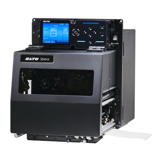
Page 29: Parts Identification
Parts Identification Parts Identification for the Product Front View (1) Operator panel (2) Display (3) Top cover (4) Power (I/O) switch Press this switch to power on (I) or power off (O) the product. (5) Media discharge outlet Rear View (1) Wireless LAN antenna (Optional) Connector for installation of optional wireless LAN antenna. - Page 30 • Be sure to perform a virus check on the USB memory before connecting it to the product. SATO Corporation shall not be held responsible for any product malfunctions caused by a virus spread via USB memory. (7) USB connector (Type B) To connect the product to the computer using the USB interface.
- Page 31 Also, other devices like a barcode checker, barcode scanner or keyboard can be connected. • Be sure to perform a virus check on the USB memory before connecting it to the product. SATO Corporation shall not be held responsible for any product malfunctions caused by a virus spread via USB memory. •...
- Page 32 Parts Identification for the Product (7) Media sensor adjustment knob Used to adjust the position of the media sensor. (8) Pressure plate (Consumables) (9) Ribbon rewind spindle (10) Head lock lever Used to release the print head assembly. (11) Ribbon roller (12) Print head (Consumables) Creates an image directly on the media or by using a ribbon.
-
Page 33: Parts Identification For The Operator Panel
Parts Identification for the Operator Panel (1) Display (2) NFC antenna location Arrow buttons Navigate the selection in the screen menu. (4) LED indicator LINE button Toggle between Online/Offline mode or playback/pause the video. Enter button Confirm the selected item or setting value. Back button Returns to the previous screen. - Page 34 Parts Identification for the Operator Panel Soft buttons The functions change depending on the screen. The functions of the buttons are indicated on the bottom of the screen. Example 1: In Offline mode left soft button: ONLINE, right soft button: FEED Example 2: The numerical value input screen of the Settings menu left soft button: Delete one character, right soft button: Save...
-
Page 35: Using The Operator Panel
Using the Operator Panel LED Indicator The LED indicator lights up or flashes to show the current status of the product. The product statuses which the LED indicator shows are as follows: LED Indicator Color/Status Description Blue/Lights on Online mode Lights off Power off or Offline mode Red/Lights on... -
Page 36: Operations In Online/Offline Mode
Operations in Online/Offline Mode Operations in Online/Offline Mode Online Mode In Online mode, you can execute the print job. In the default settings, the product powers on in Online mode. (1) Change to Offline mode. (2) Shows the [Shortcut] menu. You can change various settings during printing by registering them to the [Shortcut] menu in advance. - Page 37 After you complete or cancel the print job, you can show the Settings mode. (1) Cancel the print job. When there are no print jobs, the product changes to Online mode. (2) Change to Online mode. (3) Feed the media. (4) Shows the [Shortcut] menu when the print job is paused.
- Page 38 Operations in Online/Offline Mode (5) Product orientation Shows either LH/RH or STD/OPP, depending on the country/region in which the product was purchased. (6) Number of pages in the print job being processed When the [System] > [Show Total Count] menu in the Settings mode is enabled, the total number of pages printed from after the power was turned on is shown in parentheses.
-
Page 39: Status Icon
Status Icon The icons on the status bar of the display show the product's status. (1) Status bar Communication Interface Status Icon Description Network link is enabled but not connected. NFC is enabled but not connected. NFC is enabled and connected. Not connected to the NTP time server. - Page 40 Status Icon Icon Description Wi-Fi is connected. Signal Level: 1 Wi-Fi is connected. Signal Level: 2 Wi-Fi is connected. Signal Level: 3 Wi-Fi is connected. Signal Level: 4 Wi-Fi Direct is not connected. Wi-Fi Direct is connected. Signal Level: 1 Wi-Fi Direct is connected.
- Page 41 Product is connected to USB host. Waiting for external input/output signal. RFID mode is enabled. (S84NX only) RFID mode is enabled, but the system is defective. (S84NX only) Standard code is disabled. The On-Demand mode of the SOS (SATO Online Services) is enabled.
- Page 42 Status Icon Icon Description Time period set for periodic notification for On-Demand mode for SOS has been reached. Scan the QR code and send the information to the SOS cloud. IP address could not be acquired. Or a communication error has occurred. USB Memory Status Icon Description...
- Page 43 Print Job Status Icon Description Ribbon is near the end. The rest of the ribbon is decreased. Prepare a new ribbon. Label is near the end. The rest of the media is decreased. Prepare new media. Command error detected. Check the print data. Receive buffer is nearly full.
- Page 44 Status Icon Icon Description Replace the print head. Replace the platen roller. Replace the belt (Gear Box). Replace the belt (Ribbon).
-
Page 45: Operations When Errors Occur
Change to guidance video. • Change to the SOS error screen on which the QR code and phone number are displayed if the SOS (SATO Online Services) is enabled. • The available operations vary, depending on the situation. (1) Error Icon (2) Error number (3) Clear the error if allowed for the active error. -
Page 46: Adjusting The Print Settings During Printing
Adjusting the Print Settings During Printing Adjusting the Print Settings During Printing You can change various settings during printing by registering them to the [Shortcut] menu in advance. Follow the procedure below to adjust the setting items registered to the [Shortcut] menu during printing. - Page 47 • When [Printing] > [Advanced] > [Prioritize] menu has been set to [Commands] and the print settings have been specified by command, the changes made in the [Shortcut] menu will be applied only to the data already analyzed at that time. The settings specified by command will be applied to the rest of the data.
-
Page 48: Canceling The Print Job
Canceling the Print Job Canceling the Print Job Cancel the print job according to the following procedure. When the print job is canceled, the data stored in the receive buffer of the product is also deleted. 1. Press the button or button to change the product to Offline mode. - Page 49 When the printer language of the print data is SBPL, SDPL, or SZPL When the printer language of the print data is some other language The print job is canceled.
-
Page 50: Guidance Videos
Guidance Videos Guidance Videos The product contains guidance videos that are shown on the display for visual reference of the product's operations. -
Page 51: List Of The Guidance Videos
List of the Guidance Videos The product contains the guidance videos for visual reference of product operations. The onboard guidance videos are as follows: Guidance video Show video from Error screen Startup Guide [Information] Menu Media loading Possible Possible Possible Possible Ribbon loading Media replacement... -
Page 52: Playing The Guidance Video From The Error Screen
Playing the Guidance Video from the Error Screen Playing the Guidance Video from the Error Screen Play the guidance video from the error screen and resolve the error by following the procedure of the video. 1. On the error screen, press the button to play the guidance video. -
Page 53: Getting Access To The Guidance Video In Online Mode
Getting Access to the Guidance Video in Online Mode When in the Online mode, play the guidance video according to the following procedure. 1. Press the button or button in Online mode. The product changes to Offline mode. 2. Press the button. - Page 54 Getting Access to the Guidance Video in Online Mode 3. Select [Information] using the buttons. 4. Press the button. The item list appears. 5. Select [Help] using the buttons. 6. Press the button. The guidance video list appears.
- Page 55 7. Select the category of the video for playback using the buttons, and then press the button. 8. Select the video for playback using the buttons, and then press the button. The guidance video starts.
-
Page 56: Operating The Guidance Video
Operating the Guidance Video Operating the Guidance Video (1) Indication panel appears again when one of the buttons is pressed. (2) Stop the playback of the video and return to menu. (3) Playback the video from the start. (4) Playback or pause the video. (5) Rewind the video. -
Page 57: Settings Mode
Settings Mode In the Settings mode, you can set the product's various settings. The topics here explain how to operate the Settings mode. -
Page 58: Settings Mode Menus
Settings Mode Menus Settings Mode Menus There are the following main menus in the Settings mode and each menu contains many layers of submenus. Frequently used settings are also listed in the [Shortcut] menu so that you can directly access them. Menu Description Shortcut Menu... -
Page 59: Changing To The Settings Mode
Changing to the Settings Mode The Settings mode appears when no print jobs remain in the product. Change the product to the Settings mode according to the following procedure: 1. Press the button or button in Online mode. The product changes to Offline mode. 2. - Page 60 Changing to the Settings Mode The product changes to Settings mode. • To exit the Settings mode, press the button.
-
Page 61: Logging In To/Logging Out Of The Settings Mode
Logging In to/Logging Out of the Settings Mode The Settings mode logs in and logs out by the following procedure, if the password is enabled. • If the password is enabled, input the password after entering the Settings mode. When logged in to the Settings mode, [LOG OUT] appears on the bottom left of the screen. •... -
Page 62: Item Selection
Item Selection Item Selection Select an item in Settings mode according to the following procedure: 1. Select menu using the buttons. 2. Press the button. The item list appears. 3. Select an item using the buttons. 4. Press the button. If the selected item is a setting item, the setting screen appears. - Page 63 Similarly, select an item using the buttons. Press the button to return to the previous screen. (1) There are more items in the next layer. (2) Return to the previous screen.
-
Page 64: Setting Value Input Or Selection
Setting Value Input or Selection Setting Value Input or Selection This topic describes the character and number input on the setting screen and how to select an item from the list. • You can also input characters and numbers from a USB keyboard by connecting it to the product. - Page 65 • Numeric Input (1) Text box (2) Selection area (3) Delete the number displayed to the left of the cursor in the text box. (4) Select the number for input using the arrow buttons. The selected number will be highlighted in the selection area.
- Page 66 Setting Value Input or Selection • Selection from the Box (1) Change the value in the selection box using the buttons. (2) Selection box (3) Perform the function as shown on the screen. (4) Return to the previous screen. (5) Select an item using the buttons.
-
Page 67: Customizing The [Shortcut] Menu
Customizing the [Shortcut] Menu By registering setting items to the [Shortcut] menu, you can directly access registered settings and you can change some of the items during printing. Registering Items to the [Shortcut] Menu You can register items to the [Shortcut] menu according to the following procedure: 1. -
Page 68: Unregistering Items From The [Shortcut] Menu
Unregistering Items from the [Shortcut] Menu 3. Press the button on the confirmation screen. Registering the item to the [Shortcut] menu is complete, and the icon turns to the icon. Unregistering Items from the [Shortcut] Menu You can unregister items from the [Shortcut] menu according to the following procedure: 1. - Page 69 3. Press the button on the confirmation screen. The item is removed from the [Shortcut] menu. • You can also unregister items on the setting screen relative to each item.
-
Page 70: Product Memory And Usb Memory
Get the support information • Be sure to perform a virus check on the USB memory before connecting it to the product. SATO Corporation shall not be held responsible for any product malfunctions caused by a virus spread via USB memory. •... -
Page 71: Getting Started
Getting Started Installation • When you want to take the product to countries other than where you purchased it, contact your SATO reseller. -
Page 72: Installation Space
Rear View Installation Space Front View The dimensions of the front view of the product are as follows: • The encircled positions show the 5 holes for installing the product in the support structure. • The figure above is the Standard/Left-hand type. If you are using the Opposite/Right-hand type, then the direction is the opposite. -
Page 73: Media Dispensed View
Make sure that there is sufficient space around the product so that the top cover can be fully opened when operating or cleaning the product, or replacing consumables. The dimensions of the media dispensed view of the product are as follows: S84NX • The figure above is the Standard/Left-hand type. If you are using the Opposite/Right-hand type,... -
Page 74: Top View
Top View S86NX • The figure above is the Standard/Left-hand type. If you are using the Opposite/Right-hand type, then the direction is the opposite. Top View Make sure that there is sufficient space on the rear side of the product so that the rear housing cover can be fully opened during maintenance. - Page 75 S84NX • The figure above is the Standard/Left-hand type. If you are using the Opposite/Right-hand type, then the direction is the opposite.
- Page 76 Top View S86NX • The figure above is the Standard/Left-hand type. If you are using the Opposite/Right-hand type, then the direction is the opposite.
-
Page 77: Installing The Product Onto A Support Structure/Applicator
Installing the Product onto a Support Structure/Applicator To operate correctly, the product must be installed on a support structure or applicator. The product has five mounting holes on the center frame for installation on a support structure. Put five bolts through the five holes on the center frame to install the product on the support structure. •... -
Page 78: Powering On/Off The Product
Make sure that the AC voltage of your region is in the range of AC 100 - 240 V, 50 - 60 Hz. If your local voltage is not in the stated range, contact your SATO reseller or technical support. -
Page 79: Powering On The Product
Powering On the Product • Do not power on or off the product, connect or disconnect the power cord while your hands are wet. Doing so could cause an electric shock. 1. Press the power (I/O) switch to "I" position. "Online"... - Page 80 Powering On the Product • You can power on/off the product from the main power source, from which the product takes its power, because it is equipped with a start on AC function. To turn the power on and off from the main power source, leave the power (I/O) switch of the product in the "I"...
-
Page 81: Powering Off The Product
Powering Off the Product • Do not power on or off the product, connect or disconnect the power cord while your hands are wet. Doing so could cause an electric shock. • Do not power off the product during operation, such as when printing or updating. Doing so could cause a malfunction of the product. - Page 82 Powering Off the Product • You can power on/off the product from the main power source, from which the product takes its power, because it is equipped with a start on AC function. To turn the power on and off from the main power source, leave the power (I/O) switch of the product in the "I"...
-
Page 83: Initial Setup (Startup Guide)
Initial Setup (Startup Guide) The topics here explain how to complete the startup guide that appears when you power on the product for the first time after purchase. -
Page 84: Startup Guide Flow
Startup Guide Flow Startup Guide Flow The startup guide is a function to help you through the initial product settings (language selection, date and time settings, loading the ribbon and media, etc.). You can cancel the startup guide and perform the configuration later from the menu. •... - Page 85 4. Select the city to set for the time zone. 5. Select the current year, month, and date. When the confirmation screen appears, press the button to confirm the settings. 6. Select the current time. • The time is set in the 24-hour format. When the confirmation screen appears, press the button to confirm the settings.
- Page 86 Startup Guide Flow 7. Select the print method to use. (Available only for the combined direct thermal/thermal transfer model.) [Use Ribbon] Prints using a ribbon. [Direct Thermal] Prints using direct thermal media. 8. Load the ribbon while checking the video. a.
- Page 87 9. Select the sensor type for detecting the media. [Gap] Select when using the media of Gap type. Use the transmissive sensor. [I-Mark] Select when using the media of I-mark type. Use the reflective sensor. 10. Load the media while checking the video. a.
- Page 88 Startup Guide Flow 11. To show the startup guide the next time the product is started, press the button. To not show it, press the button. • You can set whether to open the startup guide the next time you start up the product in [Startup Guide] in the [Tools] menu.
-
Page 89: Startup Guide Cancelation
Startup Guide Cancelation You can cancel the startup guide at any time. 1. Press the button while configuring the startup guide. The screen to confirm whether or not to show the startup guide again appears. 2. Select whether or not to show the startup guide during the next startup using the buttons, and press the button to confirm. -
Page 90: Manually Setting The Print Mode
Manually Setting the Print Mode Manually Setting the Print Mode You can change the print mode of the product according to its usage. The product has the following print modes: [Continuous] Prints the specified number of media. The media remains in position for printing at all times. [Dispenser] Peels the liner from the printed label as the label is fed to the media discharge outlet. - Page 91 2. Press the button. The product changes to Settings mode. • Input the password if it is enabled. 3. Select [Printing] using the buttons. 4. Press the button. The item list appears.
- Page 92 7. Select the print mode using the buttons. • (S84NX only) Do not select Linerless Mode to use RFID tags on an RFID model. If you set Linerless Mode, you cannot use RFID tags. 8. Press the button to confirm.
-
Page 93: Connecting The Product To A Computer
Connecting the Product to a Computer This section explains how to connect the product to a computer, and how to install the printer driver and the All-In-One Tool. -
Page 94: Procedure For Connecting The Product To A Computer
Procedure for Connecting the Product to a Computer Procedure for Connecting the Product to a Computer The product supports various interfaces and can be connected to a computer in an optimum way for your environment. When you have installed the printer driver to the computer, the data created with the computer (documents and illustrations) can be printed to a label through easy operations. -
Page 95: Connecting Interfaces
Connecting Interfaces Available Interfaces The product supports the following interfaces. • A product connected with multiple interface cables can continue to operate when receiving data. However, you cannot receive data from more than one interface at a time. Normally, do not use multiple interfaces at a time. •... -
Page 96: Usb Interface Connection (Standard)
USB Interface Connection (Standard) How to connect the host computer and the applicator to the product • Do not connect or disconnect the interface cables (or use a switch box) while power is supplied to either the product or computer. This may cause damage to the interface circuitry in the product or computer and is not covered by warranty. -
Page 97: Lan Interface Connection (Standard)
The USB interface is selected after connecting the USB cable to the computer and the product, and powering on the product while the computer is turned on. • If the product is powered on without installing the printer driver, Windows' Plug & Play runs. -
Page 98: Rs-232C Interface Connection (Standard)
RS-232C Interface Connection (Standard) • If it does not communicate well, shift the Android device to the front, back, left and right, and then hold it up again. • For the operation of the NFC for the Android device, refer to the user manual for the Android device. -
Page 99: Wireless Lan Interface Connection (Optional)
• To use the RS-232C interface to connect with the computer, the product's [Tools] > [Barcode Checker] > [Test] > [Interface] menu must be set to [RS-232C]. • The interface settings of the computer can be confirmed by the following. In the Device Manager, right-click [Ports (COM &... - Page 100 Wireless LAN Interface Connection (Optional) The communication condition settings must be configured according to your network environment. Set the IP address of the product. The IP address of the product can be set through the product's [Interface] menu or the All-In-One Tool. •...
-
Page 101: Configuring The Interface Settings
Configuring the Interface Settings Interface Setting Methods Configure the interface settings of the product according to the communication conditions of the connected network and computer. You can set the interface settings of the product doing either of the following. • Set from the Settings mode of the product •... - Page 102 Configuring the Interface Settings from the Interface Menu of the Product 2. Press the button. The product changes to Settings mode. • Input the password if it is enabled. 3. Select [Interface] using the buttons. 4. Press the button. The item list appears.
-
Page 103: Configuring The Interface Settings Using The All-In-One Tool
Sets to ignore CR/LF codes. [Ignore CAN/DLE] Sets to ignore CAN/DLE codes. [External I/O] Sets the external signal (EXT). [RFID] (S84NX only) Sets the RFID. Appears only for the RFID model. 6. Press the button. The settings items of the selected interface appear. - Page 104 Configuring the Interface Settings Using the All-In-One Tool Download the All-In-One Tool and All-In-One Tool Manual from your local SATO website https:// www.sato-global.com/drivers/redirect.html, and install the software to a computer. For the compatible OS, refer to the "System Requirements" section of the All-In-One Tool Manual.
-
Page 105: Installing The Printer Driver
Installing the Printer Driver The printer driver is software that can send data created on the computer (documents and illustrations) to the product and print it to a label. Download and use the printer driver from your local SATO website https://www.sato-global.com/ drivers/redirect.html. -
Page 106: All-In-One Tool Features
All-In-One Tool Features When you add the product to the All-In-One Tool, you can easily set and manage the product. • For details of the All-In-One Tool, download and read the All-In-One Tool Manual from your local SATO website. https://www.sato-global.com/drivers/redirect.html... -
Page 107: Loading Media And Ribbon
Loading Media and Ribbon Media, Ribbon and Print Methods The product is available in two models, the direct thermal model and the combined direct thermal/ thermal transfer model. The media or ribbon to be used varies depending on the print method. Thermal transfer (combined direct thermal/thermal transfer model only) Prints using a ribbon. -
Page 108: Loading Media
Usable Media Loading Media Usable Media The product can print on a media roll. The product uses media sensors to detect I-marks or gaps on the media in order to precisely print the content. I-mark label Gap label I-mark journal paper/ linerless label (1) Media feed direction... -
Page 109: Adjusting The Position Of The Media Sensor
The position of the Gap sensor is adjustable. You can adjust the Gap sensor position in the following range. S84NX: 5 to 66 mm (0.2" to 2.6") measured from the product's center frame. S86NX: 5 to 81 mm (0.2" to 3.2") measured from the product's center frame. -
Page 110: Winding Direction Of The Media
Winding Direction of the Media Winding Direction of the Media The media either winds face-out or face-in. Load the media with the print side facing up. Face-out Face-in The print side faces the outer side of the media. The print side faces the inner side of the media. (1) Print side... -
Page 111: Precautions For Loading The Media
Precautions for Loading the Media Use our specified supply products for the product, for optimum print quality. • The print head and its surroundings are hot after printing. Be careful not to get burned. • Touching the edge of the print head with your bare hand could cause injury. •... -
Page 112: Loading Media With Dispenser
Loading Media with Dispenser Loading Media with Dispenser The below topic describes the procedure to dispense the label and eject the liner out of the product. • The routing path of the media is shown in the below picture. Label Liner 1. - Page 113 2. Turn the head lock lever (2) clockwise to unlock the print head. 3. Pull the feed lock latch (3) to unlock the feed roller and media sensor assembly. The feed roller and media sensor assembly (4) will flip open. 4.
- Page 114 Loading Media with Dispenser 5. Pass the media between the media shaft (6), below the feed roller and media sensor assembly (4), and the print head assembly (7) and extend it out the discharge outlet (8). Make sure that the end of the media extends out the discharge outlet. 6.
- Page 115 7. Pull the label out from the discharge outlet and remove about 30 cm (11.8") of labels (9) from the liner (10). 8. Push the tab (11) up to release the pressure plate (12). 9. Pass the liner (10) through the gap of the pressure plate (12).
- Page 116 Loading Media with Dispenser 10. Turn the head lock lever (2) counterclockwise to lock the print head , and then press the feed roller and media sensor assembly (4) down until the feed lock latch (3) is locked 11. Pull the liner (10) lightly so that the media does not sag.
- Page 117 12. Push the center of the pressure plate (12) to latch it in place. 13. Close the top cover. • When closing the top cover, be careful not to pinch your fingers. 14. Press the button (FEED) in Offline mode to feed the media. 15.
-
Page 118: Loading Media Without Using Dispenser
Loading Media without Using Dispenser Loading Media without Using Dispenser The below topic describes the procedure to just load the media without using the dispenser. • The routing path of the media is shown in the below picture. 1. Open the top cover (1). •... - Page 119 2. Turn the head lock lever (2) clockwise to unlock the print head. 3. Pull the feed lock latch (3) to unlock the feed roller and media sensor assembly. The feed roller and media sensor assembly (4) will flip open. 4.
- Page 120 Loading Media without Using Dispenser 5. Pass the media between the media shaft (6), below the feed roller and media sensor assembly (4), and the print head assembly (7) and extend it out the discharge outlet (8). Make sure that the end of the media extends out the discharge outlet. 6.
- Page 121 7. Turn the head lock lever (2) counterclockwise to lock the print head , and then press the feed roller and media sensor assembly (4) down until the feed lock latch (3) is locked 8. Close the top cover. • When closing the top cover, be careful not to pinch your fingers.
-
Page 122: Loading Ribbon (Thermal Transfer Only)
Loading Ribbon (Thermal Transfer Only) Loading Ribbon (Thermal Transfer Only) You need to load the ribbon when printing using thermal transfer. The topics here explain how to load and replace the ribbon. -
Page 123: Checking The Ink Side Of The Ribbon
Checking the Ink Side of the Ribbon There are two winding directions for the ribbon. Face-out means the ink is on the outer side and Face- in means the ink is on the inner side. The product supports both winding directions. You can examine the ink side of the ribbon using the following procedure. - Page 124 Checking the Ink Side of the Ribbon ◦ The ink is coated on the inner side. (Face-in ribbon)
-
Page 125: Loading The Ribbon
Touching the edge of the print head with your bare hand could cause injury. • Use genuine SATO media and ribbons for the product, for optimum print quality. • The routing path of the ribbon is shown in the below picture. - Page 126 Loading the Ribbon • Open the top cover fully to prevent accidental drop of the cover. 2. Turn the head lock lever (2) clockwise to unlock the print head.
- Page 127 3. Load an empty ribbon core (3) onto the ribbon rewind spindle (4). Insert the core all the way in. If there is any ribbon on the ribbon rewind spindle, remove it from the spindle before installing new ribbon. 4. Load the ribbon (5) onto the ribbon supply spindle (6). While taking note of the winding direction, insert the ribbon all the way in.
- Page 128 Loading the Ribbon 5. From the ribbon supply spindle (6), pass the ribbon below the print head (7) and to the ribbon rewind spindle (4). Face-in ribbon Face-out ribbon 6. Wind the ribbon clockwise around the empty ribbon core and attach the free end of the ribbon to the ribbon core with adhesive tape (8).
- Page 129 7. Turn the ribbon rewind spindle (4) clockwise for several rounds to wind the ribbon while removing the slack from the ribbon. 8. If the media is already loaded, turn the head lock lever (2) counterclockwise to lock the print head. 9.
-
Page 130: Replacing The Ribbon
Replacing the Ribbon Replacing the Ribbon 1. Open the top cover (1). • Open the top cover fully to prevent accidental drop of the cover. 2. Turn the head lock lever (2) clockwise to unlock the print head. - Page 131 3. Pull to remove the used ribbon from the ribbon rewind spindle (3). 4. Pull to remove the empty core from the ribbon supply spindle (4). 5. Load an empty ribbon core (5) onto the ribbon rewind spindle (3). Insert the core all the way in.
- Page 132 Replacing the Ribbon 6. Load the ribbon (6) onto the ribbon supply spindle (4). While taking note of the winding direction, insert the ribbon all the way in. Make sure that the ink side of the ribbon is facing down when passing it below the print head. 7.
- Page 133 8. Wind the ribbon clockwise around the empty ribbon core and attach the free end of the ribbon to the ribbon core with adhesive tape (8). 9. Turn the ribbon rewind spindle (3) clockwise for several rounds to wind the ribbon while removing the slack from the ribbon.
- Page 134 Replacing the Ribbon • When closing the top cover, be careful not to pinch your fingers. 12. Press the button (FEED) in Offline mode to feed the media. 13. Press the button (ONLINE) or button to change to Online mode.
-
Page 135: Settings To Match The Media
Settings to Match the Media Print Method (Combined Direct Thermal/Thermal Transfer Model Only) For the combined direct thermal/thermal transfer model, you can select from two types of print methods. Thermal transfer Prints using a ribbon. Direct thermal Prints using direct thermal media. •... - Page 136 Print Method (Combined Direct Thermal/Thermal Transfer Model Only) 2. Press the button. The product changes to Settings mode. • Input the password if it is enabled. 3. Select [Printing] using the buttons. 4. Press the button. The item list appears.
- Page 137 5. Select [Printing Mode] using the buttons. 6. Press the button. The [Printing Mode] screen appears. 7. Select the print method using the buttons. [Use Ribbon] Prints using a ribbon. [Direct Thermal] Prints using direct thermal media. 8. Press the button to confirm.
-
Page 138: Media Sensor Type
Media Sensor Type Media Sensor Type The product adjusts the print position precisely by detecting I-marks or gaps on the media (label) using media sensors. The I-marks or gaps on each type of media are as follows: I-mark label Gap label I-mark journal paper/ linerless label (1) Media feed direction... - Page 139 2. Press the button. The product changes to Settings mode. • Input the password if it is enabled. 3. Select [Printing] using the buttons. 4. Press the button. The item list appears.
- Page 140 Media Sensor Type 5. Select [Sensor Type] using the buttons. 6. Press the button. The [Sensor Type] screen appears. 7. Select the sensor type to detect the print position using the buttons. [None] Disables the media sensor. [Gap] Select when using gap type media. Use the transmissive type sensor. [I-Mark] Select when using I-mark type media.
-
Page 141: When To Replace Media And Ribbon
When to Replace Media and Ribbon Checking the Remaining Amount of Media and Ribbon You can check the remaining amount of media and ribbon according to the following procedure. • Checking through the window on the front side of the product You can visually check the remaining amount of ribbon in the product through the window on the front of the product (1). -
Page 142: Conditions That Trigger Paper End
Conditions That Trigger Paper End Conditions That Trigger Paper End The conditions that trigger paper end vary depending on the operation of the product, and the sensor type selected. If I-mark (reflective type) or Gap (transmissive type) is specified as the paper end sensor, then the paper end is detected according to the following conditions. - Page 143 (2) Paper end detection level (fixed) (3) Gap sensor waveform *1 The paper end distance can be set in the [Printing] > [Advanced] > [Paper End] > [Paper End Distance] menu. Conditions That Trigger Paper End in the Printing Operation 1.
- Page 144 Conditions That Trigger Paper End Amount of media remaining = distance between print head position and paper end sensor -paper end distance (1) Print head position (2) Distance between the print head position and paper end sensor (3) Paper end sensor (4) Paper end distance (5) Amount of media remaining When the Amount of Printing Remaining Is More Than the Amount of Media Remaining...
- Page 145 • When the Amount of Printing Remaining Is Less Than the Amount of Media Remaining If the amount of printing remaining is less than the amount of media remaining, the product will finish the print job and a paper end error will occur. (1) Print head position (2) Paper end sensor (3) Paper end distance...
- Page 146 Conditions That Trigger Paper End operation after an error, eject the partially printed label to start printing. Reprinting starts by printing the interrupted print item on the next label. (1) Print head position (2) Paper end sensor (3) Paper end distance (4) Amount of media remaining (5) Amount of printing remaining (6) Amount to feed until dispenser stop position...
-
Page 147: Conditions That Trigger Label Near End
Conditions That Trigger Label Near End Label near end is detected by the label near end sensor on the applicator. The label near end condition is received as an external signal from the applicator and a warning icon appears in the status bar on the upper part of the screen. •... -
Page 148: Conditions That Trigger Ribbon End (Thermal Transfer Only)
Conditions That Trigger Ribbon End (Thermal Transfer Only) Conditions That Trigger Ribbon End (Thermal Transfer Only) Ribbon end error is detected by the ribbon sensor in the ribbon supply spindle. Ribbon end error occurs when the product detects that the ribbon in the ribbon supply spindle has not moved (rolled) more than 32 mm (1.26") after feeding the media. -
Page 149: Conditions That Trigger Ribbon Near End (Thermal Transfer Only)
Conditions That Trigger Ribbon Near End (Thermal Transfer Only) Ribbon near end is detected by the ribbon sensor in the ribbon supply spindle. Ribbon near end occurs when the amount of ribbon remaining is approximately less than 15 meters (49.2 feet) (ribbon diameter: approximately 36 mm (1.42")). -
Page 150: Various Settings Of The Product
The Product's [Settings] Menu Various Settings of the Product The Product's [Settings] Menu The following categories of menus are available for the [Settings] menu of the product. Click the icon to jump to the description of each menu item. • The [Language] menu appears if you enable it by going to the [System] >... -
Page 151: [Shortcut] Menu
[Shortcut] Menu By registering setting items to the [Shortcut] menu, you can directly access registered settings and you can change some of the items during printing. -
Page 152: [Printing] Menu
Set the length of the media. The setting range varies depending on the print resolution of the product. The setting range of the label length is as follows: Resolution S84NX S86NX 203 dpi 1 to 20000 dots 1 to 20000 dots (1 dot = 0.125 mm... -
Page 153: [Auto Measure]
The setting range varies depending on the print resolution of the product. The setting range of the label width is as follows: Resolution S84NX S86NX 203 dpi 1 to 832 dots 1 to 1340 dots (1 dot = 0.125 mm (0.0049")) -
Page 154: [Printing Mode]
Set the print speed. The setting range varies depending on the print resolution of the product. The setting range of the print speed is as follows: Resolution S84NX S86NX 203 dpi (8 dots/mm) 4 to 16 ips (inches/sec) (101.6 to 4 to 14 ips (inches/sec) (101.6 to... -
Page 155: [Sensor Type]
Resolution S84NX S86NX 305 dpi (12 dots/mm) 4 to 14 ips (inches/sec) (101.6 to 4 to 12 ips (inches/sec) (101.6 to 355.6 mm/sec) 304.8 mm/sec) 609 dpi (24 dots/mm) 2 to 6 ips (inches/sec) (50.8 to 152.4 mm/sec) • If [Enabled] is selected in the [Micro Label Print Mode] menu, the print speed has a maximum of 4 ips (inches/second). - Page 156 [Micro Label Print Mode] • (S84NX only) When using RFID models, Micro Label Print Mode cannot be used. The setting items are as follows: [Micro Label Print Mode] Enable or disable the use of Micro Label Print Mode. The options are as follows: Enabled Enable Micro Label Print Mode.
-
Page 157: [Print Mode]
Restarting without doing this would cause an error. • (S84NX only) Do not select Linerless Mode to use RFID tags on an RFID model. If you set Linerless Mode, you cannot use RFID tags. [Backfeed] [Backfeed] is applicable when the print mode is set to dispenser mode, linerless mode or dispense &... -
Page 158: [Darkness]
[Imaging] None Do not backfeed. After After dispensing the label, backfeed the front part of the next label to the print head position. Before Before printing, backfeed the front part of the next media to the print head position. Controled When a signal is received from the applicator after dispensing a label, the leading edge of the next label is back fed to the print head position. - Page 159 (1) Feed direction The setting range varies depending on the print resolution of the product. The setting range is as follows: Resolution S84NX S86NX 203 dpi (1 dot = 0.125 mm -19999 to 0 to 19999 dots -19999 to 0 to 19999 dots (0.0049"))
- Page 160 (1) Feed direction The setting range varies depending on the print resolution of the product. The setting range is as follows: Resolution S84NX S86NX 203 dpi (1 dot = 0.125 mm -831 to 0 to 831 dots -1339 to 0 to 1339 dots (0.0049"))
-
Page 161: [Advanced]
Standard/Left-Hand Type Opposite/Right-Hand Type (8) Base reference point after adjustment [Advanced] Set detailed sensor operation and print motion. The setting items are as follows: [Calibrate] Adjust the media sensor level. In instances of media detection malfunction, adjust the media sensor level (Gap and I-mark sensors). The setting items are as follows: [Auto-calibration] Perform the auto-calibration for the selected media sensor. - Page 162 10. Set to Offline mode. Press the button to confirm that the media is fed correctly. • If the media is not fed correctly after doing [Auto-calibration], contact your SATO reseller or technical support. [GAP Levels] Manually set the Gap sensor level.
- Page 163 3. Check the [Sensor] value. If the value is 1.0 (V) higher than the "Low" level value you have recorded, this is the "High" level value for the Gap sensor. If the difference between the "High" and the "Low" levels is less than 1.0, adjust the [Emit] and [Receive] values so that the difference is more than 1.0, or adjust the "Low"...
- Page 164 [Advanced] Next, check the "High" level (voltage) of the I-mark sensor as follows: 1. Pass the media (attached with liner) below the feed roller and media sensor assembly. Align it so that the media sensor does not detect the I-mark (black mark). 2.
- Page 165 Barcode Check only the area for printing a barcode. Head check is not applicable for barcodes printed as graphic data. • Head check is a reference for checking for a broken element of the print head. This function does not guarantee barcode readability. A regular barcode reader test is required.
- Page 166 The setting range varies depending on the print resolution of the product. The setting range is as follows: Resolution S84NX S86NX 203 dpi -30 to 0 to 30 dots -30 to 0 to 30 dots (1 dot = 0.125 mm...
- Page 167 (1) Feed direction (1) Feed direction The setting range varies depending on the print resolution of the product. The setting range is as follows: Resolution S84NX S86NX 203 dpi -30 to 0 to 30 dots -30 to 0 to 30 dots (1 dot = 0.125 mm...
- Page 168 The setting range varies depending on the print resolution of the product. The setting range is as follows: Resolution S84NX S86NX 203 dpi -392 to 0 to 392 dots -392 to 0 to 392 dots (1 dot = 0.125 mm...
- Page 169 0 is the lightest and 99 is the darkest. • The changes to this setting are linked and are changed with each of the test print settings in the [Tools] > [Test Print] menu. [Start Online] Select default mode when the product is powered on. The options are as follows: Enabled The product powers on in Online mode.
- Page 170 The actual media feed amount is the value of [Offset] + [Finisher Feed]. The setting range varies depending on the print resolution of the product. The setting range is as follows: Resolution S84NX S86NX 203 dpi 0 to 2040 dots 0 to 2040 dots (1 dot = 0.125 mm...
- Page 171 Resolution S84NX S86NX 203 dpi (8 dots/mm) 4 to 16 ips (inches/sec) (101.6 to 4 to 14 ips (inches/sec) (101.6 to 406.4 mm/sec) 355.6 mm/sec) 305 dpi (12 dots/mm) 4 to 14 ips (inches/sec) (101.6 to 4 to 12 ips (inches/sec) (101.6 to 355.6 mm/sec)
- Page 172 You can change the units to dots, " (inches), or mm in the [System] > [Regional] > [Unit] menu. [Head Base Position] (S84NX Only) Set the position used for the base reference point for printing. The options are as follows: Standard Print with a standard base reference point.
- Page 173 Adjust the media stop position when the [Sensor Type] is set to [None]. This adjustment also sets the blank amount from the media stop position. The setting range varies depending on the print resolution of the product. The setting range is as follows: Resolution S84NX S86NX 203 dpi 0 to 20000 dots 0 to 20000 dots (1 dot = 0.125 mm...
- Page 174 [Advanced] Enabled The updated calendar data is included in the reprint data. Disabled Print exactly the same data as the last print job. [Day of Week Code] Set the day of the week code for the calendar command. The setting items are as follows: [Sunday] to [Saturday] Assign characters to each day of the week.
- Page 175 [Work Shift Setting Mode] This mode allows for specific production shift information to be printed on a label when used with the SBPL command. The setting items are as follows: [1] to [3] Set the work shift start time and name of the specified work shift code. You can set up to three shifts depending on the number of work shifts required in the field.
- Page 176 [Advanced] [Extended Backfeed Operation] Enable or disable the extended backfeed operation. Appears if you have selected [Dispenser] in the [Print Mode] menu as well as selecting [Before] in the [Backfeed] menu. By enabling this function, when using the external signal (EXT) interface, print data is received and at the stage that printing becomes possible, then backfeed is done and it waits for input of the Print Start signal (PRIN).
- Page 177 [Feed Offset] Set the feed distance in linerless mode. Appears only if you have selected [Linerless] in the [Print Mode] menu. The setting range is as follows: Resolution S84NX S86NX 203 dpi 0 to 2000 dots 0 to 2000 dots...
- Page 178 [Advanced] Resolution S84NX S86NX (1 dot = 0.125 mm (0.0049")) 305 dpi 0 to 3000 dots 0 to 3000 dots (1 dot = 0.083 mm (0.0033")) 609 dpi 0 to 6000 dots (1 dot = 0.042 mm (0.0017")) • You can change the units to dots, " (inches), or mm in the [System] > [Regional] >...
-
Page 179: [Interface] Menu
The following settings are available in the [Interface] menu: • (S84NX only) The [RFID] menu appears only for the RFID models. [Network] This menu is for using LAN and wireless LAN for the interface between the computer and the product. - Page 180 [Network] • You cannot change [IP Address], [Netmask], [Gateway], or [DNS] when [Mode] is [DHCP]. The setting items are as follows: [Mode] Select the IP address assignment method. The options are as follows: DHCP Automatically retrieve the IP address, gateway and subnet mask from the DHCP server. Static Manually set the IP address, gateway and subnet mask.
- Page 181 [IPv6] Set the IPv6 for the LAN. • After doing the settings, press the button to enable the new settings. Press button to cancel the new settings and return to the previous settings. • You cannot change [IP Address], [Prefix Length], [Gateway], or [DNS] if [Mode] is anything other than [Static].
- Page 182 [Network] [DNS] If you have selected [Static] in the [Mode] menu, set the primary address of the DNS server. The setting range is as follows: 0:0:0:0:0:0:0:0 to ffff:ffff:ffff:ffff:ffff:ffff:ffff:ffff • You can register only one IP address for the DNS server for IPv6. [Proxy] Set the proxy for the LAN.
- Page 183 [Username] Set the username if you need a username to connect to the proxy server. You can enter 1 to 8 characters. Alphabets (capital and small letters) and numbers can be used. • To set the username, [Server] should be set. [Password] Set the password if you need a password to connect to the proxy server.
- Page 184 [Network] • Some symbols cannot be used. If you enter a symbol that cannot be used, [Invalid value] appears on the screen. • Periods can be input only as delimiter text. • If left blank, the setting is disabled. [Wi-Fi] Set the wireless LAN.
- Page 185 Does not appear if LAN is the active interface. [IP Address] If you have selected [Static] in the [Mode] menu, set the IP address. The setting range is as follows: 000.000.000.000 to 255.255.255.255 [Netmask] If you have selected [Static] in the [Mode] menu, set the subnet mask address. Each group of the address can be set cyclically among 0, 128, 192, 224, 240, 248, 252, 254 and 255.
- Page 186 [Network] Auto Automatically generate the IP address and gateway (stateless mode). DHCP Automatically retrieve the IP address and gateway from the DHCP server (stateful mode). Static Manually set the IP address, gateway and prefix length. [DHCP] Update the lease time and get the IP address from the DHCP server again. Appears only if you have selected [DHCP] in the [Mode] menu.
- Page 187 Enabled Enable proxy server usage. Disabled Disable proxy server usage. • To enable the proxy, [Server] should be set and [Exclude] must contain at least 127.0.0.1 and localhost. [Server] Set the name or IP address of the proxy server. Example of input) http://172.128.1.100 •...
- Page 188 [Network] • To set the password, [Server] should be set. [Exclude] Set names, IP addresses or domains for the proxy to exclude. • Exclude must contain at least 127.0.0.1 and localhost. [DHCP Options] Configure the DHCP options for Wi-Fi. [DHCP Options] can be set only if you have selected [DHCP] in the [IPv4] > [Mode] menu or [IPv6] > [Mode] menu.
- Page 189 1. Select [Button (PBC)] in the [Wi-Fi Protected Setup] menu and press the button. 2. When [Scanning...] appears on the screen, press the WPS button on the access point of the wireless LAN device. 3. When the connection to the access point is established, [Successfully configured.] appears on the screen.
- Page 190 [Network] • You can connect a maximum of 10 devices. • When Wi-Fi Direct is active, [Device Name] cannot be changed. • [Start Group] and [Remove Group] are shown only if Wi-Fi is active and the product is not connected to a Wi-Fi Direct network. •...
- Page 191 • [Ad-hoc] [Channel] Set the communication channel. [Channel] can be set only if you have selected [Ad-hoc] in the [Mode] menu. The number of channels you can set varies depending on the region of the product. [Security] Set the security method of the network. Set the security methods so that the product, host and network devices match.
- Page 192 [Network] • When the key length is 128 bits ASCII: Thirteen characters Hexadecimal: 26 characters [WPA Conf.] Set the WPA authentication. Appears only if you have selected [WPA2/WPA] or [WPA2] in the [Security] menu. The setting items are as follows: [WPA Authentication] Set the WPA authentication method.
- Page 193 • If you have selected [TTLS] in the [EAP Mode] menu, the options are [MSCHAPv2], [MSCHAP], [CHAP], and [PAP]. [Username] Set the user name. You can enter 0 to 63 characters. Alphabets, numbers and symbols can be used. [Password] Set the password. You can enter 0 to 32 characters.
- Page 194 In such a case, reboot the product to apply the settings. [Services] Set the TCP/IP port number, NTP, LPD, FTP, SNMP, or SOS (SATO Online Services). The setting items are as follows: [Ports] Set the TCP/IP port number.
- Page 195 Two-port connection is available when the communication protocol is Status4. One-port connection One port is used for both receiving print data and returning the product status. When the communication protocol is Status4, Port3 is used. When the communication protocol is Status3 or Status5, Port1 or Port3 is used. [Port1] Set the port number of Port1.
- Page 196 [Network] • This setting is disabled when AEP mode is enabled. [Port3] Set the port number of Port3. For the one-port connection of Status3/Status4/Status5, this port is used for both receiving print data and returning the product status. The setting range is from 1 to 65535. •...
- Page 197 Does not appear if you have selected [None] in the [Flow Control] menu. In compatible mode, the return status format of Port3 becomes as follows: STATUS3 Enabled (Compatible mode) Disabled (Standard mode) STATUS4 Enabled (Compatible mode) Disabled (Standard mode) STATUS5 Enabled (Compatible mode)
- Page 198 [Network] Disabled (Standard mode) [ENQ Reply Delay] Set the period to delay status reply to status request ENQ. Not available if you have selected [Status4] in the [Flow Control] menu. The target interfaces are LAN and Wireless LAN. The target statuses are Status3, Status4 ENQ reply, and Status5. The setting range is from 0 to 9999 ms.
- Page 199 [Enable] Enable or disable the functions for NTP. The options are as follows: Enabled Enable the NTP function. Disabled Disable the NTP function. [Error] Set to show the NTP error message if detected. The options are as follows: Enabled Shows the error message. Disabled Does not show the error message.
- Page 200 [Network] The options are as follows: Enabled Enable the DNS Lookup function. Disabled Disable the DNS Lookup function. [FTP] Set the functions for FTP. The setting items are as follows: [Enable] Enable or disable the functions for FTP. The options are as follows: Enabled Enable the FTP function.
- Page 201 [prtMarkerCounterUnit] Set the unit to use for reporting counter values for subunits. The options are as follows: impressions Report the number of printed labels. meters Report the length of printed labels in meters. [Agent] Set the Agent function. The setting items are as follows: [Enable] Enable or disable the functions for Agent.
- Page 202 [Network] Appears only if you have selected [1|2c|3] or [3] in the [SNMP Version] menu. You can enter 1 to 32 characters. Alphabets, numbers and symbols can be used. Initial setting: rouser [User Security] Set the read-only security level. Appears only if you have selected [1|2c|3] or [3] in the [SNMP Version] menu. The options are as follows: •...
- Page 203 [SNMP Version] Set the SNMP version. The options are as follows: • [1|2c|3] • [1|2c] • • [Disabled] [Community] Set the read-write community name. Appears only if you have selected [1|2c|3] or [1|2c] in the [SNMP Version] menu. You can enter 1 to 32 characters. Alphabets, numbers and symbols can be used. Initial setting: private [User] Set the read-write user name.
- Page 204 [Network] [Privacy Protocol] Set the privacy protocol. Appears only if you have selected [Privacy] in the [User Security] menu. The options are as follows: • [DES] • [AES] [Privacy Passphrase] Set the privacy passphrase. Appears only if you have selected [Privacy] in the [User Security] menu. You can enter 8 to 32 characters.
- Page 205 [Destinations] Set the number of trap destinations. The setting range is from 1 to 3. [Destination 1] Set address 1 for the trap destination. The displayed IP version differs depending on the [IP Version] setting. [Destination 2] Set address 2 for the trap destination. The displayed IP version differs depending on the [IP Version] setting.
- Page 206 For details on the SOS, refer to the SOS portal site. https://www.sato-sos.com/en/ The setting items are as follows: [SOS Mode] (SOS users only) Select the mode of SOS (SATO Online Services) or disable SOS. The options are as follows: Disabled Disables SOS.
- Page 207 Web. [Allow Remote Control] (SOS users only) Set whether or not to allow setting the product (remote control) from SOS (SATO Online Services). Appears only if you have selected [Real-Time] in the [SOS Mode] menu. The options are as follows: Deny Does not allow remote control from SOS.
- Page 208 [Contact Information] (SOS users only) Shows the SOS (SATO Online Services) contact information that is displayed at the time of the error outbreak. Available only if you have selected something other than [Disabled] in the [SOS Mode] menu.
- Page 209 Disabled Disables the periodic notification function. Daily Displays the notification screen every day for specified number of times, at the specified time. Weekly Displays the notification screen every week at the specified day of week and time. Monthly Displays the notification screen every month at the specified day and time. Counter Displays the notification screen when the counter of a consumable reaches to the specified value.
- Page 210 Appears only if you have selected [Weekly] or [Monthly] in the [Type] menu. [Update Screen] (SOS users only) Sets whether to print a QR code displayed with SOS (SATO Online Services) periodic notification or Daily Checkup. Appears only if you have selected [On-Demand] in the [SOS Mode] menu.
- Page 211 [QR code offset] (SOS users only) Adjust the print position for printing a QR code displayed on the notification screen for SOS (SATO Online Services). Appears only if you have selected [On-Demand] in the [SOS Mode] menu. Available only if you have selected [Print] in the [Update Screen] menu.
- Page 212 [Network] Standard/Left-Hand Type Opposite/Right-Hand Type (1) Feed direction (1) Feed direction The setting range is from -792 to +792 dots. • The length of 1 dot varies depending on the print resolution of the product. ◦ 203 dpi : 1 dot = 0.125 mm (0.0049") ◦...
- Page 213 The supported mode of the SOS connection appears on the screen when the port diagnostic has been completed. • The port diagnostic cannot be executed in the following cases: ◦ When the default gateway address is not configured ◦ When the DNS address is not configured ◦...
- Page 214 [Network] [Firewall] Set the functions for the firewall. A firewall can improve security. It prevents unauthorized access from external computers or malicious programs. When the firewall is enabled, only the services and ports that are allowed will be able to access the product.
- Page 215 The setting changes in conjunction with [SOS Mode]. PING Enable or disable PING access. SATO All-In-One Tool Enable or disable the access from SATO All-In-One Tool. When using the AEP (Application Enabled Printing) function, enable or disable port access for the SCP client function. SNMP Agent Enable or disable the SNMP Agent function.
- Page 216 [Network] [Allow [TCP Source [TCP [UDP [UDP [ICMP Type] Services Port] Destination Source Destination And Ports] Port] Port] Port] [WebConfig] 80,443 *The values may vary depending on other settings. [Custom Settings] Specify the ICMP type or the port number of TCP or UDP to allow communication. Available only if you have selected [Enabled] in the [Enable] menu.
- Page 217 Port number Comments Blank Keep it blank when no setting is needed. [TCP Destination Port] Register the TCP destination port number to allow communication. [Existing Port No.] The port number of the items enabled in [Allow Services And Ports] are shown. [Additional Port No.] Register the TCP destination port number to allow communication.
- Page 218 [Network] The acceptable input values are as follows: Active port number An integer from 1 to 65535 Specifying multiple values Delimit active port numbers using a comma “,” Specifying a range Create a range of active port numbers using a colon “:” (Input in the order of low port number: high port number) Maximum number of 21 ports in total by specifying with either numbers or a range...
- Page 219 Input Example Port number Comments 10000 10000,10001,10002,10003 This results in the same ports in both settings to be allowed. 10000:10003 10000,10001,10002,10003,20000 This results in the same ports in both settings to be allowed. 10000:10003,20000 Blank Keep it blank when no setting is needed. [ICMP Type] Register the ICMP type to allow communication.
- Page 220 [RS-232C] • When [Tools] > [Barcode Checker] > [Test] > [Interface] is set to [RS-232C Reader], the following message appears on the screen and you cannot change the [RS-232C] menus. "Reader is set for RS232C connection destination. Please check the setting of barcode checker."...
- Page 221 Parameters Data length Parity Stop bit (bit) (bit) 8-N-1 NONE 8-O-1 8-E-1 EVEN 8-N-2 NONE 8-O-2 8-E-2 EVEN 7-N-1 NONE 7-O-1 7-E-1 EVEN 7-N-2 NONE 7-O-2 7-E-2 EVEN [Flow Control] Set the communication protocol. Available to change only if you have selected [RS-232C] in the [Tools] > [Barcode Checker] > [Test] > [Interface] menu.
-
Page 222: [Usb]
[USB] Disabled Disable the BCC check function. [USB] Set the USB connection. The setting items are as follows: [Flow Control] Set the communication protocol. The options are as follows: • [Status4] • [Status5] • [None] [BCC] Enable or disable the BCC check function. Appears only if you have selected [Status5] in the [Flow Control] menu. -
Page 223: [Nfc]
[NFC] Sets the NFC connection. The setting item is as follows: [I/F Enable] Enables or disables the NFC interface. The options are as follows: Enabled Enables the NFC interface. Disabled Disables the NFC interface. [Ignore CR/LF] Set whether to ignore the CR/LF code (0x0D / 0x0A) in the received data. The options are as follows: Enabled Ignore the CR/LF code. - Page 224 [External I/O] [Print Start Signal] Printing starts if the Print Start signal (PRIN) is detected when the print data is available in Online mode. The setting items are as follows: [Enable] Enable or disable the Print Start signal (PRIN). If you have selected [Dispenser], [Linerless], or [Dispense & Print] in the [Printing] > [Print Mode] menu, the setting is fixed as [Enabled].
- Page 225 [Enable] Set the reprint function that uses the external terminal. Appears only if [Print Start Signal] > [Enable] is enabled. The options are as follows: Enabled Enable the reprint function. Disabled Disable the reprint function. [PIN] Assign the pin number for the Reprint signal input. Appears only if you have selected [Enabled] in the [Enable] menu.
- Page 226 [External I/O] Appears only if you have selected [Enabled] in the [Enable] menu. The options are as follows: Enabled Enable the enhanced reprint function. Disabled Disable the enhanced reprint function. [Signals] Assign to the input/output signals to the pin number. •...
- Page 227 [Signal State] Select the signal state to assign. Appears only if you have selected an item other than [Unassigned] in [Function]. The options vary depending on the function set in [Function]. If you have selected [Label Near End] or [Feed] in [Function]: •...
-
Page 228: [Rfid] (S84Nx Only)
Paper End/Ribbon End Outputs a signal when the paper end or the ribbon end is detected. Machine Error/RFID Error (If RFID mode is enabled) (S84NX only) Outputs a signal when an error, such as cover open, head error, or communication error, is detected. - Page 229 Follow the Inlay Configuration Guide to select an RFID antenna to use. For details, access the following URL: https://www.sato-global.com/rfid/guide.html To use inlays that are not in the Inlay Configuration Guide, contact your SATO sales representative or reseller. The options are as follows: Normal Use a standard antenna (adjustable).
- Page 230 [RFID] (S84NX Only) The minimum value is 0 mm (0") if other than [Continuous] is selected in the [Printing] > [Print Mode] menu. [Reader Model] Shows the RFID module model. [Reader Version] Shows the RFID module firmware version. [View] Shows the inlay data.
- Page 231 Enabled Enable the RSSI filter function. Disabled Disable the RSSI filter function. [Threshold Value] Set the threshold value for the RSSI filter. Appears only if [Enabled] is selected in the [RSSI Filter] menu. The setting range is from -99 to -1 dBm. [Retry Mode] Set whether to retry encoding of failed data when an RFID error occurs.
- Page 232 [RFID] (S84NX Only) Pressing the button (ABORT) deletes the one current item, and then starts printing the next. Example: ◦ If one copy each of 10 items are being printed, the current item is deleted, and the remaining items are printed.
- Page 233 • An RFID undetected warning is displayed even when using an RFID command that is intended to be detected in the print job, if it is written in the data that caused the command error. [Log RFID Data] Set the log function to record the encoded tag information. The log data can record up to 100 inlays of information.
- Page 234 [RFID] (S84NX Only) • [100 ms] • [200 ms] • [300 ms] • [400 ms] • [500 ms] [Counters] Shows the RFID counter. RFID writing operations by the following commands are counted. • RFID write: EPC code write <IP0> command •...
- Page 235 • You can reset the counter pressing the button ([CLEAR]) when the counter is 1 or higher. [Paper] Set the paper type of RFID tags and the print reference position in the vertical direction. The setting items are as follows: [Types] Set the paper type of RFID tags.
- Page 236 For information needed for these settings, refer to the Inlay Configuration Guide. To view the Inlay Configuration Guide, access the following URL: https://www.sato-global.com/rfid/guide.html To use inlays that are not in the Inlay Configuration Guide, contact your SATO sales representative or reseller. The setting items are as follows:...
- Page 237 • You can change the units to dots, " (inches), or mm in the [System] > [Regional] > [Unit] menu. • Set a value that includes the liner. When the settings are complete, select [Save as], press the button, and input a name. You can enter a maximum of 32 characters.
-
Page 238: [Applications] Menu
[Protocol] [Applications] Menu The following settings are available in the [Applications] menu: [Protocol] Set the printer language. The options are as follows: AUTO Automatically analyze the received print data and set the printer language. In [AUTO] mode, the product can change the language after startup by receiving another language. SBPL Set when you use the SBPL printer language or XML. -
Page 239: [Auto Switch Group]
• A message prompting you to restart the product will appear on the Online/Offline screen if you select [AUTO]. In such a case, reboot the product to apply the settings. • Once the printer language is set, the name of the printer language will appear on the Online/Offline screen. - Page 240 [Auto Switch Group] The options are as follows: Enabled Enable the SBPL printer language. Disabled Disable the SBPL printer language. [SZPL] Enable or disable the SZPL printer language. The options are as follows: Enabled Enable the SZPL printer language. Disabled Disable the SZPL printer language.
-
Page 241: [Sbpl]
Enable the SEPL printer language. Disabled Disable the SEPL printer language. [SBPL] SBPL (SATO Barcode Printer Language) is the common command that controls SATO barcode label printers. To use SBPL as a printer command, set the following items: [Show Error] Enable or disable the command error indication when incorrect command or parameter is detected in the print data. - Page 242 [SBPL] [Orientation] Select the layout for printing the label. Portrait Use a portrait layout. (No rotation) Landscape Use a landscape layout. (90-degree rotation) Inv. Portrait Use an inverse portrait layout. (180-degree rotation) Inv. Landscape Use an inverse landscape layout. (270-degree rotation) [Font Settings] Set the font.
- Page 243 [Character Code] Set the character code to be used. The options vary depending on the kanji code set in the [Kanji Set]: • When set to [JP-COMPATIBLE] or [JP-JISX0208] ◦ [JIS] ◦ [SJIS] ◦ [UTF-16] ◦ [UTF-8] When set to [JP-JISX0213] •...
- Page 244 Enable the M-8400 printer compatibility function. Disabled Disable the M-8400 printer compatibility function. • Contact your SATO sales representative for more information about the M-8400 printer compatibility function. • If [M-8400 Compatibility] is set to [Enabled], [CODE128(C) Zero Fill] is automatically enabled and the setting item does not appear.
- Page 245 The options are as follows: Enabled Change the Kanji commands ESC+K5, ESC+K6 and ESC+K7 in the received data to the proper commands and print. ◦ ESC+K5: 16x16 dots Kanji in horizontal line with one-byte character ◦ ESC+K6: 24x24 dots Kanji in horizontal line with one-byte character ◦...
-
Page 246: [Szpl]
[SZPL] Enabled Print the PDF417 code with the security level specified by the PDF417 printing command. Disabled Print the PDF417 code with the security level specified by the PDF417 (or higher) printing command. [Head Size] (S86NX Only) Set the compatible mode in relation to the head size. The options vary depending on the print resolution of the product. - Page 247 Set the shift offset position of the label. The setting range varies depending on the print resolution of the product. The setting range is as follows: Resolution S84NX S86NX 203 dpi -832 to 0 to 832 dots -832 to 0 to 832 dots (1 dot = 0.125 mm...
-
Page 248: [Sipl]
[SIPL] [Caret] Set the caret (^) code. The setting range is from 0 to 255. • You need to set different values for each code (caret, delimiter, tilde). [Delimiter] Set the delimiter (,) code. The setting range is from 0 to 255. •... - Page 249 Enable new font encoding. Disabled Disable new font encoding. • Contact your SATO sales representative for more information about the new font. [c20 Proportional Pitch] Set whether to print each character using a proportional pitch or fixed pitch. The options are as follows: Enabled Print each character with a proportional pitch.
-
Page 250: [Stcl]
[SDPL] [STCL] This setting menu is to use SEPL as a printer command. Contact your SATO sales representative for more information about the use of STCL command. [SDPL] To use SDPL as a printer command, set the following items: •... - Page 251 You can change this if you have selected [Custom] in the [Code Type] menu. The setting range is from 00 to ff (hexadecimal). [Label Rotation] Set the page orientation for label printing. The label size set in the product is used as a reference for rotation. The options are as follows: 0 degree Labels are printed in a portrait orientation.
- Page 252 [SDPL] The options are as follows: Enabled Allow the registration of graphic data even when a line feed code is omitted. Disabled Do not allow the registration of graphic data when a line feed code is omitted. [Compression] Set whether to accept graphic data created by a unique compression method. The options are as follows: Enabled Accepts graphic data created by a unique compression method.
- Page 253 [Prioritize] Select the settings to be prioritized for each setting item of the SDPL command. You can set whether to prioritize settings that are done through the product or through commands. When you select [Settings] for an item, the setting specified in the [SDPL] menu of the product will be used.
- Page 254 [SDPL] Commands Prioritize the settings through commands. Settings Prioritize the settings that are done through the product. [Scalable Font Style] Set whether to prioritize the settings that are done through the product or through commands for the scalable font style settings. The options are as follows: Commands Prioritize the settings through commands.
- Page 255 Settings Prioritize the settings that are done through the product. [Module Selection] Set whether to prioritize the settings that are done through the product or through commands for the module selection setting. The options are as follows: Commands Prioritize the settings through commands. Settings Prioritize the settings that are done through the product.
- Page 256 [SDPL] [1 Byte Codepage] Select the code page to be used for one-byte characters from the list. You can change this setting if you have selected [Settings] in the [Prioritize] > [1 Byte Codepage] menu. [SDPL Measure Unit] Set the measurement unit. You can change this setting if you have selected [Settings] in the [Prioritize] >...
- Page 257 The options are as follows: Enabled Enable the <STX>a command. Disabled Disable the <STX>a command. [SOH Commands] Set the SOH commands. You can change this setting if you have selected [Settings] in the [Prioritize] > [SOH Commands] menu. The setting items are as follows: [All Commands] Enable or disable all the SOH commands.
-
Page 258: [Sepl]
You can select from A, B, C (Assigned by <STX> X), D, F, G, H, I, J, X, Y, and Z. [SEPL] This setting menu is to use SEPL as a printer command. Contact your SATO sales representative for more information about the use of SEPL command. [AEP] Set the functions for AEP (Application Enabled Printing). - Page 259 Enabled Enable AEP mode. Disabled Disable AEP mode. • A message prompting you to restart the product will appear on the Online/Offline screen if you have made any changes. In such a case, reboot the product to apply the settings. [Starting Application] Select the application to start at product startup in AEP (Application Enabled Printing) mode.
-
Page 260: [System] Menu
[Regional] [System] Menu The following settings are available in the [System] menu: [Regional] Set the display language, time zone, calendar and unit. The setting items are as follows: [Messages] Set the display language. Select the display language from the list. [USB Keyboard] Set the language for the USB keyboard connected to the product. - Page 261 [Unit] Set the unit of length for indication. The options are as follows: • [dot] • ["] (inches) • [mm] [Time] Set the time. You can set the time only if you have selected [Disabled] in the [Interface] > [Network] > [Services] > [NTP] >...
-
Page 262: [Notifications]
[Notifications] If this function is enabled, the [Language] icon is added to the [Settings] menu screen as below. You can directly access the display language setting screen. [Notifications] Set the function to notify when to clean and replace parts. The setting items are as follows: [Clean Printhead] Notify when the print head needs to be cleaned. - Page 263 [Change Printhead] Enable or disable the notification function about when the print head needs to be replaced. The options are as follows: Enabled Enable the notification function. Disabled Disable the notification function. [Printhead Interval] Set the notification interval about when the print head needs to be replaced. You can change this setting if you have selected [Enabled] in the [Change Printhead] menu.
-
Page 264: [Sound]
[Sound] [Change Belt] Enable or disable the notification function about when the gearbox timing belt needs to be replaced. The options are as follows: Enabled Enable the notification function. Disabled Disable the notification function. [Belt Interval] Set the notification interval about when the gearbox timing belt needs to be replaced. You can change this setting if you have selected [Enabled] in the [Change Belt] menu. -
Page 265: [Lcd Brightness]
[Error Sound] Set the buzzer volume for the error sound. The options are as follows: Mute the sound. Low volume. Medium Medium volume. High High volume. [LCD Brightness] Set the brightness of the screen. The setting range is from 0 to 9. 0 is the darkest and 9 is the brightest. -
Page 266: [Show Total Count]
However, if the cover open switch malfunctions, immediately contact your SATO technical support to request replacement parts. [Show Total Count] Enable or disable the indication of the total print count. - Page 267 The password used for installing a pkg file can be any passwords set in the [System] > [Password]. Contact your SATO reseller or technical support for more information of the pkg file. [NFC Security] Set whether to show the confirmation message or enable the password input before settings are written to the product from an Android device with the NFC interface.
- Page 268 You can enter 4 to 32 characters. Alphabets (capital and small letters), numbers and symbols can be used. The setting items are as follows: admin This is the setting item for factory. Strictly for SATO authorized personnel use. manager The password for accessing the [Service] menu. Strictly for SATO authorized personnel use. level1 The password for accessing the [Settings] menu.
-
Page 269: [Tools] Menu
[Tools] Menu The following settings are available in the [Tools] menu: [Test Print] Perform a test print. The setting items are as follows: [Factory] Perform the factory test print. 1. Check and set the items as listed on the [Factory] menu. 2. - Page 270 [Test Print] Resolution S84NX S86NX 203 dpi -30 to 0 to 30 dots -30 to 0 to 30 dots (1 dot = 0.125 mm (0.0049")) 305 dpi -45 to 0 to 45 dots -45 to 0 to 45 dots (1 dot = 0.083 mm (0.0033"))
- Page 271 Set the length of one piece of the media used for the test print. The setting range varies depending on the print resolution of the product. The setting range is as follows: Resolution S84NX S86NX 203 dpi 400 to 1600 dots 400 to 1600 dots (1 dot = 0.125 mm...
- Page 272 [Test Print] Resolution S84NX S86NX 203 dpi -30 to 0 to 30 dots -30 to 0 to 30 dots (1 dot = 0.125 mm (0.0049")) 305 dpi -45 to 0 to 45 dots -45 to 0 to 45 dots (1 dot = 0.083 mm (0.0033"))
- Page 273 Set the length of one piece of the media used for the test print. The setting range varies depending on the print resolution of the product. The setting range is as follows: Resolution S84NX S86NX 203 dpi 400 to 1600 dots 400 to 1600 dots (1 dot = 0.125 mm...
- Page 274 [Test Print] Resolution S84NX S86NX 203 dpi -30 to 0 to 30 dots -30 to 0 to 30 dots (1 dot = 0.125 mm (0.0049")) 305 dpi -45 to 0 to 45 dots -45 to 0 to 45 dots (1 dot = 0.083 mm (0.0033"))
- Page 275 Set the length of one piece of the media used for the test print. The setting range varies depending on the print resolution of the product. The setting range is as follows: Resolution S84NX S86NX 203 dpi 400 to 1600 dots 400 to 1600 dots (1 dot = 0.125 mm...
- Page 276 [Test Print] Resolution S84NX S86NX 203 dpi -30 to 0 to 30 dots -30 to 0 to 30 dots (1 dot = 0.125 mm (0.0049")) 305 dpi -45 to 0 to 45 dots -45 to 0 to 45 dots (1 dot = 0.083 mm (0.0033"))
- Page 277 Set the media width used for the head check print. The setting range varies depending on the print resolution of the product. The setting range is as follows: Resolution S84NX S86NX 203 dpi 320 to 832 dots 320 to 1340 dots (1 dot = 0.125 mm...
- Page 278 [Test Print] Resolution S84NX S86NX (1 dot = 0.125 mm (0.0049")) 305 dpi 60 to 360 dots 60 to 360 dots (1 dot = 0.083 mm (0.0033")) 609 dpi 120 to 720 dots (1 dot = 0.042 mm (0.0017")) Pitch Set the print position in the vertical direction.
-
Page 279: [Hex-Dump]
Resolution S84NX S86NX (1 dot = 0.083 mm (0.0033")) 609 dpi -90 to 0 to 90 dots (1 dot = 0.042 mm (0.0017")) When you decrease the setting value, the stop position moves in the feed direction (toward the front part of the media). - Page 280 [HEX-Dump] • If you set [Hex Dump Mode] to [Enabled], the icon on the Online/Offline screen changes. • You can save a maximum of 10 received data files for each type of interface. Depending on the file size, the number of files you can save will be less than 10. •...
- Page 281 WIFI00xx.bin Received data through wireless LAN. • You can print or delete the files created inside "hexdump/" of the product from [Log Files] menu. [Buffer Dump] Save the receive buffer data to the product. Available if you have set to [Disabled] in the [Hex Dump Mode] menu. Press the [START] button ( button) on the startup screen to save the data to the product.
- Page 282 • Be sure to perform a virus check on the USB memory before connecting it to the product. SATO Corporation shall not be held responsible for any product malfunctions caused by a virus spread via USB memory. The procedure to copy the log files is as follows: 1.
-
Page 283: [Reset]
1. Select the file type to print and press the button. ◦ buff/ The buffer data saved when you perform the [Buffer Dump]. ◦ hexdump/ The received data created through [Hex Dump Mode]. 2. Select the file to print and press the button or button to perform the dump print. - Page 284 [Reset] Factory Reset Initialize to the status after factory shipment. Factory Reset (-Interface) Initialize the items that are not included in the [Interface] menu to the status after factory shipment. Interface Initialize the data and setting values in the [Interface] menu. Printing Initialize the data and setting values in the [Printing] menu.
-
Page 285: [Profiles]
[Profiles] Maintain the customized profile of the product settings. The name of the last loaded profile appears in the parentheses. The setting items are as follows: [Delete] Delete the profile of the product. Not available if no profile is registered. The procedure to delete the profile is as follows: 1. -
Page 286: [Service]
• Be sure to perform a virus check on the USB memory before connecting it to the product. SATO Corporation shall not be held responsible for any product malfunctions caused by a virus spread via USB memory. The setting items are as follows: HTTPS Installs the HTTPS certificates from the USB memory. -
Page 287: [Barcode Checker]
• This function is available only when the print mode is set to continuous mode. • You cannot use this function with the S84NX RFID models. • You cannot use this function in AEP mode. The setting items are as follows: [Test] Set up the barcode checker. - Page 288 [Barcode Checker] The options are as follows: RS-232C Use the RS-232C interface for communicating with computers. RS-232C Reader Select this when you connect a barcode checker with RS-232C interface connection for the barcode check function. • A [RS-232C Reader] will be available in the future for expanded functions. If you are using a scanner manufactured by DATALOGIC, then you do not need to change this setting from [RS-232C] (initial value).
- Page 289 This setting can be used to exclude first barcode(s) from the check target when multiple barcodes are printed on each media. The setting range varies depending on the print resolution of the product. The setting range is as follows: Resolution S84NX S86NX 203 dpi 10 to 20000 dots 10 to 20000 dots (1 dot = 0.125 mm...
- Page 290 [Barcode Checker] 6 x 6 mm (0.24" x 0.24") error marks are printed within the width of the print data image and in a length of up to 30 mm (1.18") from the trailing end of the label. The length varies depending on the image length of the print data and the operation mode.
- Page 291 [Host Notification] Set whether to return the barcode check results to the host from which the print data is sent. The options are as follows: Enabled Return the barcode check result of each label to the host as follows: ◦ When the check is successful: <STX>BV, OK<ETX>...
- Page 292 • Be sure to perform a virus check on the USB memory before connecting it to the product. SATO Corporation shall not be held responsible for any product malfunctions caused by a virus spread via USB memory. Press the button to copy the log data to the USB memory.
-
Page 293: [Clone]
• Be sure to perform a virus check on the USB memory before connecting it to the product. SATO Corporation shall not be held responsible for any product malfunctions caused by a virus spread via USB memory. This function is useful to transfer the settings of a product you are replacing to continue using them in a new product, or if you are setting up multiple products with the same settings. -
Page 294: [Support Info]
• Be sure to perform a virus check on the USB memory before connecting it to the product. SATO Corporation shall not be held responsible for any product malfunctions caused by a virus spread via USB memory. By selecting [Support Info] and pressing the button, the support information is saved to the USB memory. -
Page 295: [Logging Function]
After saving is complete, the saved location is displayed. Press the button to complete. [Logging Function] Save the log data. The setting items are as follows: [Enabled] Enable or disable the logging function. The options are as follows: Enabled Enable the logging function. When this function is enabled, the log data is saved when powering off the product. -
Page 296: [Startup Guide]
USB memory. Press the button to copy the log data to the USB memory. • The saved log data is strictly for the use of SATO authorized service personnel. [Remove] Delete the log data. Press the button to delete the log data. -
Page 297: [Information] Menu
[Information] Menu The following settings are available in the [Information] menu: [Help] Shows the guidance video. You can view the video for loading the media and ribbon, the cleaning method and replacement method of consumables. The video corresponding to the orientation of your product (Standard/Left-hand type or Opposite/ Right-hand type) will be displayed. -
Page 298: [Build Version]
[Build Version] Available only for the combined direct thermal/thermal transfer model. [Cleaning] Shows the video of the cleaning method. The items are as follows: [Cleaning(Print head)] Shows the video for cleaning the print head. [Cleaning(Roller)] Shows the video for cleaning the rollers, such as platen roller, pressure roller, and feed roller. [Cleaning(Paper path)] Shows the video for cleaning the routes for the media. -
Page 299: [Applications]
Name Shows the name of the build version. Date Shows the build date. Checksum Shows the checksum of the build version. Kernel Version Shows the kernel version of the product. Boot Version Shows the boot version of the product. [Applications] Shows the versions of the applications installed in the product, such as printer languages. -
Page 300: [Fpga Version]
Shows the FPGA version. [Counters] Shows information about the counters on the product. • Only SATO authorized service personnel are permitted to clear the counter. The setting items are as follows: [Head] Shows information about the head counter on the product. -
Page 301: [Ipv4 Address]
Belt 3 [Belt 1] shows the current distance the belt has fed. When you replace the belt and the counter is cleared, the value of [Belt 2] appears in [Belt 3] and the value of [Belt 1] appears in [Belt 2]. [Belt 1] will start to count from 0 again. [Belt(Ribbon)] Shows the current distance the ribbon timing belt has advanced the media in the eject direction. -
Page 302: [Wi-Fi Status]
[Wi-Fi Module] [Wi-Fi Status] Shows the status of the wireless LAN. Appears only if you have installed the optional wireless LAN and Wi-Fi is the active interface. [Wi-Fi Direct] Shows the connection information of Wi-Fi Direct. Appears only if Wi-Fi Direct is the active interface and you are connected using Wi-Fi Direct. [Wi-Fi Versions] Shows the version of the wireless LAN. -
Page 303: Configuring The Product Settings From A Web Browser
Configuring the Product Settings from a Web Browser Accessing to the Web Configuration Page The product can be operated through a web configuration page using any browser. With an Ethernet LAN or WLAN connection, users can remotely get information from the product or perform the product settings. - Page 304 Accessing to the Web Configuration Page b. Select [settings] for the user, enter the password, and click [Login]. The default setting for user is [settings], and for password is "PCB serial number (8 digits of uppercase English letters and numerals) +user". You can confirm the PCB serial number from the [PCB Serial Number] item on [Device] on the [Dashboard] page of the web configuration page;...
-
Page 305: Dashboard
Dashboard [Dashboard] is the default page for the web configuration page. Each section shows specific information or the current status of the product. (1) [Printer Status] Shows the current state (online, offline, error) and current status icons. (2) [Printing] Shows the print speed, darkness, sensor, print mode and backfeed setting. (3) [Device] Shows the model, current resolution and options that are installed. - Page 306 Dashboard (6) [Wi-Fi] Shows the current Wi-Fi setting. • Click [Login] to log in for viewing. The default setting for user is [settings], and for password is "PCB serial number (8 digits of uppercase English letters and numerals) +user". You can confirm the PCB serial number from the [PCB Serial Number] item on [Device] on the [Dashboard] page of the web configuration page;...
-
Page 307: Settings
Settings The settings equivalent to the product's Settings mode can be performed on the browser. • Login is required to view the [Settings] page. Click [Login] to log in before opening the [Settings] page. The default setting for user is [settings], and for password is "PCB serial number (8 digits of uppercase English letters and numerals) +user". - Page 308 Settings The screen below is the example of [Printing] page. • If you have changed the RFID antenna position in the [Interface] > [RFID] > [Antenna Position] menu on the Web Configuration Page, restart the product. Just changing the setting values does not affect the position of the antenna. •...
-
Page 309: Tools
(3) [Install Package] Contact your SATO reseller or technical support for more information of the package file. (4) [Logs] List all log files in the log directory. Users can click to download the file. - Page 310 Tools (6) [Passwords] You can do the setting equivalent to [System] > [Password] > [Change Password] in the Settings mode. Change the each password of the product. (7) [Test Print] You can do the setting equivalent to [Tools] > [Test Print] in the Settings mode. Perform a test print.
-
Page 311: Certificates
Certificates Shows the root certificate authority and client certificates installed on the product. • Login is required to view the [Certificates] page. Click [Login] to log in before opening the [Certificates] page. The default setting for user is [settings], and for password is "PCB serial number (8 digits of uppercase English letters and numerals) +user". -
Page 312: Adjusting The Product
Printable Area Adjusting the Product Printable Area The printable area of the product is as follows: S84NX • For Standard/Left-Hand Type (1) Frame (2) Base reference position for printing (3) Print head (4) Media feed direction (5) Printable area (Left-justify) - Page 313 (5) Printable area (Standard) (6) Printable area (Left-justify) S86NX • For Standard/Left-Hand Type (1) Frame (2) Base reference position for printing (3) Print head (4) Media feed direction (5) Printable area (Standard) (6) Printable area (M8460Se compatible) (7) Printable area (M8485Se compatible) (8) Printable area (M8465Se compatible) •...
- Page 314 Printable Area (1) Frame (2) Base reference position for printing (3) Print head (4) Media feed direction (5) Printable area (Standard) (6) Printable area (M8460Se compatible) (7) Printable area (M8485Se compatible) (8) Printable area (M8465Se compatible)
-
Page 315: Media Sensor Positions And Media Stop Positions
Media Sensor Positions and Media Stop Positions The positions of the media sensors and the media stop positions are as follows: Standard/Left-Hand Type (1) Media stop position for dispense operation (2) Print head (3) Media feed direction (4) I-mark sensor (5) Gap sensor (6) Frame... - Page 316 Media Sensor Positions and Media Stop Positions Opposite/Right-Hand Type (1) Media stop position for dispense operation (2) Print head (3) Media feed direction (4) I-mark sensor (5) Gap sensor (6) Frame...
- Page 317 • When you are using the dispense & print mode, printing stops for a dispense operation, so a white void appears in the head position where printing stopped. The white void is positioned ±1.5 mm (0.059") between the media stop position in dispenser mode (1) and the print head position (2).
-
Page 318: Flow Of Printing Operations
Printing Operations Flow of Printing Operations Printing Operations Printing operations vary depending on the combination of the following settings. • Print Mode • Enabled/disabled media sensor • Backfeed operation • With/without pulse input (from external signal (EXT) interface) • Enabled/disabled head check... -
Page 319: Operations In Continuous Mode
Operations in Continuous Mode Continuous Mode, with Media Sensor Enabled, and without Pulse Input Operation • The figure above shows the reference position when the Gap sensor is used. Timing Chart (Without Head Check) - Page 320 Operations in Continuous Mode Timing Chart (With Head Check)
- Page 321 Continuous Mode, with Media Sensor Disabled, and without Pulse Input Operation *1 The product will feed the actual vertical print size of media. However, if you specify the End Position (<EP>) command, the product will feed the specified vertical size of media. •...
- Page 322 Timing Chart (With Head Check) • Do feeding while pressing the button in the Offline mode. However, the PREND (Print End) signal will not change.
- Page 323 Continuous Mode, with Media Sensor Enabled, and with Pulse Input Operation • The figure above shows the reference position when the Gap sensor is used. Timing Chart (Without Head Check)
- Page 324 Timing Chart (With Head Check) *1 Keep the PRIN (Print Start) signal until the PREND (Print End) signal is outputted.
- Page 325 Continuous Mode, with Media Sensor Disabled, and with Pulse Input Operation *1 The product will feed the actual vertical print size of media. However, if you specify the End Position (<EP>) command, the product will feed the specified vertical size of media. •...
- Page 326 Timing Chart (With Head Check) *1 Keep the PRIN (Print Start) signal until the PREND (Print End) signal is outputted. • Do feeding while pressing the button in the Offline mode. However, the PREND (Print End) signal will not change.
-
Page 327: Operations In Dispenser Mode
Operations in Dispenser Mode Dispenser Mode, Backfeed After Printing, with Media Sensor Enabled, and with Pulse Input Operation • The figure above shows the reference position when the Gap sensor is used. Timing Chart (Without Head Check) - Page 328 Operations in Dispenser Mode Timing Chart (With Head Check) *1 Keep the PRIN (Print Start) signal until the PREND (Print End) signal is outputted. *2 If you have selected [Enabled] for [Printing] > [Advanced] > [Printing Operations] > [Throughput Mode], then it is 7.5 ms.
- Page 329 Dispenser Mode, Backfeed Before Printing, with Media Sensor Enabled, and with Pulse Input Operation • The figure above shows the reference position when the Gap sensor is used. Timing Chart (Without Head Check)
- Page 330 Timing Chart (With Head Check) *1 Keep the PRIN (Print Start) signal until the PREND (Print End) signal is outputted. *2 If you have selected [Enabled] for [Printing] > [Advanced] > [Printing Operations] > [Throughput Mode], then it is 7.5 ms.
- Page 331 Dispenser Mode, Backfeed Before Printing, with Extend Backfeed Operation Function Enabled, with Media Sensor Enabled, and with Pulse Input Operation that is enabled when [Printing] > [Advanced] > [Printing Operations] > [Extended Backfeed Operation] is enabled. Print data is received, and at the stage that printing is possible, then backfeed is done and the product waits for input of the Print Start signal (PRIN).
- Page 332 Timing Chart (With Head Check) *1 Keep the PRIN (Print Start) signal until the PREND (Print End) signal is outputted.
- Page 333 Dispenser Mode, Backfeed After Printing with External Signal Input, with Media Sensor Enabled, and with Pulse Input Operation • The figure above shows the reference position when the Gap sensor is used. Timing Chart (Without Head Check)
- Page 334 Timing Chart (With Head Check) *1 Keep the PRIN (Print Start) signal until the PREND (Print End) signal is outputted. And then, turn the PRIN (Print Start) signal off before the PREND (Print End) signal detects that printing has ended. *2 Keep the DISPENSE IN signal until the Home Position signal is output.
-
Page 335: Operations In Dispense & Print Mode
Operations in Dispense & Print Mode Dispense & Print Mode, Backfeed After Printing, with Media Sensor Enabled, and with Pulse Input Operation *1 If the next data is received before printing finishes, then the next print operation is done and dispensing stops at the dispensing position. - Page 336 Operations in Dispense & Print Mode Timing Chart (Without Head Check) • If print data contains the RFID command, then printing stops temporarily after printing 1 label. In this case, the external signal input operations are the same as when head check is enabled.
- Page 337 Dispense & Print Mode, Backfeed Before Printing, with Media Sensor Enabled, and with Pulse Input Operation *1 If the next data is received before printing finishes, then the next print operation is done and dispensing stops at the dispensing position. *2 If the next data is not completed before printing is finished, then blank media is fed and dispensing stops at the dispensing position.
- Page 338 Timing Chart (Without Head Check) • If print data contains the RFID command, then printing stops temporarily after printing 1 label. In this case, the external signal input operations are the same as when head check is enabled. • If you have selected [Enabled] in the [Printing] > [Advanced] > [Calendar Setting Mode] >...
- Page 339 *1 Keep the PRIN (Print Start) signal until the PREND (Print End) signal is outputted. *2 If you have selected [Enabled] for [Printing] > [Advanced] > [Printing Operations] > [Throughput Mode], then it is 7.5 ms.
-
Page 340: Operations In Linerless Mode
Operations in Linerless Mode Operations in Linerless Mode Linerless Mode, Backfeed Before Printing, with Media Sensor Disabled, and with Pulse Input Operation *1 Feeds distance set for [Backfeed Offset] *2 Actual print size in vertical direction *3 Feeds total of distance set for [Feed Offset] and size specified by the End Position <EP> command •... - Page 341 Timing Chart (Without Head Check) Timing Chart (With Head Check) *1 Keep the PRIN (Print Start) signal until the PREND (Print End) signal is outputted. • Do feeding while pressing the button in the Offline mode. However, the PREND (Print End) signal will not change.
-
Page 342: Operations For Rfid Write (S84Nx Only)
Operations for RFID Write (S84NX Only) Operations for RFID Write (S84NX Only) RFID Write with Continuous Mode (Tag Offset = 0) (S84NX Only) *1 The EPC code write <IP0> command writes the data at this inlay position. The EPC code read, RFID read [DC2]PJ, UID/EPC/IDm print <TU>, and UID/EPC/IDm return <RU>... - Page 343 RFID Write with Continuous Mode (Tag Offset > 0) (S84NX Only) *1 Because the EPC code read, RFID read [DC2]PJ and UID/EPC/IDm print <TU> commands acquire the information at this inlay position, do not use them. *2 The EPC code write <IP0> command writes the data at this inlay position. The EPC code read and...
- Page 344 RFID Write with Continuous Mode (Tag Offset < 0) (S84NX Only) *1 Because the EPC code read and RFID read [DC2]PJ commands acquire the information at this inlay position, do not use them. *2 The EPC code write <IP0> command writes the data at this inlay position. The EPC code read, UID/EPC/IDm print <TU>, and UID/EPC/IDm return <RU>...
- Page 345 RFID Write with Dispenser Mode and Backfeed After Printing (Tag Offset = 0) (S84NX Only) When dispenser mode with backfeed after printing is selected, the tag backfeeds after the tag is removed and stops at the print head position. *1 The EPC code write <IP0> command writes the data at this inlay position. The EPC code read, RFID read [DC2]PJ, UID/EPC/IDm print <TU>, and UID/EPC/IDm return <RU>...
- Page 346 RFID Write with Dispenser Mode and Backfeed After Printing (Tag Offset > 0) (S84NX Only) When dispenser mode with backfeed after printing is selected, the tag backfeeds after dispensing and the tag is removed, and stops at the print head position, and then the next item is analyzed and printing is executed.
- Page 347 RFID Write with Dispenser Mode and Backfeed Before Printing (Tag Offset = 0) (S84NX Only) When dispenser mode with backfeed before printing is selected, the tag backfeeds before printing, and stops at the dispensing position after printing. *1 Because the EPC code read and RFID read [DC2]PJ commands acquire the information at this inlay position, do not use them.
- Page 348 RFID Write with Dispenser Mode and Backfeed Before Printing (Tag Offset > 0) (S84NX Only) When dispenser mode with backfeed before printing is selected, the tag backfeeds before printing, and stops at the dispensing position after printing. *1 Because the EPC code read and RFID read [DC2]PJ commands acquire the information at this inlay position, do not use them.
- Page 349 RFID Write with Dispense & Print Mode (S84NX Only) When the dispense & print mode is selected, RFID encoding is performed before printing while stopping at the print head position. RFID tag offset cannot be used in the dispense & print mode. The setting value will be ignored even if tag offset is set.
-
Page 350: Operations When The Barcode Check Function Is Enabled
Operations When the Barcode Check Function Is Enabled Operations When the Barcode Check Function Is Enabled Continuous Mode When the Barcode Check Function Is Enabled... -
Page 351: Adjusting The Base Reference Point
Adjusting the Base Reference Point About the Base Reference Point The base reference point is the point at which one determines the print position and stop/dispensing position. The base reference point differs depending on the operation mode or media sensor you use. Continuous Mode I-mark Label Gap Label... -
Page 352: Adjusting The Print Position
Adjusting the Print Position Adjusting the Print Position Set the [Pitch] in the [Printing] > [Advanced] > [Adjustments] menu to adjust the print position. • The above reference position (print position) is the stop position when the media sensor type is set to Gap. •... - Page 353 The setting range is as follows: Resolution S84NX S86NX 203 dpi -30 to +30 dots -30 to +30 dots (1 dot = 0.125 mm (0.0049"))
- Page 354 Adjusting the Print Position Resolution S84NX S86NX (1 dot = 0.042 mm (0.0017")) • Do not allow the distance between [Pitch] and [Offset] after adjustments to exceed the size of 1 label (including liner). • You can change the units to dots, " (inches), or mm in the [System] > [Regional] >...
-
Page 355: Adjusting The Dispenser Stop Position
Adjusting the Dispenser Stop Position Set the [Offset] in the [Printing] > [Advanced] > [Adjustments] menu to adjust the dispenser stop position. • The above dispenser stop position indicates the stop position when the media sensor type is set to Gap. •... - Page 356 The setting range is as follows: Resolution S84NX S86NX 203 dpi -30 to +30 dots -30 to +30 dots (1 dot = 0.125 mm (0.0049"))
- Page 357 Resolution S84NX S86NX 609 dpi -90 to +90 dots (1 dot = 0.042 mm (0.0017")) • Do not allow the distance between [Pitch] and [Offset] after adjustments to exceed the size of 1 label (including liner). • You can change the units to dots, " (inches), or mm in the [System] > [Regional] >...
-
Page 358: Adjusting The Print Quality
Adjusting the Print Darkness Adjusting the Print Quality Adjusting the Print Darkness The adjustment procedure for the print darkness is as follows: • You can fine tune the print darkness by setting the [Darkness Adjust] in the [Printing] > [Advanced] > [Adjustments] menu. •... - Page 359 3. Press the buttons to select [Printing], and then press the button. 4. Press the buttons to select [Darkness], and then press the button. The [Darkness] screen appears. 5. Press the buttons to select a value. The setting range is from 1 to 10. 1 is the lightest and 10 is the darkest. 6.
- Page 360 Adjusting the Print Darkness 8. Press the button again to change to Online mode. You can print to check the print quality.
-
Page 361: Adjusting The Print Speed
The adjustment of the print speed not only changes the speed of printing but also affects the print quality. The setting range of the print speed varies depending on the following print resolution: Resolution S84NX S86NX 203 dpi (8 dots/mm) 4 to 16 ips (inches/sec) (101.6 to 4 to 14 ips (inches/sec) (101.6 to... - Page 362 Adjusting the Print Speed 3. Press the buttons to select [Printing], and then press the button. 4. Press the buttons to select [Speed], and then press the button. The [Speed] screen appears. 5. Press the buttons to select a value. 6.
- Page 363 8. Press the button again to change to Online mode. You can print to check the print quality.
-
Page 364: Adjusting The Product's Buzzer Volume
Adjusting the Product's Buzzer Volume Adjusting the Product's Buzzer Volume The adjustment procedure for the buzzer volume when an error occurs is as follows: 1. When the product is in Online mode, press the button to change to Offline mode. 2. - Page 365 4. Press the buttons to select [Sound] > [Error Sound], and then press the button. The [Error Sound] screen appears. 5. Press the buttons to set the volume. The options are as follows: [Off] Mute the sound. [Low] Low volume. [Medium] Medium volume.
-
Page 366: Adjusting The Head Pressure Balance
Print Head Balance Adjusting the Head Pressure Balance Print Head Balance Print head balance refers to the equalization of pressure between the print head and the platen roller. If the print head balance is out of adjustment, the printed image will be darker on one side of the media than the other and the media will be prone to travel in the direction of greater pressure. -
Page 367: Pressure Balance Setting
Pressure Balance Setting Required tool • Slotted screwdriver The adjustment procedure for the pressure balance is as follows: 1. Open the top cover of the product. 2. Turn the head lock lever (1) clockwise to unlock the print head. 3. To expose the adjustment dial (2) beside the head lock lever as shown, turn the head lock lever (1) back until before it locks. - Page 368 Media Thickness 0.05 to 0.20 (0.002" to 0.0079") 0.20 to 0.31 (0.0079" to 0.30122") (mm (inch)) Thin paper/normal label, etc. Thick paper/tag, etc. Media S84NX 30 to 128 10 to 30 30 to 128 10 to 30 Width (1.18" to 5.04") (0.39"...
-
Page 369: Adjusting The Head Position
Adjusting the Head Position Left - Right Pressure Balance Setting Required tool • Phillips screwdriver The adjustment procedure for the pressure balance is as follows: 1. Open the top cover of the product. 2. Make sure that the head lock lever (1) is in the lock position. If it is not locked, turn the head lock lever counterclockwise to lock the print head. - Page 370 Left - Right Pressure Balance Setting 4. Loosen the screw (3) attached to the adjust collar (2). Do not remove the screw. 5. Turn the adjust collar (2) to adjust the head pressure balance. Turn the adjust collar counterclockwise to increase the head pressure on the frame side. Turn the adjust collar clockwise to increase the head pressure on the opposite side.
- Page 371 6. Hold the adjust collar (2) in the set position and tighten the screw (3)
-
Page 372: Front - Rear Head Alignment
Front - Rear Head Alignment Front - Rear Head Alignment Required tools • Phillips screwdriver • Slotted screwdriver The adjustment procedure for the head alignment is as follows: 1. Open the top cover of the product. 2. Make sure that the head lock lever (1) is in the lock position. If it is not locked, turn the head lock lever counterclockwise to lock the print head. - Page 373 4. Loosen the two screws using the Phillips screwdriver. Do not remove the screws. 5. Insert the slotted screwdriver into the regulation apertures on the left and right sides. Adjust the head position by turning the slotted screwdriver in the relevant direction Direction (A): Print head position moves forward.
-
Page 374: Adjusting The Ribbon Tension Balance
Adjusting the Ribbon Tension Balance Adjusting the Ribbon Tension Balance If the ribbon is not spread smoothly over the print head, print voids will occur at the point of the ribbon fold. Typically, this is the result of the axis of the ribbon spindle, print head and the ribbon adjustment plate not being perfectly parallel. - Page 375 5. Adjust the ribbon adjustment plate (2) as shown below. Adjust the left side of the plate upward when a wrinkle occurs on the right. Adjust the right side of the plate upward when a wrinkle occurs on the left. 6.
-
Page 376: Rfid Settings (S84Nx Only)
Usable RFID Standards RFID Settings (S84NX Only) Usable RFID Standards The RFID standards that can be used are as follows: • UHF (920 MHz) ISO/IEC18000-6 Type C... -
Page 377: Configuring The Product To Encode Inlays
To see the Inlay Configuration Guide, access the following URL: https://www.sato-global.com/rfid/guide.html To use inlays that are not in the Inlay Configuration Guide, contact your SATO sales representative or reseller. 2. Press the power (I/O) switch to "I" position to power on the product. - Page 378 Configuring the Product to Encode Inlays 6. Press the buttons to select [RFID] and then press the button. The [RFID] screen appears. 7. Press the buttons to select the item you want to set and then press the button. The adjusting screen appears. 8.
-
Page 379: Loading The Rfid Tag Model
Loading the RFID Tag Model By registering settings, such as the antenna positions and writing/reading frequency outputs for each RFID tag you are using, you can easily change the product's settings when you switch RFID tags. RFID tag models can be selected from the [Interface] > [RFID] > [RFID Tag Model] > [Load] menu and applied to the product. - Page 380 Loading the RFID Tag Model 4. Press the buttons to select [RFID] > [RFID Tag Model], and then press the button. 5. Press the buttons to select [Load], and then press the button. 6. Press the buttons to select the RFID tag model to load. 7.
- Page 381 8. Press the button on the confirmation screen. 9. Press the button on the completion screen. The settings loaded from the RFID tag model are applied to the product. The name of the loaded RFID tag model appears on the right side of [Load] on the [RFID Tag Model] menu. •...
-
Page 382: Printing Rfid Tag Errors
Printing RFID Tag Errors Printing RFID Tag Errors If the recorded data on a tag is incomplete due to writing on a defective tag, the product will print an RFID tag error to the defective media. This function is to prevent the distribution of defective media with a tag error. - Page 383 TAG NOT FOUND Error in RFID Write/Read Command (1) Feed direction (2) The origin of the range specified by the media size command <A1> (3) The range specified with the media size command <A1> (4) The dump for the first 16 or 32 bytes of the write data •...
- Page 384 Printing RFID Tag Errors TAG NOT FOUND Error in RFID Write Command (1) Feed direction (2) The origin of the range specified by the media size command <A1> (3) The range specified with the media size command <A1> If not specified by the media size command <A1>, the product prints the RFID error using a fixed size of P30 X W40 mm (P1.18"...
- Page 385 The vertical position of the reference point and print content do not change. Standard/Left-Hand Type Opposite/Right-Hand Type (1) Feed direction The types of errors to print are as follows: Message Cause and Countermeasure TAG NOT FOUND Error Message 1114 (Tag not Found) (S84NX Only)
- Page 386 Cause and Countermeasure WRITE TAG ERROR Error Message 1115 (Write Tag Error) (S84NX Only) READ TAG ERROR Error Message 1116 (Failed to Read the Tag Data) (S84NX Only) VERIFY UID ERROR Error Message 1116 (Failed to Read the Tag Data) (S84NX Only) VERIFY TAG ERR.
-
Page 387: Rfid Printing Tips
RFID Printing Tips Recommended Non-printable Zone Avoid printing barcodes or characters directly on top of an RFID chip. The uneven surface will negatively affect the print quality. (1) Feed direction (2) Recommended non-printable zone (3) IC chip (4) Inlay (5) Print object (6) Gap (7) Antenna (8) RFID tag/label... -
Page 388: Configuring Optional Barcode Check Function
AEP is not supported. Supported Print Modes Continuous mode only • Not available for S84NX RFID models. Print Speed/Print The optimal print speed and print darkness for secure reading vary Darkness depending on various conditions, such as the barcode type and label layout. - Page 389 Item Specification and ribbon adjustment plate. The unreadable length depends on the model and the type of media sensor being used. (1) Media feed direction (2) Ribbon adjustment plate (3) Print head (4) Readable area (for the minimum media pitch) (5) Unreadable area (6) Minimum media pitch Usable Media...
- Page 390 • 203 dpi: 2 dots or more • 305 dpi: 3 dots or more • 609 dpi (S84NX only): 6 dots or more Refer to the specifications of each barcode checker. Cell size: 0.25 mm (0.01") or greater Code •...
- Page 391 Code Type Available code formats Industrial 2 of 5 Matrix 2 of 5 GS1-128 POSTNET IMB (USPS) GS1 DataBar Omnidirectional GS1 DataBar Truncated GS1 DataBar Limited GS1 DataBar Expanded GS1 DataBar Stacked GS1 DataBar Stacked Omnidirectional GS1 DataBar Expanded Stacked 2D Codes PDF417 Micro PDF417...
-
Page 392: Setting Up The Barcode Checker
Doing a Test Read with the Barcode Checker Setting Up the Barcode Checker Operational Settings for the Barcode Checker and Installation To use the barcode check function, perform necessary operational settings for the supported barcode checker and then install it to the product. Operational Settings for the Barcode Checker Set up the barcode checker either by using the application software provided by its manufacturer or by reading the barcodes for setting changes printed on the barcode checker's manual. - Page 393 • When the barcode checker is powered on, it emits a laser light. Be sure to keep the laser away from your eyes. • When using GFS4170, it keeps emitting a laser light while the product is powered on. To turn off the laser light, power off the product. Once the connection between the product and the barcode checker is complete, the barcode checker icon appears on the status bar of the display.
- Page 394 Doing a Test Read with the Barcode Checker 4. Press the buttons to select [Tools], and then press the button. 5. Press the buttons to select [Barcode Checker] > [Test], and then press button. 6. Confirm that the type of connected barcode checker is displayed on the right side of [Reader Name].
- Page 395 9. Press the button to start reading the barcodes. If reading is successful, the barcode type and data read are displayed on the screen. Only the first 23 bytes of data are displayed. If reading is unsuccessful, or the displayed results of the read are not correct, adjust the position of the barcode checker.
-
Page 396: Enabling The Barcode Check
Selecting the Barcode Check Mode Enabling the Barcode Check Selecting the Barcode Check Mode The barcode check function has a readable mode and a comparison mode. You can switch the mode or disable the function from the product's [Settings] menu. •... - Page 397 4. Press the buttons to select [Barcode Checker] > [Settings] > [Mode], and then press the button. 5. Press the buttons to select the mode for the barcode check function. [Disabled] Disable the barcode check function. [Readable] Enable readable mode. [Comparison] Enable comparison mode.
-
Page 398: Contents Of The Check For Readable Mode And Comparison Mode
Contents of the Check for Readable Mode and Comparison Mode • In the readable mode, to include barcodes that are not created by barcode commands (such as graphic data or preprinted barcodes) as the check target, select [Setting] in [Set No. of Barcodes], and specify the number of barcodes per label in [Barcodes per Label]. - Page 399 • A reading error occurs if the number of barcodes in the print data is not read within the printing period from start to finish and the timeout period (up to 2 seconds). Comparison mode This mode checks if the read results of the printed barcodes match the barcode data in the print data. •...
- Page 400 Contents of the Check for Readable Mode and Comparison Mode • A reading error occurs if the number of barcodes in the print data is not read within the printing period from start to finish and the timeout period (up to 2 seconds), even if the read results of the printed barcodes do not match the barcode data in the print data.
-
Page 401: Restrictions For The Barcode Check Function
The range varies depending on the model or media sensor being used. As the following table is only for a reference, be sure to do a test read carefully in advance. Media Sensor Type S84NX S86NX 6.5 mm (0.26") 8.7 mm (0.34") - Page 402 Restrictions for the Barcode Check Function • The barcode check is not performed if the position at which the check starts is detected after the label feeding begins to stop. Define the label layout and position at which the check starts by keeping in mind that the distance required for stopping is proportional to the print speed.
-
Page 403: Initializing The Product
Initializing the Product Procedures for Initializing Initialize the product's data and setting values. • It is generally not necessary to perform the initialization. Doing so could change the print conditions. • You cannot recover the data and settings that are lost because of initialization. Before doing an initialization, make a backup if needed. - Page 404 Procedures for Initializing 3. Press the buttons to select [Tools], and then press the button. 4. Press the buttons to select [Reset], and then press the button. 5. Select a type of reset. [Data] Initialize the data saved in the product. [Data &...
- Page 405 6. If you selected [Data & Settings] or [Settings], you can select the setting items to be initialized. [User Reset] Initialize the setting values. [User Reset (-Interface)] Initialize the setting values, except the interface settings. [Factory Reset] Initialize to the factory default settings. [Factory Reset (-Interface)] Initialize the setting items, except the interface settings, to the factory default settings.
- Page 406 Procedures for Initializing The initialization is performed. Depending on the reset items you selected, the product restarts when the initialization is complete.
-
Page 407: List Of Initial Values
Normally, it is not necessary to perform the initialization. Doing an initialization removes all the product's settings that the customer changed. Setting Item Initial Value Initialized by User Reset/ Factory Reset S84NX S86NX 203 dpi 203 dpi [Label Length] Yes/Yes 20000 dots... - Page 408 [Printing] Menu Setting Item Initial Value Initialized by User Reset/ S84NX S86NX Factory Reset [None] (When [Print Mode] is [Linerless]) [Micro Label Print Mode] [Micro Label Print Mode] [Disabled] Yes/Yes [Auto Label Length Detection] [Enabled] Yes/Yes [Label Length Averaging Count]...
- Page 409 Setting Item Initial Value Initialized by User Reset/ S84NX S86NX Factory Reset [Head Check Mode] [Always] Yes/Yes [Every Page] Yes/Yes [Check Media Size] [Disabled] Yes/Yes [Adjustments] [Offset] 0 dot No/No [Pitch] 0 dot No/No [Pitch Offset] 0 dot No/No [Darkness Adjust]...
- Page 410 [Printing] Menu Setting Item Initial Value Initialized by User Reset/ S84NX S86NX Factory Reset [Calendar Setting Mode] * For the items below this menu, refer to the table that follows. 203 dpi [Ribbon Tension Adjustment] Yes/Yes 305 dpi 609 dpi...
- Page 411 Setting Item Initial Value Initialized by User Reset/ S84NX S86NX Factory Reset [January] Yes/Yes [February] Yes/Yes [March] Yes/Yes [April] Yes/Yes [May] Yes/Yes [June] Yes/Yes [July] Yes/Yes [August] Yes/Yes [September] Yes/Yes [October] Yes/Yes [November] Yes/Yes [December] Yes/Yes [Case Format] [Mixed] Yes/Yes...
-
Page 412: [Interface] Menu
[Interface] Menu Setting Item Initial Value Initialized by User Reset/ S84NX S86NX Factory Reset [Shift Name] Yes/Yes [Interface] Menu Initial values refer to the values set for the product when it was shipped from the factory. If you reset the product, the values set in the product are initialized. The table below shows the initial value of each setting item and whether it would be initialized. - Page 413 Setting Item Initial Value Initialized by User Reset/ S84NX S86NX Factory Reset [IP Address] Yes/Yes [Prefix Length] Yes/Yes [Gateway] Yes/Yes [DNS] Yes/Yes [Proxy] [Enabled] [Disabled] Yes/Yes [Server] Yes/Yes [Port No.] Yes/Yes [Username] Yes/Yes [Password] Yes/Yes [Exclude] Yes/Yes [DHCP Options] [Update DNS (Option 81)]...
- Page 414 [Interface] Menu Setting Item Initial Value Initialized by User Reset/ S84NX S86NX Factory Reset [Gateway] Yes/Yes [DNS] Yes/Yes [Proxy] [Enabled] [Disabled] Yes/Yes [Server] Yes/Yes [Port No.] Yes/Yes [Username] Yes/Yes [Password] Yes/Yes [Exclude] Yes/Yes [DHCP Options] [Update DNS (Option 81)] [Disabled]...
- Page 415 Setting Item Initial Value Initialized by User Reset/ S84NX S86NX Factory Reset [PSK] Yes/Yes [EAP Conf.] [EAP Mode] [FAST] Yes/Yes [Inner Method] [AUTO] Yes/Yes [Username] Yes/Yes [Password] Yes/Yes [Anon. Outer ID] Yes/Yes [Verify Server Cert.] [Enabled] Yes/Yes [Private Key P/W]...
- Page 416 [Interface] Menu Setting Item Initial Value Initialized by User Reset/ S84NX S86NX Factory Reset [Enable] [Disabled] No/Yes [Error] [Disabled] Yes/Yes [Time Server IP] 0.0.0.0 Yes/Yes [LPD] [Enable] [Enabled] Yes/Yes [DNS Lookup] [Disabled] Yes/Yes [FTP] [Enable] [Disabled] Yes/Yes [FTP Timeout] 300 seconds...
- Page 417 Setting Item Initial Value Initialized by User Reset/ S84NX S86NX Factory Reset [Community] private Yes/Yes [User] rwuser Yes/Yes [User Security] [None] Yes/Yes [Authentication Protocol] [MD5] Yes/Yes [Authentication Passphrase] mypassword Yes/Yes [Privacy Protocol] [DES] Yes/Yes [Privacy Passphrase] mypassword Yes/Yes [Traps] [Enable]...
- Page 418 [Interface] Menu Setting Item Initial Value Initialized by User S84NX S86NX Reset/ Factory Reset [SOS Mode] [Disabled] No/No [Allow Remote Control] [Always] No/No [MQTT Protocol] [MQTT over No/No WebSocket] [MQTT Proxy enabled] [Enabled] No/No [Add Device] [Contact Information] [Phone Number]...
- Page 419 Yes/Yes [LPD] [Enabled] Yes/Yes [MAILC] [Enabled] Yes/Yes [NTP] [Disabled] No/Yes [Online Services] [Disabled] No/No [PING] [Enabled] Yes/Yes [SATO All-In-One Tool] [Enabled] Yes/Yes [SCP] [Enabled] Yes/Yes [SNMP Agent] [Enabled] Yes/Yes [WEBC] [Enabled] Yes/Yes [WebConfig] [Enabled] Yes/Yes [Custom Settings] [TCP Source Port] [Existing Port No.]...
- Page 420 [Interface] Menu Setting Item Initial Value Initialized by User Reset/ S84NX S86NX Factory Reset [UDP Source Port] [Existing Port No.] [Additional Port No.] Yes/Yes [UDP Destination Port] [Existing Port No.] 161 19541 [Additional Port No.] Yes/Yes [ICMP Type] [Existing ICMP Type]...
- Page 421 Setting Item Initial Value Initialized by User S84NX S86NX Reset/ Factory Reset [Ignore CAN/DLE] [Disabled] Yes/Yes • [External I/O] Setting Item Initial Value Initialized by User Reset/ S84NX S86NX Factory Reset [External I/O] [Print Start Signal] [Enable] [Enabled] Yes/Yes [PIN]...
- Page 422 [Signal State] Yes/Yes [Outputs] [PIN3] [Function] [Home Position] Yes/Yes [Signal State] [Active Low] Yes/Yes [PIN4] [Function] [Machine Error] Yes/Yes S84NX RFID models: [Machine Error/ RFID Error] [Signal State] [Active Low] Yes/Yes [PIN5] [Function] [Print Done] Yes/Yes [Signal State] [TYPE4] Yes/Yes...
- Page 423 Initialized by User S84NX S86NX Reset/ Factory Reset [Signal State] [Active High] Yes/Yes [PIN16] [Function] [Ribbon End] Yes/Yes S84NX RFID models: [RFID Tag Error] [Signal State] [Active Low] Yes/Yes [PIN17] [Function] [Paper End] Yes/Yes S84NX RFID models: [Paper End/Ribbon End]...
- Page 424 [Interface] Menu Setting Item Initial Value Initialized by User Reset/ Factory Reset [Reader Model] [Reader Version] [View] [Memory Bank] [EPC] Yes/Yes [Data Reading] [Filter Function] [RSSI Filter] [Disabled] Yes/Yes [Threshold Value] -50 dBm Yes/Yes [Retry Mode] [Retry] Yes/Yes [Retries] Yes/Yes [Mark bad tags] [Enabled] Yes/Yes...
-
Page 425: [Applications] Menu
Setting Item Initial Value Initialized by User Reset/ Factory Reset [Types] [Label] Yes/Yes [Starting Point] 0 dot Yes/Yes [RFID Tag Model] [Load] -Undefined- Yes/Yes [Edit] [Antenna Position] [Normal] Yes/Yes [Write Power] 15 dBm Yes/Yes [Read Power] 15 dBm Yes/Yes [Tag Offset] 0 mm Yes/Yes 203 dpi... - Page 426 [SIPL] [Enabled] Yes/Yes [STCL] [Disabled] Yes/Yes [SDPL] [Enabled] Yes/Yes [SEPL] [Disabled] Yes/Yes [SBPL] [Show Error] [Disabled] Yes/Yes S84NX RFID models: [Enabled] [Standard Code] [Enabled] Yes/Yes [Orientation] [Portrait] Yes/Yes [Font Settings] [Zero Slash] [Enabled] Yes/Yes [Kanji] [Kanji Set] [GB18030] Yes/Yes [Character Code]...
- Page 427 Setting Item Initial Value Initialized by User Reset/ S84NX S86NX Factory Reset [Kanji Command] [Disabled] Yes/Yes [Call Font/Logo] [Disabled] Yes/Yes [A3 Command Save(S-type)] [Enabled] Yes/Yes [PDF417 ECC Level fixed] [Disabled] Yes/Yes [Head Size] [Normal] Yes/Yes [Darkness] [Disabled] Yes/Yes • [SZPL]/[SIPL]...
- Page 428 [Applications] Menu Setting Item Initial Value Initialized by User S84NX S86NX Reset/ Factory Reset [Format Save] [Enabled] Yes/Yes • [SDPL]/[AEP] Setting Item Initial Value Initialized by User Reset/ S84NX S86NX Factory Reset [SDPL] [Control Code] [Code Type] [Standard] Yes/Yes [SOH]...
- Page 429 Setting Item Initial Value Initialized by User S84NX S86NX Reset/ Factory Reset [SDPL Measure Unit] [Commands] Yes/Yes [Scalable Font Style] [Commands] Yes/Yes [Sensor Type] [Commands] Yes/Yes [Feedback Character] [Commands] Yes/Yes [SOH Commands] [Commands] Yes/Yes [Module Selection] [Commands] Yes/Yes [Darkness] Yes/Yes...
-
Page 430: [System] Menu
[System] Menu Setting Item Initial Value Initialized by User S84NX S86NX Reset/ Factory Reset [Starting Application] [Simple No/Yes Standalone] [Delete Application] [Label Rotation] [Disabled] Yes/Yes [System] Menu Initial values refer to the values set for the product when it was shipped from the factory. If you reset the product, the values set in the product are initialized. -
Page 431: [Tools] Menu
Setting Item Initial Value Initialized by User Reset/ S84NX S86NX Factory Reset [Change Printhead] [Change Printhead] [Disabled] Yes/Yes [Printhead Interval] 100 km Yes/Yes [Change Platen] [Change Platen] [Disabled] Yes/Yes [Platen Interval] 100 km Yes/Yes [Change Belt(Gear Box)] [Change Belt] [Disabled]... - Page 432 • Normally, it is not necessary to perform the initialization. Doing an initialization removes all the product's settings that the customer changed. Setting Item Initial Value Initialized by User Reset/ S84NX S86NX Factory Reset [Test Print] [Factory] [Label Width] [Large]...
- Page 433 Setting Item Initial Value Initialized by User S84NX S86NX Reset/ Factory Reset [Pitch] 0 dot No/No [Offset] 0 dot No/No [Darkness Adjust] No/No [Paper Sensor] [Label Width] [Small] 203 dpi 203 dpi [Label Length] Yes/Yes 800 dots 800 dots 305 dpi...
- Page 434 [Tools] Menu Setting Item Initial Value Initialized by User S84NX S86NX Reset/ Factory Reset [Darkness Adjust] No/No [HEX-Dump] [Hex Dump Mode] [Disabled] Yes/Yes [Reset] [Profiles] [Delete] [Load] [Save] [Start with] Yes/Yes [Certificates] Yes/Yes [Barcode Checker] [Test] [Reader Name] [Reading Test]...
-
Page 435: [Information] Menu
Setting Item Initial Value Initialized by User S84NX S86NX Reset/ Factory Reset [Host Notification] [Disabled] Yes/Yes [Logs] [Copy] [Remove] [Clone] [Excl. LAN/Wi-Fi/IP/ Bluetooth] [Clone Notice Setting] [Disabled] Yes/Yes [Support Info] [Logging Function] [Enabled] [Disabled] Yes/Yes [Save] [Delete] [Startup Guide] [Enabled]... - Page 436 [Information] Menu Setting Item Initial Value Initialized by User S84NX S86NX Reset/ Factory Reset [FPGA Version] [Counters] [Head] [Life] Measured value No/No [Head 1] Measured value No/Yes [Head 2] Measured value No/Yes [Head 3] Measured value No/Yes [Dispenser] Measured value...
-
Page 437: Maintenance
Use our recommended cleaning products for cleaning. Do not clean with a hard object. Doing so could cause damage. • Remove the media and ribbon before cleaning. • Contact your SATO reseller or technical support to purchase the cleaning kit, cleaning sheets, and other of our cleaning products. -
Page 438: Cleaning Intervals
Cleaning Intervals Cleaning Intervals Clean the product at the following regular intervals. • The below cleaning intervals are only for reference. Clean the product when necessary even if you are not at a regular interval. • After you print one media roll or print media for 150 meters (492.1 feet). Use the cleaning kit to clean following parts: ◦... -
Page 439: Cleaning Using The Cleaning Kit
Cleaning Using the Cleaning Kit The cleaning procedure using the cleaning kit is as follows: • Never use organic solvents, such as thinner and benzine to clean the product. • For details on the cleaning kit, refer to the manual attached to the cleaning kit. 1. - Page 440 Cleaning Using the Cleaning Kit 4. Pull the feed lock latch (2) to unlock the feed roller and media sensor assembly (3). The feed roller and media sensor assembly (3) flipped open. 5. Pull the media guide (4) away from the product. 6.
- Page 441 7. Clean the dirt on the print head (5), ribbon roller (6), platen roller (7) and pressure roller (8) using a cotton swab/cloth dabbed with cleaning liquid. 8. Clean the dirt on the pressure plate (9) using the cotton cloth dabbed with cleaning liquid.
- Page 442 Cleaning Using the Cleaning Kit a. Push the tab (10) up to release the pressure plate (9). b. While supporting the pressure plate (9), loosen screw (11) until the front of the plate falls , and then pull the pressure plate (9) forward to remove it...
- Page 443 c. To assemble the pressure plate (9), insert the protrusion of the product's center frame securely into the mounting hole on the leading-edge side of the pressure plate (9). d. Align the position of the screw (11) to the mounting hole on the front side of the pressure plate (9) , and tighten them...
- Page 444 Cleaning Using the Cleaning Kit e. Push the center of the pressure plate (9) to latch it in place. 9. Clean the dirt on the media shafts (12), feed roller (13), media sensor (14) and ribbon roller (15) using the cotton swab/cloth dabbed with cleaning liquid. 10.
- Page 445 a. Loosen the thumbscrew (16) attached to the media sensor cover , and remove the media sensor cover (17) b. To assemble the media sensor cover (17), insert the tab of the media sensor cover (17) into the slot as shown. c.
- Page 446 Cleaning Using the Cleaning Kit 11. Turn the head lock lever (1) counterclockwise to lock the print head , and then press the feed roller and media sensor assembly (3) down until the feed lock latch (2) is locked...
-
Page 447: Cleaning Using The Cleaning Sheet
Cleaning Using the Cleaning Sheet The cleaning procedure using the cleaning sheet is as follows: 1. Make sure that the product is powered off, and disconnect the power cord from the AC outlet. 2. Open the top cover. • Open the top cover fully to prevent accidental drop of the cover. 3. - Page 448 Cleaning Using the Cleaning Sheet • Align the rough side of the cleaning sheet adjacent to the print head. 6. Turn the head lock lever (1) counterclockwise to lock the print head. 7. Using two hands, pull the cleaning sheet away from the product. 8.
- Page 449 9. Turn the head lock lever (1) clockwise to unlock the print head. 10. Use a cotton swab/cloth dabbed with cleaning liquid to clean the dirt on the print head (3).
-
Page 450: Replacing Consumable Parts
Replacing the Print Head Replacing Consumable Parts Replacing the Print Head You can easily remove and replace a damaged or worn print head. • Do not power on or off the product, connect or disconnect the power cord while your hands are wet. - Page 451 5. Loosen the thumbscrew (2) attached to the cover (3) on the side of the print head assembly , and remove the cover (3) 6. Pull the tab (4) to remove the print head (5). Support the print head with your hand when the print head is released. 7.
- Page 452 Replacing the Print Head • (S84NX only) For RFID models, the UHF RFID antenna is installed on the print head. Be careful not to overly pull the antenna cable when replacing the print head. Contact your SATO reseller, dealer, or technical support for more information.
- Page 453 • When attaching the cover, be careful not to pinch the wire. 12. Load the media and ribbon back if you remove them in step 4.
-
Page 454: Replacing The Platen Roller
Replacing the Platen Roller Replacing the Platen Roller You can easily remove and replace a damaged or worn platen roller. • Do not power on or off the product, connect or disconnect the power cord while your hands are wet. Doing so could cause an electric shock. •... - Page 455 • The print head and its surroundings are hot after printing. Be careful not to get burned. • Touching the edge of the print head with your bare hand could cause injury. 4. Loosen the screw (2) until the bearing clamp (3) is released Do not remove the screw.
- Page 456 Replacing the Platen Roller 6. Pull out the platen roller (5) from the product and replace it with a new platen roller. 7. Insert the gear end of the platen roller (5) fully into the center frame of the product. 8.
- Page 457 9. Rotate the bearing clamp (3) onto the bearing and attach it with the screw (2)
-
Page 458: Replacing The Pressure Roller
Replacing the Pressure Roller Replacing the Pressure Roller You can easily remove and replace a damaged or worn pressure roller. • Do not power on or off the product, connect or disconnect the power cord while your hands are wet. Doing so could cause an electric shock. •... - Page 459 4. Push the tab (2) up to release the pressure plate (3). 5. Loosen the screw (4) until the bearing clamp (5) is released Do not remove the screw. 6. Remove the bearing (6) from the chassis and the shaft of the pressure roller (7).
- Page 460 Replacing the Pressure Roller 7. While pushing the tab (2) up , pull out the pressure roller (7) from the product and replace it with a new pressure roller. 8. While pushing the tab (2) up , insert the gear end of the pressure roller (7) fully into the center frame of the product...
- Page 461 9. Place the bearing (6) back to the chassis and the shaft of the pressure roller (7). 10. Rotate the bearing clamp (5) onto the bearing and attach it with the screw (4) 11. Push the center of the pressure plate (3) to latch it in place.
-
Page 462: Replacing The Pressure Plate
Replacing the Pressure Plate Replacing the Pressure Plate You can easily remove and replace a damaged or worn pressure plate. • Do not power on or off the product, connect or disconnect the power cord while your hands are wet. Doing so could cause an electric shock. •... - Page 463 4. Push the tab (2) up to release the pressure plate (3). 5. While supporting the pressure plate (3), loosen screw (4) until the front of the plate falls , and then pull the pressure plate (3) forward to remove it .
- Page 464 Replacing the Pressure Plate 6. Insert the protrusion of the product's center frame securely into the mounting hole on the leading-edge side of the pressure plate (3). 7. Align the position of the screw (4) to the mounting hole on the front side of the pressure plate (3) , and tighten them...
- Page 465 8. Push the center of the pressure plate (3) to latch it in place.
-
Page 466: Replacing The Feed Roller
Replacing the Feed Roller Replacing the Feed Roller You can easily remove and replace a damaged or worn feed roller. • Do not power on or off the product, connect or disconnect the power cord while your hands are wet. Doing so could cause an electric shock. •... - Page 467 4. Loosen the screw (3) until the bearing clamp (4) is released Do not remove the screw. 5. Remove the bearing (5) from the chassis and the shaft of the feed roller (6).
- Page 468 Replacing the Feed Roller 6. Pull out the feed roller (6) from the product and replace it with a new feed roller. 7. Insert the gear end of the new feed roller (6) fully into the center frame of the product.
- Page 469 9. Rotate the bearing clamp (4) onto the bearing and attach it with the screw (3)
-
Page 470: Replacing The Fan Filter
Replacing the Fan Filter Replacing the Fan Filter The fan filter prevents atmospheric debris from being drawn into the product. 1. Make sure that the product is powered off, and disconnect the power cord from the AC outlet. 2. Peel off the old fan filter (1) from the rear of the product. 3. -
Page 471: Operating The Notification Screen Of The Sos (Sato Online Services) On-Demand Mode (Sos Users Only)
Operating the Notification Screen of the SOS (SATO Online Services) On-Demand Mode (SOS users only) In the SOS (SATO Online Services) function, the product information is sent to the SOS cloud and monitored and managed. The status icon and the notification screen appear at the time specified when [SOS Mode] is set to [On-Demand] in the [Interface] >... - Page 472 Operating the Notification Screen of the SOS (SATO Online Services) On-Demand Mode (SOS users only) By pressing the button, the QR code for periodic notification is reset and the display returns to the Offline screen. The status icon changes to By pressing the button, the QR code for periodic notification is printed.
-
Page 473: Sos (Sato Online Services) Application (Sos Users Only)
SOS (SATO Online Services) Application (SOS users only) When the SOS (SATO Online Services) mode is enabled on the product, a QR code is displayed on the screen at the time of the error outbreak or the timing that is set to perform periodic notification. By scanning the QR code with a tablet or a smartphone, you can check how to clear the error according to the current product information in the QR code. -
Page 474: When You Are In Trouble
Cause Powering On/Off the Product A defect has occurred in the product. Countermeasure Power the product off and then on again. Contact your SATO technical support if the error cannot be resolved. Contact Information for When You Are in Trouble... - Page 475 Cause Powering On/Off the Product A program error occurred in the memory. Countermeasure Power the product off and then on again. Contact your SATO technical support if the error cannot be resolved. Contact Information for When You Are in Trouble...
- Page 476 RS-232C Interface Connection (Standard) Countermeasure (2) Power off the product, connect the RS-232C cable correctly, and then power on the product again. Contact your SATO technical support if the error cannot be resolved. Contact Information for When You Are in Trouble...
- Page 477 RS-232C Interface Connection (Standard) Countermeasure (2) Power off the product, connect the RS-232C cable correctly, and then power on the product again. Contact your SATO technical support if the error cannot be resolved. Contact Information for When You Are in Trouble...
- Page 478 RS-232C Interface Connection (Standard) Countermeasure (2) Power off the product, connect the RS-232C cable correctly, and then power on the product again. Contact your SATO technical support if the error cannot be resolved. Contact Information for When You Are in Trouble...
- Page 479 Go to your local SATO website Countermeasure (2) Set the interface settings of the product and host again. Contact your SATO technical support if the error cannot be resolved. Contact Information for When You Are in Trouble...
- Page 480 Error Message 1007 (Head Open) When there is an error with the product, the error message appears on the screen. Check the cause and countermeasure, and then take appropriate action. To clear the error: Lock the print head. Cause and Countermeasure Cause ◦...
- Page 481 Cause and Countermeasure 2. Turn the head lock lever (1) counterclockwise to lock the print head. Contact your SATO technical support if the error cannot be resolved. Contact Information for When You Are in Trouble...
- Page 482 Error Message 1008 (Out of Paper) When there is an error with the product, the error message appears on the screen. Check the cause and countermeasure, and then take appropriate action. To clear the error: Load the media and open/close the print head, or press the button (OFFLINE) or the button.
- Page 483 The media sensor is dirty, or there is a label attached to it. ◦ The media sensor has poor sensitivity. Countermeasure (5) Clean the media sensor. Contact your SATO technical support if the error cannot be resolved. Contact Information for When You Are in Trouble...
- Page 484 Error Message 1009 (Ribbon End) When there is an error with the product, the error message appears on the screen. Check the cause and countermeasure, and then take appropriate action. To clear the error: Load the ribbon correctly and close the print head, or press the button (OFFLINE) or button.
- Page 485 Cause and Countermeasure Reference Countermeasure (4) Power on the product again. Contact your SATO technical support if the error cannot be resolved. Contact Information for When You Are in Trouble...
- Page 486 Error Message 1010 (Media Error) When there is an error with the product, the error message appears on the screen. Check the cause and countermeasure, and then take appropriate action. To clear the error: Open/close the print head, or press the button (OFFLINE) or the button.
- Page 487 The media error appears when [Check Media Size] in [Advanced] under the [Printing] menu is set to [Enabled]. Check Media Size Contact your SATO technical support if the error cannot be resolved. Contact Information for When You Are in Trouble...
- Page 488 The print head is worn or damaged. Countermeasure (2) Replace the print head. Contact your SATO technical support if the error cannot be resolved. Contact Information for When You Are in Trouble • Regarding labels output after a head error, use your own barcode scanner to read and...
- Page 489 Error Message 1013 (USB R/W Error) When there is an error with the product, the error message appears on the screen. Check the cause and countermeasure, and then take appropriate action. To clear the error: Connect the USB memory and then disconnect it, or press the button (OFFLINE) or the button.
- Page 490 Cause and Countermeasure Countermeasure (4) Format the USB memory to FAT32 format. Contact your SATO technical support if the error cannot be resolved. Contact Information for When You Are in Trouble...
- Page 491 The space in the USB memory is not sufficient. Countermeasure Delete unwanted data from the USB memory or insert a USB memory with sufficient space. Contact your SATO technical support if the error cannot be resolved. Contact Information for When You Are in Trouble...
- Page 492 If the error is not solved, power on the product again. • The command error appears when [Show Error] in [SBPL] under the [Applications] menu is set to [Enabled]. Contact your SATO technical support if the error cannot be resolved. Contact Information for When You Are in Trouble...
- Page 493 How to See the Command Error Information • Location of error occurrence "Caaa" in the command error message shows the location of command error. The number of ESC commands from start code <A> command is shown in "aaa". Note that the start code <A> command is not included in the number of ESC commands, which can be shown up to 999.
- Page 494 Description ("cc") Cause Printing position is out The specified print start position is outside the printable area. of printable area Barcode image is out The printing image is outside the printable area. (Barcode only) of printable area...
- Page 495 Error Message 1019 (RFID System Error) (S84NX Only) When there is an error with the product, the error message appears on the screen. Check the cause and countermeasure, and then take appropriate action. To clear the error: Press the button (OFFLINE) or button.
- Page 496 Countermeasure (1) Set the calendar again. Cause (2) Contact Information for When You Are in The battery for the calendar is running low. Trouble Countermeasure (2) The battery for the calendar needs to be changed. Contact your SATO technical support.
- Page 497 ◦ Send the CAN command: Cancel the print data where the BCC error occurred and continue printing from the next item. Contact your SATO technical support if the error cannot be resolved. Contact Information for When You Are in Trouble...
- Page 498 The temperature of the product has exceeded its tolerance value. Countermeasure Stop the operation of the product to let the temperature decrease. Contact your SATO technical support if the error cannot be resolved. Contact Information for When You Are in Trouble...
- Page 499 Confirm that there is a connection to the time server. ◦ The calendar can be set manually and operation can be resumed without NTP functionality. Contact your SATO technical support if the error cannot be resolved. Contact Information for When You Are in Trouble...
- Page 500 A new print head with a different resolution has been installed. Countermeasure (2) Install a print head with the same resolution as the old print head. Contact your SATO technical support if the error cannot be resolved. Contact Information for When You Are in Trouble...
- Page 501 Error Message 1028 (Gap Not Found) When there is an error with the product, the error message appears on the screen. Check the cause and countermeasure, and then take appropriate action. To clear the error: Press the button (OFFLINE) or button, or open/close the print head.
- Page 502 Cause and Countermeasure Reference Countermeasure (4) Adjust the media sensor level. Contact your SATO technical support if the error cannot be resolved. Contact Information for When You Are in Trouble...
- Page 503 Cause (2) Contact Information for When You Are in Cover open switch is malfunctioning. Trouble Countermeasure (2) The cover open switch needs to be replaced. Contact your SATO technical support.
- Page 504 Error Message 1035 (I-mark Not Found) When there is an error with the product, the error message appears on the screen. Check the cause and countermeasure, and then take appropriate action. To clear the error: Press the button (OFFLINE) or button, or open/close the print head.
- Page 505 Cause and Countermeasure Reference Countermeasure (4) Adjust the media sensor level. Contact your SATO technical support if the error cannot be resolved. Contact Information for When You Are in Trouble...
- Page 506 Change the Wi-Fi settings, or press the button (OFFLINE) or button. Cause and Countermeasure Reference Cause EAP Conf. EAP Authentication failure. Countermeasure Use the correct Wi-Fi settings. Contact your SATO technical support if the error cannot be resolved. Contact Information for When You Are in Trouble...
- Page 507 This error will not occur if the connection to the access point is not established. Countermeasure Use the correct Access Point (AP) and authentication server settings. Contact your SATO technical support if the error cannot be resolved. Contact Information for When You Are in Trouble...
- Page 508 The temperature of the product has exceeded its tolerance value. Countermeasure Stop the operation of the product to let the temperature decrease. Contact your SATO technical support if the error cannot be resolved. Contact Information for When You Are in Trouble...
- Page 509 To clear the error: Press the button (OFFLINE) or button. Cause and Countermeasure Reference Cause Contact Information for When You Are in The wireless LAN module is damaged. Trouble Countermeasure The wireless LAN module needs to be replaced. Contact your SATO technical support.
- Page 510 Add an RFID issue command to the print job. ◦ Set [RFID Undetected Warning] to [Disable]. ◦ Replace with normal media. Contact your SATO technical support if the error cannot be resolved. Contact Information for When You Are in Trouble...
- Page 511 Press the button (OFFLINE) or button. Cause and Countermeasure Reference Cause Contact Information for When You Are in The NFC module is not operating correctly. Trouble Countermeasure A replacement of the NFC module is required. Contact your SATO technical support.
- Page 512 (OFFLINE) or button. Cause and Countermeasure Cause A command error occurs and the settings are not saved correctly. Countermeasure Check the command. Contact your SATO technical support if the error cannot be resolved. Contact Information for When You Are in Trouble...
- Page 513 Check the barcode checker, and connect it correctly. If you do not use the barcode check function, disable the barcode check mode. Contact your SATO technical support if the error cannot be resolved. Contact Information for When You Are in Trouble...
- Page 514 Could not read the barcode correctly. Function Countermeasure ◦ Check the layout for printing. ◦ Check the barcode checker position and its settings. Contact your SATO technical support if the error cannot be resolved. Contact Information for When You Are in Trouble...
- Page 515 Countermeasure ◦ Check the layout for printing. ◦ Set a value smaller than the loaded media length for checking start position. Contact your SATO technical support if the error cannot be resolved. Contact Information for When You Are in Trouble...
- Page 516 Function match the print data. Countermeasure ◦ Check the layout for printing. ◦ Check the barcode checker position and its settings. Contact your SATO technical support if the error cannot be resolved. Contact Information for When You Are in Trouble...
- Page 517 The Product's Settings Menu while the power was on. Countermeasure ◦ Power off the product correctly. ◦ Reset the product in the Settings menu. Contact your SATO technical support if the error cannot be resolved. Contact Information for When You Are in Trouble...
- Page 518 Countermeasure Confirm the inlay and check the product and antenna settings. Contact your SATO technical support if the error cannot be resolved. Contact Information for When You Are in Trouble • You cannot use an RFID tag that has caused an RFID tag error. An error message is...
- Page 519 Countermeasure Confirm the inlay and check the product and antenna settings. Contact your SATO technical support if the error cannot be resolved. Contact Information for When You Are in Trouble • You cannot use an RFID tag that has caused an RFID tag error. An error message is...
- Page 520 Error Message 1116 (Failed to Read the Tag Data) (S84NX Only) When there is an error with the product, the error message appears on the screen. Check the cause and countermeasure, and then take appropriate action. To clear the error:...
- Page 521 Contact Information for When You Are in Trouble • You cannot use an RFID tag that has caused an RFID tag error. An error message is printed on the RFID tag that caused the error.
- Page 522 Countermeasure Confirm the inlay and check the product and antenna settings. Contact your SATO technical support if the error cannot be resolved. Contact Information for When You Are in Trouble • You cannot use an RFID tag that has caused an RFID tag error. An error message is...
- Page 523 Error Message 1119 (Failed to Lock the Data) (S84NX Only) When there is an error with the product, the error message appears on the screen. Check the cause and countermeasure, and then take appropriate action. To clear the error: Press the...
- Page 524 Countermeasure Confirm the inlay and check the product and antenna settings. Contact your SATO technical support if the error cannot be resolved. Contact Information for When You Are in Trouble • You cannot use an RFID tag that has caused an RFID tag error. An error message is...
- Page 525 Read Power Countermeasure (2) Adjust [Write Power]/[Read Power]. Contact your SATO technical support if the error cannot be resolved. Contact Information for When You Are in Trouble • You cannot use an RFID tag that has caused an RFID tag error. An error message is...
- Page 526 ◦ Adjust [Write Power]/[Read Power]. Contact your SATO technical support if the error cannot be resolved. Contact Information for When You Are in Trouble • You cannot use an RFID tag that has caused an RFID tag error. An error message is...
- Page 527 Error Message 1136 (Label Sensor Cover Open) When there is an error with the product, the error message appears on the screen. Check the cause and countermeasure, and then take appropriate action. To clear the error: Lock the feed roller and media sensor assembly. Cause and Countermeasure Cause ◦...
- Page 528 Cause and Countermeasure Contact your SATO technical support if the error cannot be resolved. Contact Information for When You Are in Trouble...
- Page 529 Offline mode, and then press button to feed and eject the labels that have finished printing part way. Contact your SATO technical support if the error cannot be resolved. Contact Information for When You Are in Trouble...
-
Page 530: Error Message Indication And Operating Procedure When The Sos (Sato Online Services) Is Enabled (Sos Users Only)
Error Message Indication and Operating Procedure When the SOS (SATO Online Services) Is Enabled (SOS users only) Error Message Indication and Operating Procedure When the SOS (SATO Online Services) Is Enabled (SOS users only) The SOS (SATO Online Services) icon appears in the error message when SOS is enabled. - Page 531 Scan the QR code with the specialized SOS application from a tablet device or smartphone. After scanning the QR code, the menu for the specialized SOS application appears. Press the button to return to the error message screen. Also, the product information can be acquired via NFC and sent to the SOS cloud.
-
Page 532: Contact Information For When You Are In Trouble
Contact Information for When You Are in Trouble Contact Information for When You Are in Trouble Contact Us Access the following site to send us your questions or comments. https://www.sato-global.com/contact/... -
Page 533: Product Specifications
Product Specifications Hardware Dimensions and Weight Item S84NX S86NX External dimensions 245 mm (9.65") (width) x 408 mm 245 mm (9.65") (width) x 463 mm (16.06") (depth) x 300 mm (11.81") (18.23") (depth) x 300 mm (11.81") (height) (excludes projections) - Page 534 Hardware Item S84NX S86NX CPU2 4 MB CPU1 SDRAM 256 MB CPU2 64 MB User Registration Area Maximum 576 MB Buffer full Receive Buffer 2.95 MB Buffer near full Occurrence: 2 MB, Release: 1 MB Operation Item S84NX S86NX Display TFT color 3.5-inch (88.9 mm)
- Page 535 Pitch direction (Excludes liner) 1.5 mm (0.06") Bottom 1.5 mm (0.06") Width direction (Excludes liner) Left 1.5 mm (0.06") Right 1.5 mm (0.06") • (S84NX only) For RFID models, printing around the chip or on the antenna may be limited by the layout.
- Page 536 Hardware Item S84NX S86NX 203 dpi 203 dpi Printable Area Length 2500 mm (98.42") Length 2500 mm (98.42") x Width 104 mm (4.09") x Width 167.5 mm (6.59") 305 dpi 305 dpi Length 1500 mm (59.05") Length 1500 mm (59.05") x Width 104 mm (4.09")
- Page 537 Item S84NX S86NX Head Open Fixed Paper End Sensor Detect with I-mark sensor or Gap sensor Ribbon End/Ribbon Fixed Near End Cover Open Fixed Label Sensor Cover Fixed Open • Specifications are subject to change without notice.
-
Page 538: Interface
• External Signal (EXT) Interface (Amphenol 14 pins) Option • Wireless LAN Interface RFID (S84NX only) UHF (920 MHz) ISO/IEC 18000-6 Type C Gen2 • Do not connect or disconnect the interface cables (or use a switch box) with power supplied to either the product or host. -
Page 539: Usb Interface
USB Interface This interface complies with the USB 2.0 standard. Install the USB driver to the computer before use. Basic Specifications Connector USB Type B connector Protocol • STATUS4 • STATUS5 Power Supply BUS Power through cable Pin Assignments Pin No. Description VBus -Data... -
Page 540: Lan Interface
LAN Interface LAN Interface Basic Specifications Connector RJ-45 Receptacle Protocol • Status3 • Status4 • Status5 IP Address • IPv4 • IPv6 Subnet Mask / Prefix Length • IPv4 • IPv6 Gateway Address • IPv4 • IPv6 Cable Specifications Cable 10BASE-T/100BASE-TX Category 5 or better Cable Length 100 m (328 feet) or less... -
Page 541: Nfc Interface
NFC Interface This interface complies with the NFC Forum Type 2 Tag. • Specifications are subject to change without notice. -
Page 542: Rs-232C Interface
RS-232C Interface RS-232C Interface This interface complies with the RS-232C standard. Basic Specifications Asynchronous ASCII Half-duplex communication Bi-directional communication Data Transmission Rate 2400, 4800, 9600, 19200, 38400, 57600, 115200 bps Transmission Form Start, b1, b2, b3, b4, b5, b6, b7, b8, Stop •... - Page 543 Connector Pin Specifications Description Data Carrier Detect Input Receive Data Output Transmit Data Output Data Terminal Ready Reference Signal Ground Input Data Set Ready Output Request To Send Input Clear To Send Not connected Cable Specifications Cable Connector DB-9 Male or equivalent Cable Length 5 m (16.4 feet) or less •...
-
Page 544: External Signal (Ext) Interface
Connector Pin Specifications of External Signal (EXT) Interface External Signal (EXT) Interface Basic Specifications of External Signal (EXT) Interface This interface is designed to connect the product with other peripherals. Basic Specifications Connector DB 25 pins, female Amphenol 14 pins, female (use with the optional 14-pin conversion cable) Input (NPN/PNP connection shared) Signal Levels... - Page 545 Standard specifications Pin No. Description Electric Conditions (Voltage, Current (Max)) Frame Ground Power source +5 V 600 mA Home Position signal Output 40 V Outputs a signal when [Backfeed] in 80 mA the [Printing] menu is set to [Controled] and backfeed is done. Machine Error Output 40 V...
- Page 546 Connector Pin Specifications of External Signal (EXT) Interface Pin No. Description Electric Conditions (Voltage, Current (Max)) Backfeed order signal (DISPENSE IN) High: high impedance Input When [Backfeed] in the [Printing] Low: more than -5 mA, 0 V menu is set to [Controled], backfeed is performed when a low signal is detected.
- Page 547 If 25-pin is selected, the total output of Pin No. 2 and 12 will be 600 mA. RFID specifications (S84NX only) (S84NX only) For the RFID model, the signals indicated in bold text in the table below are settings that differ from the standard specifications.
- Page 548 Connector Pin Specifications of External Signal (EXT) Interface Pin No. Description Electric Conditions (Voltage, Current (Max)) Home Position signal Output 40 V Outputs a signal when [Backfeed] in 80 mA the [Printing] menu is set to [Controled] and backfeed is done. Output Machine Error/RFID Error 40 V Outputs a low signal when an error,...
- Page 549 Pin No. Description Electric Conditions (Voltage, Current (Max)) Power source +5 V 600 mA Power source +24 V Reference Signal Ground OUT_COM Ground of peripherals Output RFID Tag Error 40 V Outputs a low signal when an RFID 80 mA tag error occurs.
-
Page 550: Timing Chart Of The Ext Input/Output Signal
[External I/O] > [Signals] > [Inputs] and [Outputs] menu. Timing Chart of the EXT Input/Output Signal Refer to the programming references regarding the timing chart for the input signal and the output signal. For programming references, contact your SATO sales representative or technical support. -
Page 551: Wireless Lan Interface
Wireless LAN Interface This interface complies with the IEEE802.11a/b/g/n/ac standard. • Before using wireless LAN near medical devices and facilities, consult your system administrator. Basic Specifications Protocol • STATUS3 • STATUS4 • STATUS5 IP Address • IPv4 • IPv6 Subnet Mask •... - Page 552 Wireless LAN Interface Basic Specifications Authentication • Open System • Shared Key • WPA/WPA2 • Perform the RADIUS server authentication using 802.1x (EAP- TLS, EAP-LEAP, EAP-TTLS, EAP-PEAP, EAP-FAST protocol) Encryption • None • WEP (64 bits/128 bits) • TKIP (WPA-PSK, WPA-802.1x) •...
-
Page 553: Printer Languages
Printer Languages • SBPL (Includes XML support) • SZPL • SDPL • SIPL... -
Page 554: Standards
Standards Standards Item Description Environmental Standard Compatible with the RoHS directive • Specifications are subject to change without notice. -
Page 555: Usable Media
RFID tags that are less than 27 mm (1.06") long in cold environments. Size • Continuous Item S84NX S86NX 203 dpi 203 dpi Media Length 6 to 2500 mm (0.24" to 98.43") 6 to 2500 mm (0.24" to 98.43") - Page 556 Usable Media Item S84NX S86NX Thermal transfer Media Length 10 to 356 mm (0.39" to 14.02") Direct thermal 15 to 356 mm (0.60" to 14.02") Thermal transfer Media Length (With Liner) 13 to 359 mm (0.51" to 14.13") Direct thermal 18 to 359 mm (0.71"...
- Page 557 Item S84NX S86NX 3 ips: 37 to 359 mm (1.46" to 14.13") 4 ips: 37 to 359 mm (1.46" to 14.13") 5 ips: 37 to 359 mm (1.46" to 14.13") 6 ips: 37 to 359 mm (1.46" to 14.13") 7 ips: 37 to 359 mm (1.46" to 14.13") 8 ips: 37 to 359 mm (1.46"...
-
Page 558: Media Size For Each Print Speed
Media Size for Each Print Speed Media Size for Each Print Speed The minimum media length varies by the print speed setting. Print Continuous Dispenser mode Dispense & Print speed mode mode (inches/ Minimum media (Thermal transfer) (Direct thermal) Minimum media sec) length (with length (with liner) -
Page 559: Usable Ribbon
Usable Ribbon • Use our specified supply products. Item S84NX S86NX Length Length Size Maximum 600 m (1968.5 feet) Maximum 600 m (1968.5 feet) Width Width 25 to 128 mm (0.98" to 5.04") 59 to 177 mm (2.32" to 6.97") •... -
Page 560: Usable Fonts
Usable Fonts Usable Fonts Bitmap Fonts Item S84NX S86NX 9 dots H x 5 dots W 15 dots H x 8 dots W 20 dots H x 13 dots W 30 dots H x 18 dots W 52 dots H x 28 dots W... - Page 561 S84NX S86NX Rasterized Font • SATO CG Sleek • SATO CG Stream • SATO 0 • SATO Alpha Bold Condensed • SATO Beta Bold Italic • SATO Folio Bold • SATO Futura Medium Condensed • SATO Gamma • SATO OCR-A •...
- Page 562 S86NX • SATO Vica • SATO WingBats Rasterized Font • SATO Hebe Sans (Multilingual) • SATO Hebe Sans Arabic • SATO Hebe Sans Thai • SATO Hebe Sans Hebrew • SATO Hebe Sans Hindi • SATO Gothic Traditional Chinese •...
- Page 563 X20 Font The X20 font is a bitmap font with a basic size of 9 dots H x 5 dots W. This supports the fixed pitch only. A font sample is shown in the figure below.
- Page 564 X21 Font The X21 font is a bitmap font with a basic size of 17 dots H x 17 dots W. You can select fixed pitch or proportional pitch. A font sample is shown in the figure below. • To select proportional pitch, enable [SBPL] > [Font Settings] > [Proportional] in the [Applications] menu, or specify with the command.
- Page 565 X22 Font The X22 font is a bitmap font with a basic size of 24 dots H x 24 dots W. You can select fixed pitch or proportional pitch. A font sample is shown in the figure below. • To select proportional pitch, enable [SBPL] > [Font Settings] > [Proportional] in the [Applications] menu, or specify with the command.
- Page 566 X23 Font The X23 font is a bitmap font with a basic size of 48 dots H x 48 dots W. You can select fixed pitch or proportional pitch. A font sample is shown in the figure below. • To select proportional pitch, enable [SBPL] > [Font Settings] > [Proportional] in the [Applications] menu, or specify with the command.
- Page 567 X24 Font The X24 font is a bitmap font with a basic size of 48 dots H x 48 dots W. You can select fixed pitch or proportional pitch. A font sample is shown in the figure below. • To select proportional pitch, enable [SBPL] > [Font Settings] > [Proportional] in the [Applications] menu, or specify with the command.
- Page 568 U Font The U font is a bitmap font with a basic size of 9 dots H x 5 dots W. This supports the fixed pitch only. The figure below is a font sample when the code page 858 is used. •...
- Page 569 S Font The S font is a bitmap font with a basic size of 15 dots H x 8 dots W. This supports the fixed pitch only. The figure below is a font sample when the code page 858 is used. •...
- Page 570 M Font The M font is a bitmap font with a basic size of 20 dots H x 13 dots W. This supports the fixed pitch only. The figure below is a font sample when the code page 858 is used. •...
- Page 571 WB Font The WB font is a bitmap font with a basic size of 30 dots H x 18 dots W. This supports the fixed pitch only. The figure below is a font sample when the code page 858 is used. •...
- Page 572 WL Font The WL font is a bitmap font with a basic size of 52 dots H x 28 dots W. This supports the fixed pitch only. The figure below is a font sample when the code page 858 is used. •...
- Page 573 XU Font The XU font is a bitmap font with a basic size of 9 dots H x 5 dots W. You can select fixed pitch or proportional pitch. The figure below is a font sample when the code page 858 is used. •...
- Page 574 XS Font The XS font is a bitmap font with a basic size of 17 dots H x 17 dots W. You can select fixed pitch or proportional pitch. The figure below is a font sample when the code page 858 is used. •...
- Page 575 XM Font The XM font is a bitmap font with a basic size of 24 dots H x 24 dots W. You can select fixed pitch or proportional pitch. The figure below is a font sample when the code page 858 is used. •...
- Page 576 XB Font The XB font is a bitmap font with a basic size of 48 dots H x 48 dots W. You can select fixed pitch or proportional pitch. The figure below is a font sample when the code page 858 is used. •...
- Page 577 XL Font The XL font is a bitmap font with a basic size of 48 dots H x 48 dots W. You can select fixed pitch or proportional pitch. The figure below is a font sample when the code page 858 is used. •...
- Page 578 OCR-A Font The OCR-A font is a bitmap font. The basic size varies depending on the print resolutions as follows: This supports the fixed pitch only. The figure below is a font sample when the print resolution is 203 dpi (8 dots/mm).
- Page 579 OCR-B Font The OCR-B font is a bitmap font. The basic size varies depending on the print resolutions as follows: This supports the fixed pitch only. The figure below is a font sample when the print resolution is 203 dpi (8 dots/mm).
- Page 580 Outline Fonts The font type, font size and font shape can be specified for the outline fonts. For the font type, you can select fixed pitch or proportional pitch. You can also specify kanji, but kanji supports fixed pitch only. The figure below is a sample of some font shapes.
- Page 581 The figure below is a font sample with the standard font. • The font size can be specified from 1 to 999 dots, but if the font size is too small for the font shape, it cannot be recognized as a font. Please be careful. Also, if the specified font size is too small, it may collapse, depending on the font.
- Page 582 Multilingual Font The product contains various multilingual fonts. The figure below is a sample of some of the multilingual fonts.
- Page 583 Scalable Fonts The product contains various scalable fonts. The figure below is a sample of some scalable fonts.
-
Page 584: Usable Barcodes
Usable Barcodes Usable Barcodes Code Type S84NX S86NX Barcodes • UPC-A/UPC-E • JAN/EAN • CODE39, CODE93, CODE128 • GS1-128(UCC/EAN128) • CODABAR(NW-7) • • Industrial 2 of 5 • Matrix 2 of 5 • • POSTNET • UPC add-on code •... - Page 585 Code Type S84NX S86NX • GS1 DataBar Truncated Composite (CC-A/CC-B) • GS1 DataBar Stacked Composite (CC-A/CC-B) • GS1 DataBar Expanded Stacked Composite (CC-A/CC-B) • GS1 DataBar Expanded Composite (CC-A/CC-B) • GS1 DataBar Stacked Omnidirectional Composite (CC-A/CC-B) • GS1 DataBar Limited Composite (CC-A/CC-B) •...
-
Page 586: Support And Warranty
SOS (SATO Online Services) (SOS users only) The SOS (SATO Online Services) is a remote maintenance service that monitors your product status for 24 hours and supports its stable operation. To use this service, create an SOS account and add your product. -
Page 587: Warranty For Consumables Within The Product Warranty Period
Warranty for Consumables within the Product Warranty Period For information on the warranty period for print heads and platen rollers refer to the SATO Global Warranty Program. https://www.sato-global.com/warranty/... - Page 588 Back Cover October 2022 Version 1...
Need help?
Do you have a question about the S84NX and is the answer not in the manual?
Questions and answers