Advertisement
Quick Links
NOTICE
*Please make sure that you have all parts indicated and they are in good condi�on before you
begin assembly of this item. Refer to part list and hardware list below for guidance.
*This item should be assembled on a so� surface to prevent scratching the finish during
assembly.
*This item may require periodic �ghtening.
*If you are having difficulty, our friendly Customer Care team is always here to help. Please
email customersupport@safavieh.com
PREPARATION
*Before beginning assembly of product, make sure all parts are present. Compare parts with
part contents list and hardware contents list.
*If any part is missing or damaged, do not a�empt to assemble the product.
*Es�mated Assembly Time: 60 minutes.
*Tools Required for Assembly (included): Allen Key
CARE AND MAINTENANCE
Always use felt pads under all ar�cles to prevent discolorra�on or so�tening of the lacquer.
Plas�c and rubber bases on items can discolor wood. Wipe up spills immediately and avoid
common hazards such as hot dishes, harsh solvents and abrasives. Cleaning should be done
with a so� lint free co�on cloth dampened with water or furniture polish. On highly used surfaces
we recommend applying a quality paste wax shich should be used on a reguler basis to provide
addi�onal protec�on from scratches and spills. How o�en you apply the wax depends on how
much wear the furniture receives.
Part List
K
I
H
L
M
x 6
A
O
O
C
N
P
B
E
G
F
J
E
O
O
N
D
LC13A1
G
E
E
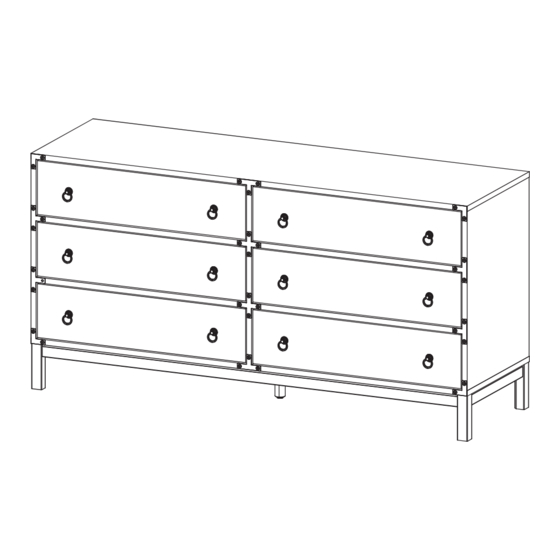
Model# CHS9601
Product Dimensions: 61"Wx19"Dx31"H
WARNING :
WEIGHT CAPACITY:
DRAWER LOAD CAPACITY 22 LBS
Warning : Do not stand on chest.
Warning : Do not over torque bolts.
103.6 LBS.
Advertisement

Related Manuals for Safavieh Furniture CHS9601


Summary of Contents for Safavieh Furniture CHS9601
- Page 1 *If you are having difficulty, our friendly Customer Care team is always here to help. Please email customersupport@safavieh.com PREPARATION Model# CHS9601 *Before beginning assembly of product, make sure all parts are present. Compare parts with part contents list and hardware contents list.
-
Page 2: Hardware List
Hardware List HW1x44 HW2x14 HW3x30 HW4x50 HW5x12 HW6x14 Ø 6 x 30 mm Ø 6 x 35 mm Ø 15 mm Ø 12 mm Ø 8 x 30 mm M 7 x 50 mm HW7x2 HW8x28 HW9x36 HW10x36 HW11x36 HW12x24 M 4.5 x 12.5 mm M 6 x 10.5 mm M 3.5 x 13 mm... - Page 3 Part List & HW For Mul�-Box Items Piece Descrip�on Carton Call Piece Descrip�on Carton Call Top Board 1 of 2 Cambolt 2 of 2 1 of 2 Bo�om Board CamLock Big 2 of 2 Side Board Le� 2 of 2 2 of 2 CamLock Small Side Board Right...
- Page 4 PREPARATION *Before beginning assembly of product, make sure all parts are present. Compare parts with part contents list and hardware contents list. *If any part is missing or damaged, do not a�empt to assemble the product. *Es�mated Assembly Time: 90 minutes. *Tools Required for Assembly (included): Allen Key *If you are having difficulty, our friendly Customer Care team is always here to help.
- Page 5 RM35A RM35A STEP6: Insert Dowel Middle (HW4) into Side Board Le� (C), Side Board Right (D) and Back Drawer (O). STEP5: Insert Cambolt (HW1) into Top Board. Con�nue with securing part of the metal runner (HW RM35A ) Insert Dowel Middle (HW4) into Support Board (N) into posi�on as the above image, using screw M6x10.5mm (HW9).
- Page 6 STEP9: A�ach Support Board (N) Between Center Board (P) and STEP10: Insert Camlock Big (HW2) and �ghten it using screwdriver. Side Board Right (D) and insert Dowel Big (HW20). Please ensure the Dowel Big (HW20) passed through the hole at Center Board and succesfully inserted to holes at the Support Board (N).
- Page 7 BC410 ± 2 mm STEP14: Now let’s combine the bo�om skirt. Start with installing Corner Brace (HW BC410) into Bo�om Skirt 2 (G) STEP13: Insert Bo�om Board (B), secure with Screw M7x50mm (HW6), using Screw M4.5x12.5mm (HW8). �ghten screws using Allen Key (HW7). Do not over�ght screw yet, leave around 2mm gap.
- Page 8 STEP18: Bring the assembled bo�om skirt and insert into Bo�om Board STEP17: Insert Dowel Middle (HW4) into of the chest drawer.Secure the bo�om skirt by inser�ng assembled Bo�om skirt from previous step. Screw M6.4x53mm (HW16) �ghten with Allen Key (HW7). STEP19: Place the Leg (E) on the center corner brace and STEP20: Install Moun�ng Plate (PM2) and secure with insert the screw M6x25mm (HW21) with Allen Key (HW7) into the leg,...
- Page 9 LC13A1 STEP22: Bring the chest drawer upright, Install Plat L (HW18), STEP21: Insert Center Leg (LC13A1) into Moun�ng Plate by rota�ng Plat T(HW19) and Plat + (HW22) into the provided holes at clockwise un�l �gtened. front edges of the chest drawer.Secure with screw M 6.4x14mm (HW17), �ghten using Allen Key (HW7).
- Page 10 TIPPING RESTRAINTS KIT INSTALLATION GUIDANCE Different wall materials require unique wall fasteners. The wall plugs (AA2) and screws (AA3) are designed for fixing to concrete walls only. Please consult your local hardware store to ensure you are using the correct hardware for your wall type. AA1 x 2 AA2 x 4 AA3 x 4...
Need help?
Do you have a question about the CHS9601 and is the answer not in the manual?
Questions and answers