Table of Contents
Advertisement
Quick Links
Advertisement
Table of Contents

Subscribe to Our Youtube Channel
Related Manuals for Seco SANTOKA 10.1 SG IPS


Summary of Contents for Seco SANTOKA 10.1 SG IPS
- Page 1 SANTOKA 10.1 SG IPS Cortex -A9 Flush Mount ® ® Product Manual...
- Page 2 15.03.2018 Page 19 New Picture RS485 Pin 6 to 11 Page 18 add Text for Pin1, Page 16 add new 08.12.2018 Capitle 5.2 " connecting the HMI device" 26.08.2019 Change address 17.12.2021 SECO CI Update 2022 Online support on edge.seco.com...
-
Page 3: Table Of Contents
Annex F: Guidelines and Standards ..............33 RoHS Declaration ...................33 Supplier Declaration – Directive EG 1907/2006 REACH ......33 F-3 UL Certification ....................33 SECO Northern Europe Conformity Statement .........34 Annex G: Common Documentation ..............35 Warranty hints ....................35 Field of Application..................36 Annex H: Technical Support ................ -
Page 4: Introduction
SANTOKA Introduction Thank you very much for purchasing a SECO Northern Europe product. Our products are dedicated to professional use and therefore we suppose extended technical knowledge and practice in working with such products. The information in this manual is subject to technical changes, particularly as a result of continuous product upgrades. -
Page 5: Safety Hints
Please read this section carefully and observe the instructions for your own safety and correct use of the device. Observe the warnings and instructions on the device and in the manual. SECO Northern Europe embedded systems have been built and tested by us and left the company in a perfectly safe condition.In order to maintain this condition and ensure safe operation, the user must observe the instructions and warnings contained in this manual. - Page 6 PRODUCT MANUAL SANTOKA IV. Approvals The SANTOKA may be equipped with a certified transmitting module. The internal / external antenna(s) used for this module must provide a separation distance of at least 2 cm from all persons and must not be co-located or operating in conjunction with any other antenna or transmitter.
-
Page 7: Product Introduction
Type Plate and Device Information For service and later identification of the device, the type plate contains important information. 25,4 Position of Typelabel Art.No.: 900-0000R SECO Northern Europe article number Model: SANTOKA x1 Product name and configuration S/N: YY-WW Production date (week/year) -
Page 8: Product Names And Variants
PRODUCT MANUAL SANTOKA Product Names and Variants Product name definition: SANTOKA <CPU> <7.0> <BX> <PCT> <IPS> <additional description> <Vx.y.z> Explanation: SANTOKA Product family name (invariable) <CPU> x1, x2, x2l, x4, x4P (number of cores inside the i.MX6 processor) <7.0> Display size in inch <BX>, <SG>, <OF>... -
Page 9: Related Documents And Online Support
PRODUCT MANUAL SANTOKA Related Documents and Online Support This document contains operating system specific information. The following additional documentations are available: OPERATING SYSTEMS Contains information about Linux BSP with development environment Linux Yocto Jethro Linux Embedded System Yocto (Codename: Jethro, Version 3.0) includes first information about the bootloader Flash-N-Go https://bit.ly/3lwp6an Linux Yocto Rocko... -
Page 10: Technical Data
PRODUCT MANUAL SANTOKA Technical Data CPU Type i.MX6Solo i.MX6Dual i.MX6Quad i.MX6QuadPlus Core Class Cortex ® ® Core Clock 1 GHz NEON for SIMD media acceleration and VFP operations; Multi-format HD 1080p video decoder and HD Features 720p video encoder hardware engine; L1 cache, 32 KB for instruction, 32 KB for data 512 KB L2 cache 1 MB L2 cache HW Accelerators... - Page 11 PRODUCT MANUAL SANTOKA Housing Front 3.0 mm toughened glass, RAL 9005 Frame None Rear ABS-PC/1.4016 stainless steel, foam seal Ingress Protection Front IP 66/Rear IP20 Device Dimensions W x H x D 264.3 x 181.1 x 37.7 mm Weight tbd. Power Supply Supply Voltage Nom.
-
Page 12: Block Diagram Sbc
PRODUCT MANUAL SANTOKA Block Diagram SBC Block Diagram SANTOKA 24 V i.MX6 Step Down 2-pole Molex Converter 2x Display LVDS LVDS0 20-pole Hirose LVDS1 Power PMIC 12V Supply 5V Supply Battery GPIO Backlight CR1220 PWM1_OUT 12-pole Molex Battery Res.Touch RC 1 Touchscreen I2C-3 Controller... -
Page 13: Connectors
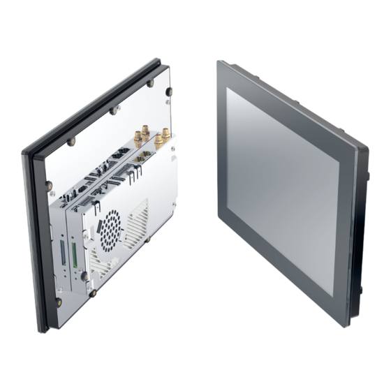
PRODUCT MANUAL SANTOKA Connectors As this manual describes a boxed version, only the external interfaces will be mentioned in the following chapter. X117 (Exemplary Illustration. It shows the fully equipped SANTOKA 10.1" BX PCT.) Pos. Description Wi-Fi/Bluetooth Antenna Connectors Ethernet (X117 1+2) Power (X1) CAN/RS-485 Interface (X39) Optional with Galvanic Isolation... - Page 14 PRODUCT MANUAL SANTOKA (Exemplary Illustration (cutout) both sides) Pos. Description Reset Switch (SW1) Bootselect Switch (SW2) SD Card Slot (X31) Power LED (D30) For the function of this switch please refer to the Flash N Go User Manual.
-
Page 15: Installation And Start Up
PRODUCT MANUAL SANTOKA Installation and Start Up The content of this document is limited to explain the device connectors and how to access SANTOKA via FTP over your local area network (LAN) within a few seconds. For advanced hardware specifications and software support, please refer to chapter „3.3 Related Documents and Online Support“... -
Page 16: Connecting The Hmi Device
PRODUCT MANUAL SANTOKA Connecting the HMI device Notice An incorrectly dimensioned power supply can destroy the HMI device. Use a DC power supply with adequate amperage; see Chapter 4. Technical Data Notice Safe electrical isolation For the DC supply, use only power supply units with safe electrical isolation in accordance with IEC 60364-4-41 or HD 384.04.41 (VDE 0100, Part 410), e.g. -
Page 17: Internal And External Interfaces
PRODUCT MANUAL SANTOKA Internal and External Interfaces Wi-Fi and Bluetooth Antenna Connectors Wi-Fi connector Bluetooth connector Header: SMA (RP-SMA optional) Ethernet (X117) (1+2) Name Description Information Rx/Tx might be swapped (Auto-MDIX) SPARE 1 +/- might be swapped (Autom. polarity correction) SPARE 2 Header: RJ45 Green LED (link) is default off and turns on when link is detected. -
Page 18: Power (X1)
PRODUCT MANUAL SANTOKA Power (X1) Name Description Level DC Ground Vcc_In DC Input voltage Nom. 13 to 32 V DC Header: Molex 43045-0200 Micro-Fit 2p Plug: Molex 43025-0200 Micro-Fit 2p, crimp contact Molex 43030-0007 Shielding with 6,3 mm male spade terminal connector. Pin 1 (GND) is connected to frame/housing. -
Page 19: Can/Rs-485 Interface (X39)
PRODUCT MANUAL SANTOKA CAN/RS-485 Interface (X39) Name Description Level GND_CAN_RS485 Ground for CAN and RS485 group CAN1_TERM To enable CAN1-Termination, bridge with CAN1_H CAN1_H CAN bus 1 high +24 V CAN1_L CAN bus 1 low +24 V CAN1_TERM To enable CAN1-Termination, bridge with CAN1_L RS485_TERM To enable RS485-Termination: bridge with RS485_A CAN1 Termination... -
Page 20: Usb Host (X34)
PRODUCT MANUAL SANTOKA USB Host (X34) Name Description Level USB_H1_VBUS Power supply +5 V DC max 500mA USB_H1_DN Data minus (D-) USB_H1_DP Data plus (D+) Ground Header: USB Type A USB Host (X113) Name Description Level USB_H1_VBUS Power supply +5 V DC max 500mA USB_H1_DN Data minus (D-) USB_H1_DP... -
Page 21: Hdmi (X111)
PRODUCT MANUAL SANTOKA HDMI (X111) Name Description Level D2 + TMDS Data2+ TMDS Data2 shield D2 - TMDS Data2- D1 + TMDS Data1+ TMDS Data1 shield D1 - TMDS Data1- D0 + TMDS Data0+ TMDS Data0 shield TMDS Data0- CK + TMDS Clock+ TMDS Clock schirm CK -... -
Page 22: Rs-232/Rs-232 (X13)
PRODUCT MANUAL SANTOKA RS-232/RS-232 (X13) Name Description Level Ground RS232_TXD1 Port#1: Transmit data (Output) RS232_RXD1 Port#1: Receive data (Input) RS232_RTS1 Port#1: Request-to-send (Output) RS232_CTS1 Port#1: Clear-to-send (Input) Ground RS232_TXD2 Port#2: Transmit data (Output) RS232_RXD2 Port#2: Receive data (Input) RS232_RTS2 Port#2: Request-to-send (Output) RS232_CTS2 Port#2: Clear-to-send (Input) Header: Molex 43045-1000 Micro-Fit 10p... -
Page 23: Usb Otg (X20)
PRODUCT MANUAL SANTOKA 6.10 USB OTG (X20) Name Description Level USB_OTG_VBUS Power supply +5 V DC max 500mA USB_OTG_DN Data minus (D-) USB_OTG_DP Data plus (D+) USB_OTG_ID Device ID Ground Header: Micro-USB Type AB 6.11 SD Card Slot (X31) Name Description Level DAT3... -
Page 24: Power Led (D30)
PRODUCT MANUAL SANTOKA 6.12 Power LED (D30) Should be green if the device is powered up. 6.13 Bootselect Switch (SW2) Push during a power on sequence to boot into the secondary OS. 6.14 Reset Switch (SW1) Push for a power on reset. -
Page 25: Battery-Holder (X125)
PRODUCT MANUAL SANTOKA 6.15 Battery-Holder (X125) Name Description Level Supply CR1220 Ground Header: AUK BH19VWG-R5H-H Battery: CR1220... -
Page 26: 6.16 Battery Specifications
PRODUCT MANUAL SANTOKA Battery 6.16 Battery Specifications The internal baseboard is equipped with a Primary Lithium battery (type CR1220), which has a typical lifetime of 8 years. Type SECO Northern Europe Article Number Battery type CR1220 010-0059R Manufacturer Model Varta CR1220 Alpha 3 Manufacturing Ltd. -
Page 27: 6.17 Replacement Of The Internal Battery
PRODUCT MANUAL SANTOKA 6.17 Replacement of the Internal Battery The internal battery is placed as per figure below. For replacement, the SD-card and the back cover have to be removed. The device shall be opened by authorized and skilled personnel only. Danger of electric hazard! First before opening, please make sure that the unit is completely disconnected from any power supply, direct or indirect. -
Page 28: Annex A: Technical Drawing
Annex A: Technical Drawing * front opening all round min. 0,5mm bigger! / * Gehäuseausschnitt umlaufend mind. 0,5mm größer vorsehen! 4,70 254,9* 05 06 07 08 09 29,46 195,98 speaker/ Lautsprecher 250,69 187,44 67,44 264,28 37,70 4,19 216,96 (AA) 47,44 Best View: all directions O-ring seal/ 9x M3... -
Page 29: Annex B: Quality And Incoming Inspections
PRODUCT MANUAL SANTOKA Annex B: Quality and Incoming Inspections Display and Touch Defect Type Specification Count(N) Bright Dots - Random One dot = one subpixel One pixel consists of Bright Dots - 2 Dots Adjacent/Pair three sub-pixels (dots), R, G and B. Bright Dots - 3 Dots Adjacent or more Dark Dots - Random Dot shape over all in display area and panel. -
Page 30: Annex C: Evaluation Criteria Of Standard Display Module
PRODUCT MANUAL SANTOKA Annex C: Evaluation criteria of standard display module Evaluated Zone 1: Areas in the immediate viewing area: dirt and dust enclosures / stains / striae / scratches from max. 500 μm (diameter) or 0.02 mm2 (surface), 5 pcs. per dm2 are permitted, but no clustering. -
Page 31: Annex D: Hardware Revision Information
PRODUCT MANUAL SANTOKA Annex D: Hardware Revision Information This document is applicable for all products listed below. Please note that customized variants might possibly not support all features listed herein. Additional features are documented in specific attachments. Platform Article Number Marking on PCB SANTOKA x1 10.1 SG IPS DI V1.2 900-3502R... -
Page 32: Annex E: Assembly Options
PRODUCT MANUAL SANTOKA Annex E: Assembly Options Wi-Fi / Bluetooth Some appliances require a wireless network connection. To be more flexible with regard to future Wi-Fi standards and regulations, we decided not to assemble this functionality directly onto the single-board-computer. We recommend an external USB or miniPCIe solution. Drivers for both versions will be included in the related operating systems. -
Page 33: Annex F: Guidelines And Standards
Supplier Declaration – Directive EG 1907/2006 REACH SECO Northern Europe is manufacturer of electronic products, thus - in the sense of REACH - we are so called „downstream users“. The products we supply to you are solely non-chemical products (goods). Moreover and under normal and reasonably foreseeable circumstances of application, the goods supplied to you shall not release any substance. -
Page 34: Seco Northern Europe Conformity Statement
These solutions are offered exclusively as OEM products. They do not include any application software that is intended for the end user. Therefore, we do not make any EU declarations of conformity in the name of SECO Northern Europe GmbH and do not provide the products with the CE mark. -
Page 35: Annex G: Common Documentation
If the product has been returned with or without prior notice and no failure or malfunction can be detected or the failure or malfunction is caused by inappropriate handling or the device has been returned after expiry of warranty period, SECO Northern Europe reserve the right to charge the user for repair or replacement. -
Page 36: G-2 Field Of Application
If you intend to use these products in applications as quoted in (II) we highly recommend a personal contact with our consultants and/or technical sales team. (I) Recommended application areas for SECO Northern Europe embedded systems Even for these applications, we recommend to get in contact with our technical sales team. We offer a wide range of support, even at an early stage of evaluation and/or design-in phase. -
Page 37: Annex H: Technical Support
SANTOKA Annex H: Technical Support Before contacting the SECO Northern Europe support team, please try to help yourself by the means of this manual or any other documentation provided by SECO Northern Europe or the related websites. If this does not help at all, please feel free to contact us. -
Page 38: Annex I: General Information
For exact technical drawings please refer to our sales team or product manager All other product or service names are the property of their respective owners. All rights reserved. Products subject to technical changes, improvements and misprints. © 2022 SECO Northern Europe GmbH...
Need help?
Do you have a question about the SANTOKA 10.1 SG IPS and is the answer not in the manual?
Questions and answers