Table of Contents
Advertisement
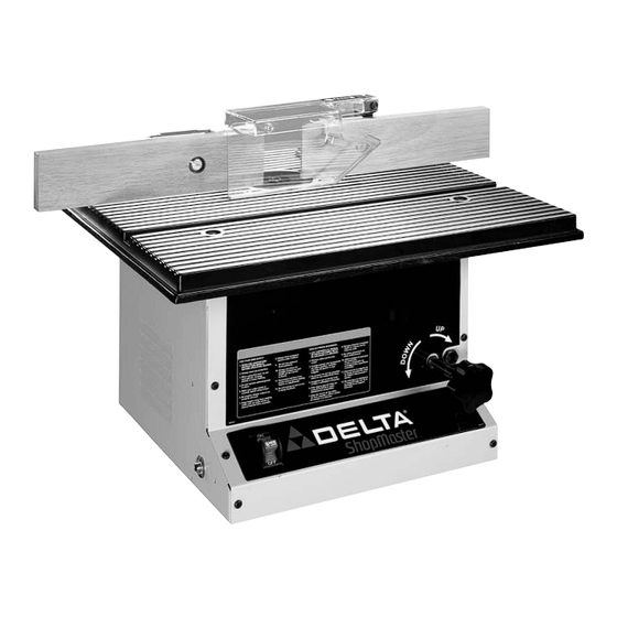
Router / Shaper
(Model SH100)
PART NO. 905582 - 05-15-02
Copyright © 2002 Delta Machinery
To learn more about DELTA MACHINERY
ESPAÑOL: PÁGINA 19
visit our website at: www.deltamachinery.com.
For Parts, Service, Warranty or other Assistance,
1-800-223-7278 (
1-800-463-3582).
please call
In Canada call
Get other manuals https://www.bkmanuals.com
Advertisement
Table of Contents

Summary of Contents for Delta ShopMaster SH100
- Page 1 Router / Shaper (Model SH100) PART NO. 905582 - 05-15-02 Copyright © 2002 Delta Machinery To learn more about DELTA MACHINERY ESPAÑOL: PÁGINA 19 visit our website at: www.deltamachinery.com. For Parts, Service, Warranty or other Assistance, 1-800-223-7278 ( 1-800-463-3582). please call In Canada call Get other manuals https://www.bkmanuals.com...
-
Page 2: General Safety Rules
If you have any questions relative to a particular application, DO NOT use the machine until you have first contacted Delta to determine if it can or should be performed on the product. - Page 3 ADDITIONAL SAFETY RULES FOR FOR THE ROUTER/SHAPER WARNING: FAILURE TO FOLLOW THESE RULES MAY RESULT IN SERIOUS PERSONAL INJURY 1. DO NOT OPERATE THIS MACHINE UNTIL it is 21. USE A HEAVY WORKPIECE when shaping with assembled and installed according to the starting pin and collar(s).
-
Page 4: Motor Specifications
POWER CONNECTIONS A separate electrical circuit should be used for your machines. This circuit should not be less than #12 wire and should be protected with a 20 Amp time lag fuse. If an extension cord is used, use only 3-wire extension cords which have 3- prong grounding type plugs and matching receptacle which will accept the machine’s plug. -
Page 5: Extension Cords
OPERATING INSTRUCTIONS FOREWORD Delta ShopMaster Model SH100 Router / Shaper is an economical alternative to the production wood shaper. The Router / Shaper has a powerful, 9 amp, induction-type, ball bearing motor for long-lasting trouble free operation. The Router / Shaper also has a thermal overload protection which prevents motor overload. - Page 6 ROUTER / SHAPER PARTS Fig. 2 1. Router / Shaper 14. Foot (4) 2. 1¼" Open End Arbor Wrench 15. Pin 3. Collet Wrench 16. Overhead Cutter Guard 4. 3mm Hex wrench 17. Dust Chute 5. Left Hand Fence Body 18.
- Page 7 ASSEMBLY WARNING: FOR YOUR OWN SAFETY, DO NOT CONNECT THE MACHINE TO THE POWER SOURCE UNTIL THE MACHINE IS COMPLETELY ASSEMBLED. DO NOT OPERATE THIS MACHINE UNTIL YOU READ AND UNDERSTAND THE ENTIRE INSTRUCTION MANUAL FEET 1. Place the Router / Shaper upside down on a flat surface.
- Page 8 FENCE ASSEMBLY AND DUST CHUTE Two fence halves are supplied as standard equipment with the Router/Shaper. To assemble and install the fence assembly, proceed as follows: 1. NOTE: The fence body with the see-thru cutter guard (R) Fig. 7, assembled to it, is to be assembled to the right hand side of the table, when facing the front of the machine.
-
Page 9: Operating Controls And Adjustments
ASSEMBLING TABLE INSERT The table insert (A) is assembled in the table, as shown in Fig. 11. FASTENING ROUTER/SHAPER TO SUPPORTING Fig. 11 SURFACE IF DURING OPERATION THERE IS ANY TENDENCY FOR THE ROUTER/SHAPER TO TIP OVER, SLIDE OR WALK ON THE SUPPORTING SURFACE, THE ROUTER/SHAPER SHOULD BE SECURED TO THE SUPPORTING SURFACE. -
Page 10: Overload Protection
OVERLOAD PROTECTION The Router/Shaper is equipped with overload protection. If the motor shuts off, or fails to start due to overloading (cutting stock too fast; using dull bits and cutters; using the machine beyond its capacity or at low voltage, etc.), TURN THE SWITCH (A) FIG. -
Page 11: Wrench Storage
SEE-THRU CUTTER GUARD The see-through cutter guard (A) Fig. 20, should always be used when using the fence to guide the work. The guard (A) raises as the workpiece is pushed along the fence and lowers at the completion of the cut. Fig. - Page 12 5. Loosen adjustment bolt Fig. corresponding bolt at the rear of the machine (not shown.). 6. Carefully move the spindle height lock knob (E) Fig. 24, up or down until the metal rod (A) is 90 degrees to the table surface. Then tighten adjustment bolts (D) which were loosened in STEP 5.
- Page 13 INSTALLING ROUTER BITS 1. DISCONNECT MACHINE FROM POWER SOURCE. 2. Raise spindle to the maximum height and tighten lock knob. 3. This machine is supplied with a 1/2 inch collet (A) Fig. 27, that accepts 1/2 inch shank router bits. A 1/4 inch adapter sleeve (B) Fig.
- Page 14 INSTALLING OVERHEAD CUTTER GUARD An overhead cutter guard, shown in Fig. 31, is supplied as standard equipment with your Router/Shaper and should always be used for operations that require the fence to be removed. To install the overhead cutter guard, proceed as follows: 1.
-
Page 15: Operation
The following is an example of the setting-up and operational procedures when using the fence, collars and starting pin. Please review this information carefully before turning on the power to avoid damage to the machine or personal injury. WARNING: The use of accessories and attachments not recommended by Delta may result in risk of injuries. - Page 16 POSITION OF COLLARS 1. The collars may be used in any of the following po- sitions: above, below or between two cutters. CUTTER WORK COLLAR TABLE 2. When the collar is used below the cutter, as shown in Fig. 43, the progress of the cut can be observed at all Fig.
- Page 17 NOTES Get other manuals https://www.bkmanuals.com...
-
Page 18: Parts, Service Or Warranty Assistance
Two Year Limited Warranty Delta will repair or replace, at its expense and at its option, any Delta machine, machine part, or machine accessory which in normal use has proven to be defective in workmanship or material, provided that the customer returns the product prepaid to a Delta factory service center or authorized service station with proof of purchase of the product within two years and provides Delta with reasonable opportunity to verify the alleged defect by inspection.
Need help?
Do you have a question about the ShopMaster SH100 and is the answer not in the manual?
Questions and answers