Table of Contents
Advertisement
Quick Links
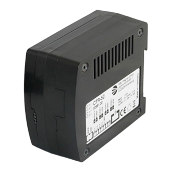
Mechanical Integration
The CTR-52 controller is supplied with top hat rail mounting and
plug-contacts for the LED light, control signals and input power.
More 2D and 3D drawings can be found online:
www.mbj-imaging.com
Safety Notes
Before working with this unit read the warning and application instruc-
tions carefully and completely.
1. The device is designed for indoor use only.
2. Health – The device must be disconnected from the power source
before the installation and/or maintenance can start. The device
must not be used when a failure may cause personal injury.
3. Electricity – The housing is electrically isolated from the ground of
the power supply. Exceeding the permissible operating voltage or
exceeding the maximum allowed switching current per channel can
lead to the destruction of the device or to a significant shortening of
the lifetime of the connected LED lighting module.
4. Mechanical integration – The controller is made for top hat rail
mounting. A clip can be used to lock the unit to the top hat rail. For
optimal heat flow a left/right distance of 10mm to next unit is rec-
ommended.
Status LED's CTR-52
LED
Status
Meaning
LED 1
OFF
Channel 1 LED light not found
ON
Channel 1 LED light connected
LED 2
OFF
Channel 2 LED light not found
ON
Channel 2 LED light connected
LED 3
OFF
Channel 3 LED light not found
ON
Channel 3 LED light connected
LED 4
OFF
Channel 4 LED light not found
ON
Channel 4 LED light connected
LED 1-4
flashing
Error
Trigger Signals
Operating Manual
Technical Data
Controller CTR-52
CTR-52
4-Channel LED driver
Current controlled operation for continuous LED light
Voltage controlled operation for short, precise and high-power LED flashes
Full control via Modbus TCP/IP
MS Windows based control software and multi OS Python scripts
Synchronize flash control via the camera's 'exposure time'
4 opto-coupled trigger I/O lines with flexible assignment to the LED channels
Passive cooling and overheat protection
Different sequence modes for shape-from-shading application
MBJ Imaging GmbH
Jochim-Klindt-Straße 7
+49 41 02 77 89 0 - 31
22926 Ahrensburg, Germany
sales@mbj-imaging.com
www.mbj-imaging.com
03735.04 Manual MBJ Controller CTR-52, Juni 2023
Advertisement
Table of Contents

Related Manuals for mbj CTR-52


Summary of Contents for mbj CTR-52
- Page 1 Mechanical Integration Safety Notes Operating Manual The CTR-52 controller is supplied with top hat rail mounting and Before working with this unit read the warning and application instruc- plug-contacts for the LED light, control signals and input power. tions carefully and completely.
- Page 2 Unload flash capacitors visit: www.mbj-imaging.com/en/products/led-controller LED output is switched off 1) The CTR-52 factory setting of the operation mode is FLASH 150 mA, 300 µs. Other operating modes are selectable via the Modbus interface Application Samples for CTR-52 Controller Triggered light with PNP sourcing...
Need help?
Do you have a question about the CTR-52 and is the answer not in the manual?
Questions and answers