Table of Contents
Advertisement
Quick Links
Advertisement
Table of Contents

Related Manuals for Inovance MD500-EN1

Summary of Contents for Inovance MD500-EN1
- Page 1 User Guide MD500-EN1 Communication Expansion Card Date code 19011561 A00...
-
Page 2: Preface
Preface Preface ■ Introduction MD500 series Ethernet/IP communication card (hereinafter referred to as MD500-EN1 card) is an adapter card for Ethernet/IP fieldbus. It complies with international Ethernet/ IP bus standards and features high efficiency, flexible topology, and easy operation. This user guide describes the specifications, dimensions, installation, wiring, communication protocols, communication-related parameters, and communication examples of the MD500-EN1 expansion card. -
Page 3: Table Of Contents
3.3 Description of Data Responded to by the AC Drive .............16 4 Parameters Related to Communication ................17 4.1 Communication Card Type Setting ................17 4.2 IP Address Setting of MD500-EN1 Card ................17 4.3 Parameters of AC Drive Communication Card .............19 4.4 Parameter Related to Communication Control ............19 4.5 Parameters Related to Communication Monitoring ...........20... -
Page 4: Safety Instructions
4) Use this equipment according to the designated environment requirements. Damage caused by improper usage is not covered by warranty. 5) Inovance shall take no responsibility for any personal injuries or property damage caused by improper usage. Safety Levels and Definitions... - Page 5 Safety Instructions WARNING ◆ Do not install the equipment if you find damage, rust, or indications of use on the equipment or accessories. ◆ Do not install the equipment if you find water seepage, component missing or damage upon unpacking. ◆...
- Page 6 Safety Instructions DANGER ◆ Equipment installation, wiring, maintenance, inspection, or parts replacement must be performed by only professionals. ◆ Installation, wiring, maintenance, inspection, or parts replacement must be performed by only experienced personnel who have been trained with necessary electrical information.
- Page 7 Safety Instructions DANGER ◆ Before power-on, make sure that the equipment is installed properly with reliable wiring and the motor can be restarted. ◆ Before power-on, make sure that the power supply meets equipment requirements to prevent equipment damage or even a fire. ◆...
- Page 8 Safety Instructions Repair DANGER ◆ Equipment installation, wiring, maintenance, inspection, or parts replacement must be performed by only professionals. ◆ Do not repair the equipment at power-on. Failure to comply will result in an electric shock. ◆ Before inspection and repair, cut off all equipment power supplies and wait at least 10 minutes.
-
Page 9: Safety Signs
Safety Instructions Safety Signs For safe equipment operation and maintenance, comply with safety signs on the equipment, and do not damage or remove the safety labels. The following table describes the safety signs. Safety Sign Description ◆ Read the user guide before installation and operation. Failure to comply will result in an electric shock. -
Page 10: Product Information
U0-67 upon power-on after installing the card). The corresponding EDS file name is MD500P_EIP_V1.00.eds. This user guide is applicable only for the MD500-PLUS series AC drive. If you need to use the MD500-EN1 card with other AC drives, contact our technical support for details. -
Page 11: Interface Layout And Description
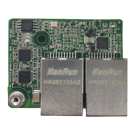
"Figure 1-3 MD500-EN1 interface layout"shows the hardware layout of the MD500-EN1 card. The pin header J7 on the back of the MD500-EN1 card is used to connect the AC drive. The MD500-EN1 card provides two network ports J4 and J6 for communication with Ethernet/IP master (or other slaves). - Page 12 Ethernet/IP fault indicator (red) ◆ After the MD500-EN1 card is installed, J4 is on the left and J6 is on the right when you face the RJ45 interface. The two interfaces are direction- insensitive. Connect either of them to the PLC.
-
Page 13: Installation And Wiring
AC drive and wait about 10 minutes until the charging indicator on the AC drive becomes off. Then, insert the MD500-EN1 card into the AC drive and fasten the screws to avoid damage caused by external signal cable tension on the signal socket between boards. -
Page 14: Wiring
2 Installation and Wiring 2.2 Wiring 2.2.1 Ethernet/IP Topology The topological structures supported by Ethernet/IP include bus, star, and tree topologies. Various networking can be realized by using switches correctly. Figure 2-3 Bus topology Figure 2-4 Star topology - 13 -... -
Page 15: Emc Wiring
3 Ethernet/IP Communication Protocol Figure 3-3 Tree topology 2.2.2 EMC Wiring ■ During on-site installation and commissioning, the signal cables and power cables must be laid in different ducts. Never bundle the signal cables and power cables together to prevent communication interference. ■... -
Page 16: Ethernet/Ip Communication Protocol
3 Ethernet/IP Communication Protocol 3.1 Description of I/O Messages Data 24 I/O Messages are available in the MD500-EN1 expansion card for data transmission, in which 12 I/O messages transmit data from master station to slave station and another 12 I/O messages transmit data from slave station to master station. -
Page 17: Description Of Data Responded To By The Ac Drive
3 Ethernet/IP Communication Protocol Description of data transmitted by the master Used to change the function parameter values (groups F and A) in real time I/O Messages2 to I/ without writing the values into the EEPROM. FE-02 to FE-11 correspond to I/O O Messages11 Messages2 to I/O Messages11. -
Page 18: Parameters Related To Communication
4 Parameters Related to Communication 4.1 Communication Card Type Setting After powering on the AC drive, set FD-00 and FD-01 to 9 (baud rate: 115200 bps) and 3 (no check, 8-N-1) respectively to enable communication between the MD500-EN1 card and the AC drive. Parameter... - Page 19 4 Parameters Related to Communication Parameter No. Parameter Name Setting Range Description Subnet mask of Used to set subnet mask of FD-42 FD-45 0-255 expansion card Ethernet/IP expansion card. Gateway address of Used to set gateway address of FD-46 FD-49 0-255 expansion card Ethernet/IP expansion card.
-
Page 20: Parameters Of Ac Drive Communication Card
4 Parameters Related to Communication Case Symptom Solution The device powered on first Both devices support IP uses the IP address and address conflict detection. The continues to operate. The two devices are powered on device powered on later one after another. enters the conflict mode. -
Page 21: Parameters Related To Communication Monitoring
Signed data, 1 rpm 29463 By default, when the MD500-EN1 card is used, the written I/O Messages0 and I/O Messages1 are mapped to U3-17 and U3-16, respectively. If any command or frequency cannot be written to the AC drive correctly but I/O Messages2 to I/O Messages11 can be written and F0-02 and F0-03 are set to 2 and 9 respectively, check whether FE-00 and FE-01 are set to U3-17 and U3-16 respectively. - Page 22 4 Parameters Related to Communication Parameter Name Unit Decimal Address U0-13 Length value 28685 U0-14 Load speed display 0.001 Hz 28686 U0-15 PID reference 28687 U0-16 PID feedback 28688 U0-17 PLC stage 28689 U0-18 Pulse input reference (Hz) 0.01 kHz 28690 U0-19 Feedback speed (Hz)
- Page 23 0.1 A 28743 By default, when the MD500-EN1 card is used, the I/O Messages0 and I/O Messages1 being read are mapped to U0-68 and U0-69, respectively. If any state or operating frequency cannot be read correctly but I/O Messages2 to I/O Messages11 can be read, check whether FE-20 and FE-21 are set to U0-68 and U0-69 respectively.
-
Page 24: Communication Examples
5 Communication Examples 5 Communication Examples 5.1 AB L16ER Controller as the Master This example uses Studio5000 Logix Designer version 32.00.00 with 1769-L16ER-BB1B being the master. The information such as IP address has been configured according to the user guide. Connect either network port on the expansion card. Set F0-02, F0-03, FD-00, and FD-01 to 2, 9, 9, and 3 respectively before using the expansion card. - Page 25 5 Communication Examples Step 2: Import the ESD file. Choose Tools > EDS Hardware Installation Tool in the menu bar. Click Next and then select Register an EDS file(s). Choose EDS file on your computer and then click Next. - 24 -...
- Page 26 5 Communication Examples Keep clicking Next before the finish button shows and then click Close. Step 3: Set the IP address of the expansion card, herein, take the static IP address as an example. Set FD-37 – FD-49 to 0, 192.168.0.6, 255.255.255.0, and 192.168.0.1 respectively. Step 4: Configure Studio5000 project.
- Page 27 5 Communication Examples Locate EIP_Card on the interface and then click Create. The configuration dialog box appears. Enter the preceding set IP address and type in a name. Click Change in the General interface. Locate SINT and click to select INT. Next, Click OK and then Yes to proceed when an alert box appears.
- Page 28 5 Communication Examples Choose Logic > Monitor Tags in the menu bar. Unfold MD500:C.Data and click Style to convert data type to Hex. - 27 -...
- Page 29 5 Communication Examples The following parameters are used to configure PDO mapping. Every two parameters form a group. 0-23 indicates I/O Messages Mapping(T->O) and 24-47 indicates I/O Messages Mapping(O->T). Data[0]=0x44 and Data[1]=0x70 shown in the figure represent that TPDO1 is mapped to U0-68. By default, I/O Messages Mapping(T->O)[0] is mapped to U0-68, I/O Messages Mapping(T->O)[1] is mapped to U0-69, I/O Messages Mapping(O->T)[0] is mapped to U3-17, and I/O Messages Mapping(O->T)[1] is mapped to U3-16.
- Page 30 5 Communication Examples Step 5: Use explicit messaging for data transmission. Open programming section in PLC, and choose Input/Output > MSG. Enter a name in the field that holds the question mark and right-click New"Read". Click Create. - 29 -...
- Page 31 5 Communication Examples Click the ellipsis on the right side of MSG. Configure according to the following figures. - 30 -...
- Page 32 5 Communication Examples Select Get Attribute Single to read parameters while select Set Attribute Single to write parameters. Class and Attribute are set to fixed 0x93 and 0x9 respectively. Instance converts parameters required to be read to decimal format. FD-13 (FD0D) as shown in the figure is converted to the decimal format, which is 64781.
- Page 33 5 Communication Examples Click Communication to choose the AC drive. - 32 -...
- Page 34 5 Communication Examples Click OK. The master station will read this parameter and store the data into the selected variable. The value of this variable can be viewed in Logic-Monitor Tags. Parameters being written are shown in the following figure. - 33 -...
- Page 35 5 Communication Examples Step 6: Enable DHCP function. Note: IP address assigned from DHCP server cannot be saved at power-down state. Set FD-37 to 1 to enter DHCP mode. Re-power on the AC drive and then connect the computer and the AC drive to the same network. Choose Start >...
- Page 36 5 Communication Examples Device request can be seen in the software after power on. Right-click to select Add Relation. Set the IP address and click OK. The IP address is written to the device. - 35 -...
-
Page 37: Inovance Am600 Controller As The Master
5 Communication Examples 5.2 Inovance AM600 Controller as the Master This example uses InoProShop version 1.5.2 with AM600 controller. The information such as IP address has been configured according to the user guide. Connect either network port on the left or right of the expansion card. Set F0-02, F0-03, FD-00, and FD- 01 to 2, 9, 9, and 3 respectively before using the expansion card. - Page 38 5 Communication Examples Step 2: Import the ESD file and add a slave station. Open network configuration window, click PLC and select Ethernet/IP master as current communication protocol. Click Import EDS file to import EDS file of EIP card. Import device from Network Device List on the right side of the window. - 37 -...
- Page 39 5 Communication Examples Step 3: Configure the slave parameters. Set the IP address of the slave station. Click Connections on the left side of window to configure I/O messages mapping. Input I/O Messages Mapping(T->O)[x] indicates that the data is mapped from slave to master station.
- Page 40 5 Communication Examples Step 4: Configure the IP address of the master station. Scan for a network and select the master station to be configured. Assign an IP address for the master network port. - 39 -...
- Page 41 5 Communication Examples Download the project to the PLC. View I/O Messages(O->T) and I/O Messages(T->O) in Ethernet/IP I/O mapping. - 40 -...
-
Page 42: Troubleshooting
3. Use the Cat5e shielded twisted error) reported by damaged or connected pair (STP) network cable as required. the AC drive during incorrectly. Check that the MD500-EN1 card is running 3. The AC drive suffers grounded correctly. Eliminate the external interference. external interference. Contact the agent or Inovance for technical support if necessary. - Page 43 Check whether other devices have the same IP Bit 2 IP address conflict address as this device. MAC address not programmed Contact Inovance or the agent for technical Bit 1 or lost support. Contact Inovance or the agent for technical...
- Page 44 Fax: +86-755-2961 9897 http: //www.inovance.com Suzhou Inovance Technology Co., Ltd. Add.: No. 16 Youxiang Road, Yuexi Town, Wuzhong District, Suzhou 215104, P.R. China *19011561A00* Tel: +86-512-6637 6666 19011561A00 Fax: +86-512-6285 6720 http: //www.inovance.com Copyright Shenzhen Inovance Technology Co., Ltd.
Need help?
Do you have a question about the MD500-EN1 and is the answer not in the manual?
Questions and answers