Sign In
Upload
Download
Table of Contents
Contents
Add to my manuals
Delete from my manuals
Share
URL of this page:
HTML Link:
Bookmark this page
Add
Manual will be automatically added to "My Manuals"
Print this page
×
Bookmark added
×
Added to my manuals
Manuals
Brands
ATREA Manuals
Fan
DUPLEX RA5
Use, maintenance and installation manual
ATREA DUPLEX RA5 Use, Maintenance And Installation Manual
Hide thumbs
1
Table Of Contents
2
3
4
5
6
7
8
9
10
11
12
13
14
15
16
17
18
19
20
21
22
23
24
25
26
27
28
29
30
31
32
33
34
35
36
37
38
39
40
41
42
43
44
45
46
47
48
page
of
48
Go
/
48
Contents
Table of Contents
Troubleshooting
Bookmarks
Table of Contents
Table of Contents
General Information, Glossary of Terms
Sections of the Manual
Introduction
Description of the Unit
Abbreviations, Marking
Important Information
Intended Scope of Application
Scope of Supply, Accessories, Transportation and Storage
Storage and Transportation
Scope of Supply
Mandatory Accessories
Optional Accessories
Integrated Heating or Cooling Coils
External, Duct Air Pre-Heaters
Other Accessories
Selecting a Suitable Air Conditioner for DUPLEX R5 Units
Description and Technical Data
Technical Parameters
Description of Main Components of Duplex R5 Units
Drawing and Description of Main Components of DUPLEX RA5 Units
Drawing and Description of Main Components of DUPLEX RK5 Units
Drawing and Description of Main Components of DUPLEX RB5 Units
Configuration Options 10 / 11 for RA5 and RK5 Units
Optional Configurations of RB5 Units
Descirption of Air Filters
Unit Assembly and Installation
Installation of R5 Units
Fitting a Reducer in RB5 Units
Changing the Position of the Recirculated Air Fan Outlet in RB5 Units
Connecting the Condensate Drain
General Condensate Drain Arrangmenet in DUPLEX R5 Units
Connecting the Condensate Drain Line in DUPLEX R5 Units
Wiring and Cable Entry Point
Connecting the Hot Water Coil
Connecting the Integrated Electric Heater
Connecting the Cold Water Coil
Connecting the Direct Evaporator / Condenser
Installing the Zone Damper in the Bottom Outlet in RA5 and RK5 Units
Installing Controllers
CP Touch Controller
Instrumentation and Control, Electrical Wiring
RD5 Control System with CP Touch Controller
Connecting the Controller to the Unit
Starting the Display
Symbols and Their Meaning
Symbols on the Main Screen
Navigation Symbols
Symbols Permanently Displayed on the Main Screen
Power" Block
Power Settings in Recirculated Air Mode
Mode" Block
List of Modes
Temperature" Block
Zone" Block
User Settings
Parameters
Control
Přepnutí HS/NHS
HS/NHS Temperature
Current Season
Control Settings
IN1 Input Blocking (No/Hs /NHS)
IN2 Input Blocking (No/Hs /NHS)
Heating Hysteresis
Cooling Hysteresis
Bank Holidays
School Holidays
Holiday / Party
Setting the Weekly Program
Copying Days
Network Settings
Texts
Display Settings
Time Zone Setting
Daylight Saving Time
SW Information
Filter Replacement Indication
Table of Alarms and Notifications
Forgetful Operator
Bypass Dampers
Control System RD5 with CP Touch Controller
Commissioning
Connecting to the Mains Power Supply
Required Protection and Mains Power Supply Connection
Connecting and Installing Sensors
Warranty
Maintenance and Service
Replacing G4/F7 Air Filters - Fabric Version
Replacement and Cleaning of the ODA Pre-Filter - Expanded Metal
Replacement and Cleaning of ODA and ETA Fabric Filters
Replacement and Maintenance of the Main Fabric Filter for RCA Units
Cleaning the Plastic Heat Recovery Exchanger
Sliding out the Heat Recovery Exchanger from RB5 Units
Sliding out the Heat Recovery Exchanger from RA5 and RK5 Units
Cleaning Controllers
Cleaning Other Parts of the Unit - Minor Maintenance
Spare Parts, Repairs
Breakdowns, Safety Instructions
Faults and Troubleshooting
Appendices
Product Data Sheet
RD5 Wiring Diagram - Internal Wiring
RD5 Wiring Diagram - Optional Accessories
Advertisement
Quick Links
Download this manual
Version: 07
EN
Issue:
2021_09
Code: R29_V07_2021_09
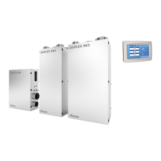
DUPLEX RA5, RB5, RK5
1
Table of
Contents
Previous
Page
Next
Page
1
2
3
4
5
Advertisement
Table of Contents
Need help?
Do you have a question about the DUPLEX RA5 and is the answer not in the manual?
Ask a question
Questions and answers
Related Manuals for ATREA DUPLEX RA5
Fan ATREA DUPLEX EC Series Disassembling Manual
Separate part of the ventilation unit (5 pages)
Fan ATREA DUPLEX RB5 Use, Maintenance And Installation Manual
(48 pages)
Fan ATREA DUPLEX RK5 Use, Maintenance And Installation Manual
(48 pages)
Fan ATREA DUPLEX 250 Easy Manual
Compact ventilation units with heat recovery and ec fans (4 pages)
This manual is also suitable for:
Duplex rb5
Duplex rk5
Table of Contents
Save PDF
Print
Rename the bookmark
Delete bookmark?
Delete from my manuals?
Login
Sign In
OR
Sign in with Facebook
Sign in with Google
Upload manual
Upload from disk
Upload from URL


Need help?
Do you have a question about the DUPLEX RA5 and is the answer not in the manual?
Questions and answers