
Related Manuals for TECHNI-PRO TNP477

Summary of Contents for TECHNI-PRO TNP477
- Page 1 Operating Instructions for AC/DC TRMS CLAMP METER Please read this manual before switching the unit on. Important safety information inside.
-
Page 3: Table Of Contents
AC/DC TRMS CLAMP METER Page Content 1.Introduction................. 2.Safety..................2-1.International Safety Symbols........... 2-2.PER IEC1010 OVERVOLTAGE INSTALLATION CATEGORY....2-3.Safety Notes................2-4.Input Limits................3.Description.................. 3-1.Meter Description..............3-2.Display Icons Description............4.Function..................4-1.Data Hold................4-2.LCD Backlight................. 4-3.MAX/MIN................4-4.Peak Hold................4-5.INRUSH................... 4-6.Automatic Power OFF with Disable........... 4-7.Low Battery Indication............. -
Page 4: Introduction
AC/DC TRMS CLAMP METER 1.Introduction • The True RMS Clamp Meter measures DC Current up to 1000A and AC Current up to 3000A. • Other functions include AC/DC Voltage, Resistance, Continuity, Diode Test, Capacitance, Frequency, Duty Cycle and Temperature. • A built-in flashlight and non-contact AC voltage detector provide added convenience. •... -
Page 5: 2-3.Safety Notes
AC/DC TRMS CLAMP METER 2-3.Safety Notes • Do not exceed the maximum allowable input range of any function. • Do not apply voltage to meter when resistance function is selected. • Set the function switch OFF when the meter is not in use. •... -
Page 6: Description
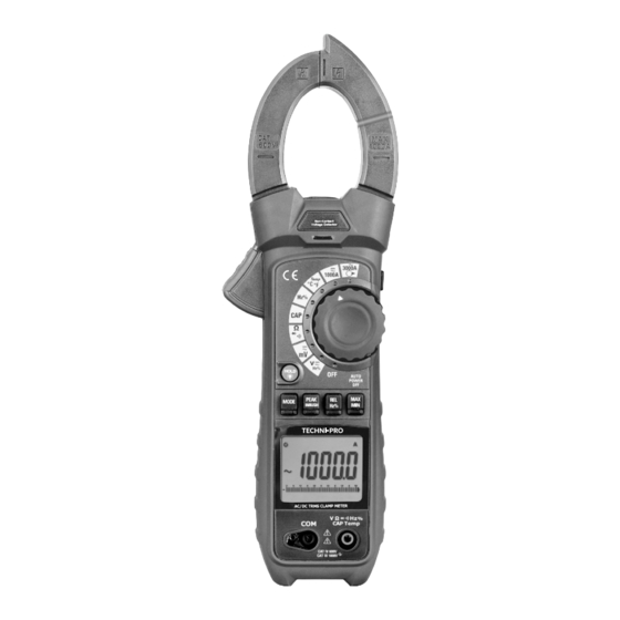
AC/DC TRMS CLAMP METER 3.Description 3-1.Meter Description 1-Current Clamp 2-Non-Contact AC Voltage Indicator Light 3-Clamp Trigger 4-Bluetooth/Flashlight Button 5-Rotary Function Switch 6-Data Hold/Backlight Button 7-MODE Select Button 8-PEAK/INRUSH Button 9-Relative/Hz Button 10-MAX/MIN Button 11-LCD Display 12-3000A AC Input Jack 13-COM Input Jack 14-Positive Input Jack 15-Flash Light LED 16-Battery Cover... - Page 7 AC/DC TRMS CLAMP METER Flexible Clamp CAT III 1000V CAT IV 600V MAX 3000A AC TRMS...
-
Page 8: 3-2.Display Icons Description
AC/DC TRMS CLAMP METER 3-2.Display Icons Description 1-Bluetooth 9-Analog Bargraph 2-Auto Power Off 10-Auto Range Mode 3-Units of Measure List 11-Data Hold 4-Direct Current 12-Peak Maximum/Maximum 5-Negative Reading Display 13-Peak Minimum/Minimum 6-Alternating Current 14-Relative Mode 7-Low Battery 15-DC Zero 8-Measurement Display Digits 16-Inrush Current 13 14... -
Page 9: Function
AC/DC TRMS CLAMP METER 4.Function 4-1.Data Hold • To freeze the LCD reading, press the HOLD/Backlight Button. While data hold is active, the HOLD icon appears on the LCD. • Press the HOLD/Backlight Button again to return to normal oper ation. -
Page 10: Operation
AC/DC TRMS CLAMP METER 5.Operation Notes: Read and understand all Warning and Caution statements in this operation manual prior to using this meter. Set the function select switch to the OFF position when the meter is not in use. 5-1.AC/DC Current Measurement WARNING: Disconnect the test leads before measuring with clamp. -
Page 11: 5-2.Ac/Dc Voltage Measurement
AC/DC TRMS CLAMP METER 5-2.AC/DC Voltage Measurement CAUTION: Do not measure voltages if a motor on the circuit is being switched ON or OFF. Large voltage surges may occur that can damage the meter. 1.S et the function switch to the VAC/DC or mVAC/DC Position. 2.I nsert the black test lead into the COM Input Jack and the red test lead into the Positive Input Jack. -
Page 12: 5-3.Resistance Measurement
AC/DC TRMS CLAMP METER 5-3.Resistance Measurement Note: Remove power from the device under test before measuring resistance. Ω 1.S et the function switch to the Position. 2.I nsert the black test lead into the COM Input Jack and the red test lead into the Positive Input Jack. 3. -
Page 13: 5-4.Continuity Measurement
AC/DC TRMS CLAMP METER 5-4.Continuity Measurement Ω 1.S et the function switch to the Position. 2.I nsert the black test lead into the COM Input Jack and the red test lead into the Positive Input Jack. 3. Press the MODE Button to select continuity “ ”. 4. -
Page 14: 5-5.Diode Test
AC/DC TRMS CLAMP METER 5-5.Diode Test Ω 1.S et the function switch to the Position. 2.I nsert the black test lead into the COM Input Jack and the red test lead into the Positive Input Jack. 3. Press the MODE Button to select continuity “ ”. 4. -
Page 15: 5-6.Capacitance Measurement
AC/DC TRMS CLAMP METER 5-6.Capacitance Measurement WARNING: To avoid electric shock, discharge the capacitor under test before measuring. 1.S et the function switch to the CAP Position. 2.I nsert the black test lead into the COM Input Jack and the red test lead into the Positive Input Jack. 3. -
Page 16: 5-7.Frequency/Duty Cycle Measurement
AC/DC TRMS CLAMP METER 5-7.Frequency/Duty Cycle Measurement 1.S et the function switch to the Hz% Position. 2.I nsert the black test lead into the COM Input Jack and the red test lead into the Positive Input Jack. 3.Touch the test probe tips across the part under test. 4.Read the Frequency value on the display. -
Page 17: 5-8.Temperature Measurement
AC/DC TRMS CLAMP METER 5-8.Temperature Measurement 1. Set the function switch to the TEMP Position. 2. Use the MODE Button to select °C or °F. 3. Insert the Temperature Probe into the COM and Positive Input Jack, observing polarity. 4. Touch the Temperature Probe head to the device under test, continue to touch the part under test with the probe until the reading stabilizes. -
Page 18: 5-9.Non-Contact Ac Voltage Measurement
AC/DC TRMS CLAMP METER 5-9.Non-Contact AC Voltage Measurement WARNING: Risk of Electrocution. Before use, always test the Voltage Detector on a known live circuit to verify proper operation. • Rotate the Function switch to any measurement position. • Place the detector probe tip on the conductor to be tested. If AC voltage is present, the NCV detector will turn on with a steady red light. -
Page 19: Maintenance
AC/DC TRMS CLAMP METER 6.Maintenance WARNING: To avoid electrical shock, disconnect the meter from any circuit, remove the test leads from the input terminals, and turn OFF the meter before opening the case. Do not operate the meter with an open case. 6-1.Cleaning and Storage •... -
Page 20: Specifications
AC/DC TRMS CLAMP METER 7.Specifications 7-1.Technical Specifications Function Range & Resolution Accuracy DC Current 1000.0A ±(2.5% + 5 digits) AC True RMS Current 3000.0A (Flexible Current Probe) ±(2.8% + 8 digits) (50 to 1000Hz) 1000.0A All AC Current ranges are specified from 5% of range to 100% of range. DC Voltage 500.00mV 5.0000V... - Page 21 AC/DC TRMS CLAMP METER Function Range & Resolution Accuracy Frequency 50.000Hz 500.00Hz 5.0000kHz 50.000kHz ±(0.3% + 2 digits) 500.00kHz 5.0000MHz 10.000MHz Sensitivity: 0.8Vrms min. at 20% to 80% Duty Cycle and <100kHz; 5Vrms min at 20% to 80% Duty Cycle and >100kHz. Duty Cycle 5.0 to 95.0% ±(1.0% + 2 digits)
-
Page 22: 7-2.General Specifications
AC/DC TRMS CLAMP METER 7-2.General Specifications Clamp Jaw Opening 1.9” (48mm) approx. 50.000 count backlit LCD Display Flexible Coil 140x180mm Continuity Check Threshold 50Ω; Test current <0.5mA Diode Test Test current of 0.3mA typical; Open circuit voltage 2.8VDC typical Low Battery Indication “... - Page 24 AC/DC TRMS CLAMP METER Rev.230314...
Need help?
Do you have a question about the TNP477 and is the answer not in the manual?
Questions and answers