Table of Contents
Advertisement
Quick Links
O
M
PERATOR'S
ANUAL
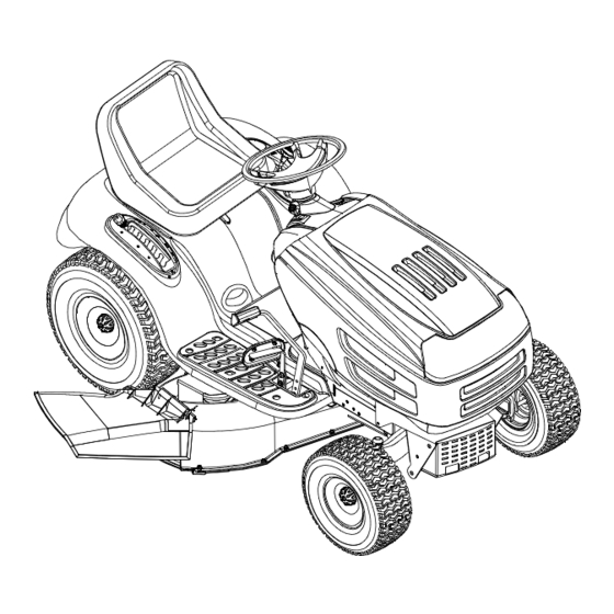
Automatic Lawn Tractor
Model U608H016
IMPORTANT: READ SAFETY RULES AND INSTRUCTIONS CAREFULLY
Warning:
This unit is equipped with an internal combustion engine and should not be used on or near any unimproved forest-
covered, brush-covered or grass-covered land unless the engine's exhaust system is equipped with a spark arrester meeting
applicable local or state laws (if any). If a spark arrester is used, it should be maintained in effective working order by the operator.
In the State of California the above is required by law (Section 4442 of the California Public Resources Code). Other states may have
similar laws. Federal laws apply on federal lands. A spark arrester for the muffler is available through your nearest engine authorized
dealer or contact the service department, P.O. Box 368022 Cleveland, Ohio 44136-9722.
MTD PRODUCTS, INC P.O. BOX 368022 CLEVELAND, OHIO 44136-9722
PRINTED IN U.S.A.
FORM NO. 770-10417
(04/00)
Advertisement
Table of Contents

Subscribe to Our Youtube Channel
Related Manuals for MTD U608H016


Summary of Contents for MTD U608H016
- Page 1 Federal laws apply on federal lands. A spark arrester for the muffler is available through your nearest engine authorized dealer or contact the service department, P.O. Box 368022 Cleveland, Ohio 44136-9722. MTD PRODUCTS, INC P.O. BOX 368022 CLEVELAND, OHIO 44136-9722 PRINTED IN U.S.A.
-
Page 2: Table Of Contents
Operator’s Manual. The information on the model plate is very important if you need help from your dealer or the MTD Customer Support Department. • Every tractor has a model plate. You can locate it by lifting the seat and looking at the seat bracket. -
Page 3: Important Safe Operation Practices
SECTION 4: IMPORTANT SAFE OPERATION PRACTICES WARNING: THIS SYMBOL POINTS OUT IMPORTANT SAFETY INSTRUCTIONS WHICH, IF NOT FOLLOWED, COULD ENDANGER THE PERSONAL SAFETY AND/OR PROPERTY OF YOURSELF AND OTHERS. READ AND FOLLOW ALL INSTRUCTIONS IN THIS MANUAL BEFORE ATTEMPTING TO OPERATE YOUR LAWN MOWER. FAILURE TO COMPLY WITH THESE INSTRUCTIONS MAY RESULT IN PERSONAL INJURY. - Page 4 • Disengage all attachment clutches, thoroughly 3. CHILDREN depress the brake pedal, and shift into neutral Tragic accidents can occur if the operator is not alert to the before attempting to start engine. presence of children. Children are often attracted to the •...
-
Page 5: Safety Lables Found On Your Unit
• Keep all nuts, bolts and screws tight to be sure the • Do not change the engine governor settings or equipment is in safe working condition. overspeed the engine. Excessive engine speeds are dangerous. • Never tamper with safety devices. Check their proper operation regularly. -
Page 6: Slope Gauge
Slope Gauge... -
Page 7: Attachments & Accessories
SECTION 5: ATTACHMENTS & ACCESSORIES MODEL NUMBER DESCRIPTION OEM-190-602 FastAttach Twin Bagger Grass Collector (For 46-inch Decks Only) ™ OEM-190-118 Mulch Kit (For 46-inch Decks Only) OEM-190-603 FastAttach Grille Guard Front Bumper Kit ™ ™ OEM-190-604 YardMate Storage Container (mounts on rear of tractor) ™... -
Page 8: Controls
SECTION 7: CONTROLS NOTE: Steering Wheel not shown for clarity Figure 3 Ignition Switch PTO (Power Take-Off) Knob Throttle Control Lever G Drive Pedal Choke Control Brake Pedal Systems Indicator / Ammeter Parking Brake Button Lift Lever Shift Lever NOTE: Any reference in this manual to the RIGHT or LEFT side of the tractor is observed from operator’s position. - Page 9 IGNITION SWITCH IMPORTANT: When using operated equipment such as the cutting deck or other To start the engine, insert key into the ignition switch attachments, ALWAYS operate the tractor with the and turn clockwise to the START position. Release throttle lever in the FAST (rabbit) position. key to the ON position once engine has fired.
- Page 10 LIFT LEVER BRAKE PEDAL BRAKE The brake pedal is located on the right front side of The lift lever is used to change the operating position the tractor above the drive pedal along the running (height) of the cutting deck. To operate, move the board.
-
Page 11: Operation
Contact an authorized MTD Then adjust the deck wheels so that they are at least service dealer in your area. The safety interlock... - Page 12 STOPPING THE ENGINE Operate the tractor up and down slopes, never across slopes. Do not drive so that the tractor may • Place the PTO knob in the disengaged (OFF) tip over sideways. position Before operating the tractor on any slope, walk the •...
-
Page 13: Adjustments
Refer to the MAINTENANCE MOWING section of this manual for proper blade sharpening instructions. This tractor is equipped with one of MTD’s high quality cutting decks. The following information will be helpful when using the cutting deck with your tractor. - Page 14 • With the tractor parked on a firm, level • Determine approximate distance surface, place the lift lever in the top notch necessary for proper adjustment and proceed, (highest position) and rotate the blade nearest if necessary, to the next step. the discharge chute so that it is parallel with •...
- Page 15 SEAT ADJUSTMENT NOTE: Threading the ball joints too far onto the drag links will cause the front tires to "toe-in" too far. To adjust the position of the seat, loosen, but do Proper toe-in is between 1/16" and 5/16". NOT remove the four screws which secure the seat to the seat pivot bracket.
-
Page 16: Maintenance
• Loosen, but do NOT remove, the hex nut Hex Nut found on the right side of the brake assembly. See Figure 12. • Using a feeler gauge, set the gap between the brake disc and the brake puck at .011". •... - Page 17 CLEANING THE ENGINE AND DECK • Lower the deck by moving the lift lever into the bottom notch on the right fender. Any fuel or oil spilled on the machine should be • Grasp the PTO idler pulley bracket and pivot it wiped off promptly.
- Page 18 CHANGING THE DECK BELT(S) All belts on your tractor are subject to wear and should be replaced if any signs of cracking, shredding or rotting are present. IMPORTANT: The V-belts found on your tractor are specially designed to engage and disengage safely. A substitute (non-OEM) V-belt can be dangerous by not disengaging completely.
- Page 19 Proper removal of the lower drive belt requires the removal of several tractor components. Read through the following procedure prior to attempting it to determine if you feel you could successfully complete it. If you don’t, see an authorized MTD service dealer. IMPORTANT: Note the routing of the lower drive belt around both the pulleys and the belt keepers BEFORE performing the following steps.
- Page 20 • Remove variable-speed pulley • Reroute the new belt around the pulleys and loosening the hex bolt that secures it to the belt keepers EXACTLY as the old one was transmission. Use a second wrench to hold routed. Refer to Figure 16. the hex nut on the bottom side of the pulley.
- Page 21 BATTERY Block of Wood Hex Flange Nut The battery is sealed and is maintenance-free. Acid levels cannot be checked. • Always keep the battery cables and terminals clean and free of corrosive build-up. • After cleaning the battery and terminals, apply a light coat of petroleum jelly or grease to the terminals and over the positive terminal boot.
-
Page 22: Lubrication
TIRES system does not function, or your tractor’s engine will not crank, first check to be certain that the fuse The recommended operating tire pressure is has not blown. It can be found under the hood approximately 10 psi for the rear tires and 14 psi for mounted behind the top of dash panel on the the front tires. -
Page 23: Troubleshooting Guide
SECTION 12: TROUBLESHOOTING GUIDE Possible Trouble Corrective Action Cause(s) Engine will Safety switch There are two safety switches in the starting circuit of your unit: the brake pedal switch not crank button not and the seat switch. Make certain the actuators are fully depressing the plungers on depressed. -
Page 24: Parts List
Model U608H016 Engine Accessories Briggs & Stratton OHV V-Twin (for choke) (for throttle) (deflector must face forward) REF. PART REF. PART DESCRIPTION DESCRIPTION 710-0148 Self-tapping Screw, #8-32 x .375 751-0535 Fuel Line Hose 710-0599 Self-tapping Screw, 1/4-20 x .5 751-0564... - Page 25 Models U608H016 Electrical System 18/19 AMPS REF. PART DESCRIPTION 625-0051 Bulb/Socket Headlight Assembly 629-0939 Wiring Harness w/o Ref. 14 629-0126 Harness Adapter, #18 x 5 710-0599 Self Tapping Screw, 1/4-20 x .5 712-3006 Hex Nut, 1/4-20 725-1426 Solenoid, 12-volt, 100 Amp...
- Page 26 Model U608H016...
- Page 27 Tractor Body REF. PART DESCRIPTION 683-0195 Bracket Assembly (8-style) 710-0599 Self-tapping Screw, 1/4-20 x .5 710-0751 Hex Cap Screw, 1/4-20 x .62 710-0924 Phillips Pan Screw, 1/4-20 x .75 710-1017 Truss Phillips Screw, 1/4-20 x .625 710-1268 Screw, #10-16 x .375 710-3008 Hex Cap Screw, 5/16-18 x .75 712-0271...
- Page 28 Model U608H016...
- Page 29 Lift Assembly REF. PART DESCRIPTION 747-1130 Deck Stabilizer Rod 683-0197 Lift Shaft Assembly 711-0332 Clevis Pin, .5 x .78 712-0206 Hex Nut, 1/2-13 712-0431 Flange Lock Nut, 3/8-16 712-3004A Flange Lock Nut, 5/16-18 712-3083 Hex Nut, 1/2-13 714-0104 Internal Cotter Pin 714-0111 Cotter Pin 716-0106...
- Page 30 Model U608H016...
- Page 31 Steering Assembly REF. PART DESCRIPTION 683-0304 Lower Frame Assembly 710-0604A Self-tapping Screw, 16-18 x .625 783-0726A RH Pivot Support Bracket 783-0727 LH Pivot Support Bracket 783-0728 Pivot Bar Bracket 710-0514 Hex Cap Screw, 3/8-16 x 1 (Grade 5) 711-1409A LH Drag Link 711-1408 RH Drag Link 712-0240...
- Page 32 Model U608H016...
- Page 33 Drive System REF. PART REF. PART DESCRIPTION DESCRIPTION 783-1015 Shift Lever Support 748-0372 Shoulder Spacer, .38 ID 17840 Transaxle Mounting Bracket 754-0467 Variable-speed Belt 618-0551 Single-speed Transmission Assembly 754-0468 Drive Belt 631-0009 Shifter Knob 756-0981 Flat Idler, 2.75 OD 647-0045 Shift Lever 783-0637 Shift Lever Support...
- Page 34 Model U608H016 Units with 618-0307C Transmission ONLY...
- Page 35 Single-speed Transmission REF. PART DESCRIPTION 618-0318 Clutch Collar† 710-0788 Self-tapping Screw, 1/4-20 x 1.0 711-1274 Drive Shaft 711-1280 Counter Shaft 713-0474 22-link Chain, #420 713-0478 14-tooth Sprocket 717-1422 Sprocket Bevel Gear, 42/10 717-1565 29-tooth Spur Gear 717-1569 20-tooth Spur Gear 718-0652 Counter Shaft Coupling 719-0394...
- Page 36 Model U608H016...
- Page 37 Power Take-off System REF. PART DESCRIPTION 712-0431 Flange Lock Nut, 3/8-16 732-0735 Compression Spring, 1.318 x 2.37 783-0733 Spacer Cup, 1.5 OD 732-0997 Compression Spring, .66 OD x 1.5 710-0604A Self Tapping Screw, 5/16-18 x .625 710-0751 Hex Cap Screw, 1/4-20 x .62 712-0271 Hex Sems Nut, 1/4-20 712-3044...
- Page 38 Model U608H016...
- Page 39 46-inch Cutting Deck REF. PART DESCRIPTION 16606 Retainer Hook 17982 Reinforcement Spindle Plate 618-0240 Spindle Assembly, 5.0 Dia. 618-0241 Double Pulley Spindle Assembly 683-0254 Deck Adjustment Bracket w/ Weld Nut 683-0265C 46-inch Deck Shell 710-0167 Carriage Screw, 1/4-20 x .50 710-0347 Hex Cap Screw, 3/8-16 x 1.75 710-0501...
- Page 40 MANUFACTURER’S LIMITED WARRANTY c. Routine maintenance items such as lubricants, filters, The limited warranty set forth below is given by MTD blade sharpening and tune-ups, or adjustments such PRODUCTS INC (“MTD”) with respect to new merchandise as brake adjustments, clutch adjustments or deck purchased and used in the United States, its possessions adjustments;...
Need help?
Do you have a question about the U608H016 and is the answer not in the manual?
Questions and answers