
Related Manuals for IKALOGIC SP259 Series

Summary of Contents for IKALOGIC SP259 Series
- Page 1 SP259 series datasheet and user manual SP259 and SP259i 9 channels, 250 MSPS logic analyzer with industrial inputs option www.ikalogic.com | support@ikalogic.com August 31, 2023...
-
Page 2: Table Of Contents
SP259 Series User Manual SP259 / SP259i Contents SP259 Series overview Embedded memory ........ - Page 3 SP259 Series User Manual SP259 / SP259i Mechanical data Model SP259i ......... . .
-
Page 4: Sp259 Series Overview
250MHz (4ns) timing resolution. 9-channel operation allows 8-bit parallel data to be captured along with a clock or strobe signal. SP259 series logic analyzers connect to a computer via a USB3 interface to configure the device and to visualize captured data. -
Page 5: Evolution From Older Sp209 Series
Only 3 fixed thresholds Typical applications SP259 series logic analyzers are perfectly adapted for demanding applications, where it is needed to capture logic signals with maximum time resolution on all 9 channels for long periodes of time. • Embedded systems debugging •... -
Page 6: Product Highlights
SP259 Series User Manual SP259 / SP259i Figure 3: Example of logic signals captured and analyzed by SP259 logic analyzer Product highlights • Schmitt trigger input stages with adjustable thresholds (fine tunable) • 250 MHz maximum sampling rate, with all 9 channels used. -
Page 7: Warning
SP259 Series User Manual SP259 / SP259i Warning Read safety information section carefully before using this instrument. (c) Ikalogic SAS 2023 7/26... -
Page 8: Sp259 System Architecture
SP259 Series User Manual SP259 / SP259i SP259 system architecture A functional SP259 measurement system consists of several main components that are presented in the image below. Figure 4: SP259 system architecture The main labeled components are: 1. SP259 main host unit that contains the main memory bu er and the processing power to capture and compress signals before sending them over USB. - Page 9 SP259 Series User Manual SP259 / SP259i 3. Computer running ScanaStudio so ware (Windows / Mac / Linux) that controls the main host unit and display captured signals. 4. 10 points probe set (9 channels + Ground). (c) Ikalogic SAS 2023...
-
Page 10: Main Characteristics
SP259 Series User Manual SP259 / SP259i Main characteristics Operating conditions Temperature 10°C to 40°C Relative humidity < 80% non condensing Altitude < 2000m Timing and measurements Sampling rate (MAX.) 250 MSPS External clock Max rate (State mode) 62.5 MHz... -
Page 11: Sp259(I) Interfaces
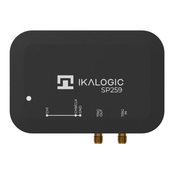
SP259 Series User Manual SP259 / SP259i Input power connector Micro USB 3.0 female Input current 200 mA Input voltage 0.5 V SP259(i) Interfaces SP259(i) logic analyzer ports and interfaces are shown in the diagram below: Figure 5: SP259i ports and interfaces 1. -
Page 12: Principle Of Operation
Principle of operation SP259 Series logic analyzers connects to a computer via a USB cable. A free so ware - called ScanaStu- dio - is used to configure the device and display captured signals. The so ware can also be used to further analyze the captured samples by decoding protocols like I2C, SPI or UART. -
Page 13: Flexitrig®Timing Performances
SP259 Series User Manual SP259 / SP259i • A or B (whoever triggers first) Finally, an external trigger output is always active, in all modes and generates a trigger pulse whenever a trigger condition is met and a capture starts. Signal specifications for External trigger input and output are detailed in the following section. -
Page 14: External Trigger In Specifications
SP259 Series User Manual SP259 / SP259i 10 ns delay (T1) between internal trigger detection and Trig Out assertion. Therefore, the total time for an external event to generate a Trigger OUT pulse is T0+T1 = 30ns. External trigger IN specifications Figure 7: External trigger IN timings The Trig In port allows to start acquisition on an external event generated by another instrument. -
Page 15: Rs485 Receiver Specifications
SP259 Series User Manual SP259 / SP259i • CAN bus receiver • 2x RS485 bus receivers (can be combined to form a full duplex RS422 bus receiver) • 2x RS232 receivers • LIN bus receiver Please refer to the marking on SP259i casing for exact pinout. -
Page 16: Lin Receiver Specifications
SP259 Series User Manual SP259 / SP259i Max. baudrate 8 Mbps Common Mode Operating range 12 V Common Mode Input Impedance 6 to 50 kΩ|| 20pF Common Mode Absolute max voltage 24 V Di erential Mode Operating range -4 V to +9 V... -
Page 17: What's In The Box
Device powered up, and detecting activity on one of the logic channels. So ware Quick Start guide Start by downloading the latest version of ScanaStudio so ware www.ikalogic.com and following instructions to install both so ware and provided drivers. It is recommended to restart your computer a er the so ware and drivers have been installed. -
Page 18: Capturing Your First Signal
You can adjust the capture duration by adjusting the number of samples in the device configuration tab. Mechanical data All SP259 series devices casing are manufactured from anodized aluminum, able to withstand heavy duty usage in various harsh environments. All markings are laser engraved, ensuring important pinout information is not lost over time. -
Page 19: Model Sp259I
SP259 Series User Manual SP259 / SP259i Model SP259i Weight: 95 gm Figure 8: SP259i dimensions (mm) Note: Dimensions are down with provided industrial terminal blocs, but they can be individualy detached and replaced by other compatible connectors. (c) Ikalogic SAS 2023... -
Page 20: Model Sp259
SP259 Series User Manual SP259 / SP259i Model SP259 Weight: 80 g Figure 9: SP259 dimensions (mm) (c) Ikalogic SAS 2023 20/26... -
Page 21: Probes
SP259 Series User Manual SP259 / SP259i Probes Probes cables are made of 24AWG flexible wires. All wires are black colored, but every wire has a white marking tube with the channel number (e.g. “1” or “GND”). 225±10 [mm] Figure 10: Probes dimensions (mm) -
Page 22: So Ware Technical Requirements
SP259 Series User Manual SP259 / SP259i So ware technical requirements Download ScanaStudio so ware on www.ikalogic.com so you can use your device on your favorite platform. SP259(i) and ScanaStudio were tested to supports the following platforms: • Windows 7/8/10 •... - Page 23 SP259 Series User Manual SP259 / SP259i in a particular installation. If this equipment does cause harmful interference to radio or television reception which can be determined by turning the equipment o and on, the user is encouraged to try to correct the interference by one or more of the following measures: •...
-
Page 24: Safety Information
SP259 Series User Manual SP259 / SP259i Safety information This product complies with safety standards IEC NF/EN 61010-1: 2010, IEC NF/EN 61010-2-030 and UL 61010-1: 2015 To prevent possible electrical shock, fire, personal injury, or damage to the product, read all safety information before you use the product. The following international symbols are used on the product and in this manual. -
Page 25: Limited Warranty & Limitation Of Liability
This warranty extends only to the original buyer or end-user customer of an Ikalogic authorized reseller, and does not apply to fuses, disposable batteries or to any product which, in Ikalogic’s opinion, has been misused, altered, neglected or damaged by accident or abnormal conditions of operation or handling. -
Page 26: Document Revisions
EXPRESS OR IMPLIED, INCLUDING BUT NOT LIMITED TO ANY IMPLIED WARRANTY OF MERCHANTABILITY OR FITNESS FOR A PARTICULAR PURPOSE. IKALOGIC SHALL NOT BE LIABLE FOR ANY SPECIAL, INDIRECT, INCIDENTAL OR CONSEQUENTIAL DAMAGES OR LOSSES, INCLUDING LOSS OF DATA, WHETHER ARISING FROM BREACH OF WARRANTY OR BASED ON CONTRACT, TORT, RELIANCE OR ANY OTHER THEORY.
Need help?
Do you have a question about the SP259 Series and is the answer not in the manual?
Questions and answers