Table of Contents
Advertisement
Quick Links
Advertisement
Table of Contents

Related Manuals for AGICO PUMA


Summary of Contents for AGICO PUMA
- Page 1 PUMA IMPULSE MAGNETIZER User Manual Version 1.0.0 April 2023...
-
Page 3: Table Of Contents
PUMA – User Manual Contents Contents PUMA Introduction Principle of operation ....... . . - Page 4 PUMA – User Manual User Manual Conventions User Manual Conventions Prohibition symbol is used to prohibit any action which may cause a loss of properties, damage or injury. Warning symbol is used to draw a special attention to an important infor- mation.
- Page 5 PUMA – User Manual General Safety Instructions General Safety Instructions Before operating the instrument, review the following safety precautions to avoid injury and prevent damage to this product or any products connected to it. Service procedures should be performed by qualified personnel only!
- Page 6 OFF the instrument or burning inner fuses. Dispose of packaging material immediately according to locally applica- ble regulations. However, it is recommended to keep the shipping box and inner foams in case of necessity to send the instrument to AGICO for repair.
- Page 7 PUMA – User Manual General Safety Instructions Storage and Transportation The properly wrapped instrument can be stored and transported at a tempera- ◦ ◦ ture -20 C to + 55 C and relative humidity up to 80 %. The instrument must be stored at suitable place, free of dust and chemical evaporation.
-
Page 9: Puma Introduction
PUMA Introduction 1 PUMA Introduction The PUMA is designed as a precise high field impulse magnetizer. Inner diame- ter of magnetization coil is 41 mm which allows to magnetize standard-sized pa- leomagnetic specimens in any orientation. PUMA enables to impart isothermal remanent magnetization (IRM) to specimens in the wide range of intensities of magnetic fields from 1 mT up to 5 T. -
Page 10: Instrument Description
PUMA – User Manual Instrument description 1.2 Instrument description 1.2.1 Technical parameters • Dimensions: width×height×depth: 715×435×500 mm (28.2×17.1×19.7 inch). • Mass: 78 kg (172 lbs). • Power requirements: 230 V, 10 A or 100-115 V, 20 A • Magnetic field intensity range: 1–5000 mT. -
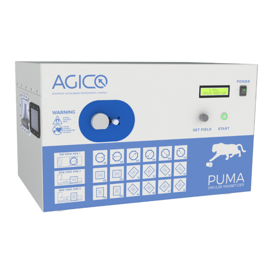
Page 11: Front And Back Panel
Sockets for the power cord and USB-B cable are located on the rear panel. Figure 3: Front panel of the PUMA Impulse Magnetizer 1.2.3 Coil cooling Magnetization coil temperature increases during the high intensity pulses, espe- cially if field is higher than 2 T. -
Page 12: Installation Of The Instrument
60x60 cm. Make sure that the fan outlets on the back and left side of the PUMA are clear. Maintain a distance of at least 15 cm between the fan outlets and any obstruction to allow sufficient air circulation and to ensure adequate cooling of the magnetizing coil. -
Page 13: Instrument Operation
PUMA – User Manual Instrument operation 2 Instrument operation 2.1 Specimen handling 2.1.1 Cylindrical specimen Two cylindrical specimen holders are supplied with the instrument, see Fig. 4. Figure 4: Cylindrical specimen holders Figure 5: Proper orientation of the cylindrical specimen inside the shell •... -
Page 14: Cubic Specimen
PUMA – User Manual Specimen handling 2.1.2 Cubic specimen Two holders for cubic specimens differ only in their dimensions – 20 or 23 mm cubes, see Fig. 6. The positioning of the specimen with respect to the 18 direction design is shown in Fig. 9 Figure 6: Cubic specimen holder 2.1.3 Holder Insertion... - Page 15 PUMA – User Manual Specimen handling Principal User mode A-mode B-mode C-mode D-mode P-mode Direction axes +x-axis 180/0 –x-axis 90/0 +y-axis 270/0 –y-axis 0/90 +z-axis 0/–90 –z-axis 45/0 225/0 315/0 135/0 90/45 270/–45 90/–45 270/45 0/45 180/–45 180/45 0/–45 Table 1: A scheme of eighteen magnetizing directions with a reference to the magne- tizing modes necessary to measure the anisotropy of isothermal magnetic remanence.
- Page 16 PUMA – User Manual Specimen handling Figure 8: 18 orientations of the cylindrical specimen...
- Page 17 PUMA – User Manual Specimen handling Figure 9: 18 orientations of the cubic specimen...
-
Page 18: Specimen Magnetization
Specimen magnetization 2.2 Specimen magnetization PUMA can be operated directly in the local mode or in remote mode using a PC connected via USB, which brings additional user comfort as well as possibility of more detailed setting of the pulse intensity. Sharing of the set and measured value of the magnetization field with REMA6 software, if running simultaneously on the same PC, is another benefit. -
Page 19: Remote Mode
PUMA is connected via COM4 and firmware version is 1.0 released on March 2023. Press to return to main screen. The unsuccessful activation result is shown in Fig. 12B, in this case check if the PUMA is switched on and USB cable is properly connected and the press to try again. - Page 20 PUMA – User Manual Specimen magnetization Figure 11: The main screen of the PUMA software. Figure 12: The activation window of the PUMA software. a) successful activation, b) unsuccessful activation of the instrument.
- Page 21 (see Fig. 11). In the case of some malfunction, PUMA returns an error message which is shown by PUMA software as well as visualized on the PUMA display. See section 3.2 for a list of error messages with suggestions for their...
-
Page 22: Troubleshooting
Troubleshooting 3 Troubleshooting PUMA Impulse magnetizer contains plenty of hardware control circuits and soft- ware diagnostic tests to prevent any serious damage to the device. Some potential errors and their solution are listed bellow. The best way to solve the problems with AGICO devices is to contact the manufacturer via email address agico@agico.cz. -
Page 23: Software Error Messages
3.3 Fuses The back panel of the PUMA contains two fuses with ratings T10 A / 250 V (230 V version) or T20 A / 250 V (100–115 V version) . T stands for time lag (slow-burn) fuse, 10 A or 20 A indicates maximum current of fuses and 250 V indicates maximum voltage.
Need help?
Do you have a question about the PUMA and is the answer not in the manual?
Questions and answers