Advertisement
Quick Links
NOTICE
*Please make sure that you have all parts indicated and they are in good condi�on before you
begin assembly of this item. Refer to part list and hardware list below for guidance.
*This item should be assembled on a so� surface to prevent scratching the finish during
assembly.
*This item may require periodic �ghtening.
*If you are having difficulty, our friendly Customer Care team is always here to help. Please
email customersupport@safavieh.com
PREPARATION
*Before beginning assembly of product, make sure all parts are present. Compare parts with
part contents list and hardware contents list.
*If any part is missing or damaged, do not a�empt to assemble the product.
*Es�mated Assembly Time: 60 minutes.
*Tools Required for Assembly (included): Allen Key
CARE AND MAINTENANCE
Always use felt pads under all ar�cles to prevent discolorra�on or so�tening of the lacquer.
Plas�c and rubber bases on items can discolor wood. Wipe up spills immediately and avoid
common hazards such as hot dishes, harsh solvents and abrasives. Cleaning should be done
with a so� lint free co�on cloth dampened with water or furniture polish. On highly used surfaces
we recommend applying a quality paste wax shich should be used on a reguler basis to provide
addi�onal protec�on from scratches and spills. How o�en you apply the wax depends on how
much wear the furniture receives.
Part List
P
N
O
M
Q
N
P
L
Q
C
R
P
N
O
G
F
K
G
Q
O
A
S
H
H
D
R
J
I
I
B
E
G
F
G
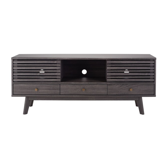
Model# MED9613
Product Dimensions: 59"Wx15"Dx24"H
This product is intended for use with a
Death or serious injury may occur
FLAT SCREEN TV ONLY
Maximum Screen Size: 65 inches
and/or video equipment furniture.
Weight Limit: 81.5 Ibs
A remote control or toys placed on
Shelf Load Limit: 22 Ibs
Drawer Load Limit: 17.6 Ibs
child to climb on the furnishing and
Use with heavier televisions may result
in instability causing tip over resulting in
death or Serious injury.
when children climb on audio
the furnishing may encourage a
as a result the furnishing may tip
over on the child.
Advertisement

Related Manuals for Safavieh Furniture MED9613


Summary of Contents for Safavieh Furniture MED9613
- Page 1 *If you are having difficulty, our friendly Customer Care team is always here to help. Please email customersupport@safavieh.com PREPARATION Model# MED9613 *Before beginning assembly of product, make sure all parts are present. Compare parts with part contents list and hardware contents list.
-
Page 2: Hardware List
Hardware List HW1x24 HW2x12 HW3x26 HW4x10 HW5x26 HW6x8 Ø 8 x 30 mm M 7 x 50 mm Ø 6 x 35 mm Ø 15 mm M 6.4 x 53 mm HW7x2 HW8x26 HW9x12 HW10x18 HW11x6 HW12x1 M 6 x 10.5 mm Ø... - Page 3 Part List & HW For Mul�-Box Items Piece Descrip�on Carton Call Piece Descrip�on Carton Call Top Board 1 of 1 Cambolt 1 of 1 1 of 1 1 of 1 Bo�om Board CamLock Big Side Board Le� 1 of 1 1 of 1 Dowel Medium Side Board Right...
- Page 4 PREPARATION Before beginning assembly of product, make sure all parts are present. Compare parts with part contents list and hardware contents list. If any part is missing or damaged, do not a�empt to assemble the product. Es�mated Assembly Time: 60 minutes. Name Plate STEP1: Insert Cambolt (HW1) into Front Drawer Right (K), STEP2: Combine Side Drawers (N &...
- Page 5 50 - 60 mm RM30A RM30A RM30A STEP5:Install the metal runner (HW RM30A) into posi�on STEP6: Insert the Screw M3.5x15.5mm (HW14) and wedge (HW5) as shown in picture. into the bo�om of the drawer according to the picture. Secure with screws M3.5x13mm (HW10). Warning Label STEP8: Insert Cambolt (HW1)into Top Board (A).
- Page 6 RM30A RM30A RM30A RM30A Laminated Edge Laminated Edge STEP9: Insert Dowel Medium (HW3) into Side Board Le� (C) and STEP10: Part of Metal Runner must be installed to Center Board small (I) on both sides. Side Board Right (D). Secure part of the metal runner (HW RM30A) into posi�on as the above image, Insert Camlock (HW1) into Side Board Le�...
- Page 7 Front STEP14: Bring the Top Board (A) into assembled component. STEP13: A�ach Center Board small (I) into the assembled component Secure with Camlock Big (HW2) and �ghten it using screwdriver. from step 12. Insert Cambolt (HW1), Camlock Big (HW2) and �ghten it using screwdriver.
- Page 8 ±2 mm ±2 mm STEP18: Combine the Support Leg 2(F) from step 17 with STEP17: Combine components from step 16 with remaining Support Leg 1 (E), using Screw M4x16mm (HW20). remaining Support Leg 1 (E), using Screw M4x16mm (HW20). Do not over�ght screw yet, leave around 2mm gap. Do not over�ght screw yet,leave around 2mm gap.
- Page 9 Fixing The Legs Tighten all screws on corner bracket STEP22: Insert Screw M6.4x53mm (HW4) into posi�on. �ghten screws using Allen Key (HW7). STEP21: Remove plas�c cap from Legs. Insert the bolt of the Leg (G) into hole of corner brace(HW BC410) as shown in figure. Insert Flange Nut (HW15) first into the hanger bolt of leg, �ghten all the nuts using provided Wrench (HW12).
- Page 10 STEP26: Peel the back paper of Bumper (HW23) then 2 pcs on Frame Door Le�, 1 pc on Frame Door Right, posi�on as shown STEP25: Insert Pin Sliding Top (HW21) and Pin Sliding Bo�om (HW22) in the figure. on both end of frame door as specified posi�on in the figure. Hold the frame door with posi�on of the upper pin shown in facing upward.
- Page 11 TIPPING RESTRAINTS KIT INSTALLATION GUIDANCE Different wall materials require unique wall fasteners. The wall plugs (AA2) and screws (AA3) are designed for fixing to concrete walls only. Please consult your local hardware store to ensure you are using the correct hardware for your wall type. AA1 x 2 AA2 x 4 AA3 x 4...
Need help?
Do you have a question about the MED9613 and is the answer not in the manual?
Questions and answers