Table of Contents
Advertisement
Quick Links
1. Introduction........................................ ...............................................................1
2. System Diagram........................... ....................................................................2
3. System Operation .............................................................................................3
4. Installation Procedure .......................................................................................4
5. Specifications ...................................................................................................6
6. Mechanical Drawings .......................................................................................6
1. Introduction
The InPower Ambulance Module Power Disconnect Switch is intended for use in ambulances to disconnect battery
power from module loads, such as emergency lights, patient compartment lights, floodlights and loading lights. The
module contains a high current solid state contactor (power switch), a current sensor and a microprocessor control and
monitor circuit. Its over-current shutdown rating is 275 amps with a surge rating of 800 amps, and it provides automatic
fault shutdown for over current and loss of ground. The standard model described in this manual is SSC42-275, but
many custom programs are available. Please call us for more information.
Five control inputs offer a variety of different control configurations, including up to three time delayed power shut-off
modes. Input A allows instant shut-off, Inputs B, C and D offer time delayed shut-off modes, and Input E cancels all
timed shut-offs.
An amber LED indicator displays the power switch status. It illuminates any time the power switch is on, and it flashes
when switch is on and the timer is running in a timed shut-off mode. The LED blinks at a fast rate to indicate a fault shut
down condition.
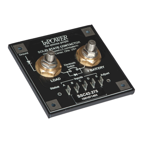
The DC power terminations are two 3/8 - 16 threaded studs with brass contact pads. The five control inputs are 0.25
inch male faston blade terminals. The four mounting holes provide the required connection to ground.
oad Considerations: Relays/Solenoids on the output must incorporate Fly Back Suppression Diodes/Circuitry.
L
These Relays/Solenoids (without suppression) can create large voltage and current spikes which damage electron-
ics. Having inductive loads without suppression violates your unit's warranty and may damage your vehicles elec-
tronics!
Electrical System Solutions
© Copyright 2023 InPower LLC
OWNERS MANUAL
InPower Model SSC42-275
Ambulance Module Power Disconnect Switch
with One On/Off and Three Time Delayed Shutoff Modes
InPower LLC
8311 Green Meadows Drive
Lewis Center, Ohio 43035
740-548-0965
www.InPowerLLC.com
SSC42-275 Owners Manual
Page
1 of 6
Document: OM-85
Date: October 30, 2008
Version Code: F
Date: May 24, 2023
Advertisement
Table of Contents

Related Manuals for InPOWER SSC42-275

Summary of Contents for InPOWER SSC42-275
- Page 1 Its over-current shutdown rating is 275 amps with a surge rating of 800 amps, and it provides automatic fault shutdown for over current and loss of ground. The standard model described in this manual is SSC42-275, but many custom programs are available. Please call us for more information.
- Page 2 Input B and Input C: Operation: Momentarily pressing control switch to Operation - SSC42-275 & SSC42-275-SPC43: position A once will turn on module power Control switch to On turns on module power. for a fixed 5 minute period. Pressing it twice Control switch to Off starts adjustable timer.
- Page 3 3. System Operation 3.1 Electronic Power Switch The SSC42-275 module power disconnect switch is 100% electronic. When activated, it connects the LOAD terminal to the +BATTERY terminal, delivering power to the module’s 12 Vdc loads. The highly efficient power switch has a very low on-resistance, resulting in a very low voltage drop and low internal heat dissipation. As many DC loads are inductive, the power switch contains an internal clamping diode between its LOAD terminal and ground.
- Page 4 4. Installation Procedures This section provides instructions for installing the InPower Model SSC42-275 Ambulance Module Power Disconnect Switch. It is important that you follow these instructions carefully and contact InPower if you need assistance or more information. 4.1 Safety Precautions...
- Page 5 Ground Note: The Mounting Surface provides a means to remove heat generated by the SSC42-275. If this surface is a poor conductor of heat, the disconnect switch will have a lower current rating than if the surface is a good...
- Page 6 InPower LLC SSC42-275 Owners Manual Page 8311 Green Meadows Drive 6 of 6 Document: OM-85 Version Code: F Lewis Center, Ohio 43035 Electrical System Solutions 740-548-0965 Date: October 30, 2008 Date: May 24, 2023 © Copyright 2023 InPower LLC www.InPowerLLC.com...
Need help?
Do you have a question about the SSC42-275 and is the answer not in the manual?
Questions and answers