
Related Manuals for Allen-Bradley Dataliner DL40 Plus

Summary of Contents for Allen-Bradley Dataliner DL40 Plus
- Page 2 Allen-Bradley publication SGI-1.1, Safety Guidelines for the Application, Installation and Maintenance of Solid-State Control (available from your local Allen-Bradley office), describes some important differences between solid-state equipment and electromechanical devices that should be taken into consideration when applying products such as those described in this publication.
- Page 4 Publication 2706-6.3...
- Page 5 Table of Contents toc–ii Publication 2706-6.3...
- Page 6 Table of Contents toc–iii Publication 2706-6.3...
- Page 7 Table of Contents toc–iv Publication 2706-6.3...
- Page 8 Read this chapter to familiarize yourself with the rest of the Dataliner DL40 Plus Slave Message Display manual. You will learn about: • contents of this manual • intended audience • conventions used • related publications This manual describes how to install and use your DL40 Plus Slave display.
- Page 9 “B7 hex”. You may need to refer to the following related publications: Publication Publication Title Description Number Dataliner DL40 Plus Message Provides installation, wiring and 2706-6.1 Display User Manual operating instructions for the DL40 Plus display (not slave display). Also describes use of the onboard message editor.
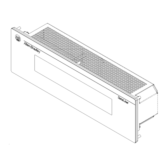
- Page 10 This chapter describes the DL40 Plus Slave display and summarizes its capabilities. The following topics are included in this chapter: • DL40 Plus Slave description • Operating modes • Features • Typical configurations The DL40 Plus Slave displays are available in two-line and four-line versions.
- Page 11 Introduction to the DL40 Plus Slave The DL40 Plus Slave has four operating modes: • DL Slave • PV Slave • Terminal • Diagnostic DL (Dataliner) Slave Mode Use this mode when connecting the DL40 Plus Slave to a DL40 Plus master display or an enhanced PanelView terminal such as the PV1400e.
- Page 12 Introduction to the DL40 Plus Slave DL40 Plus Slave displays have these features: DL40 Plus 5 x 7 Dot Matrix Characters Two or Four-Line Vacuum Fluorescent Display DIP Switch Configuration Operates on standard RS-485 Port 100 - 240V AC, 50/60 Hz 12V DC Supply for Relay Connections Relay with N.O.
- Page 13 Introduction to the DL40 Plus Slave Here are some of the most typical applications: DL40 Plus to DL40 Plus Slave Other Slaves DL40 Plus Slave SYSTEM CHECK NORMAL DL40 Plus (Master) RS-485(multidrop) RS-485(multidrop) PRESS #1 STOPPED RS-232 (point-to-point) DL40 Plus Slave CHECK PRESS #1 Other Slaves Host Controller or Personal Computer...
- Page 14 This chapter describes how to configure the DL40 Plus Slave display using the configuration DIP switches. The following topics are provided: • DIP switch location • Selecting the operating mode • Selecting display language • Setting the baud rate • Selecting display/communication options •...
- Page 15 Setting the DIP Switches The DL40 Plus Slave display operates in one of four modes. Chapter 1 briefly describes these modes. For detailed descriptions refer to the individual chapters describing each mode. Select the mode using Mode (DL Slaves Setting) position #1 and #2 of DIP Switch #1.
- Page 16 Setting the DIP Switches Positions #7 and #8 determine the parity, set the parity to match the host device. Positions #9 and #10 apply to Terminal mode operation, Cursor & Refer to Chapter 6. Auto New Line Even Parity Enabled Disabled Position # Condition...
- Page 17 Setting the DIP Switches Publication 2706-6.3...
- Page 18 This chapter describes how to mount and make electrical connections to the DL40 Plus Slave display. The following topics are described: • Mounting Instructions • Panel Cutout Dimensions • RS-232 Connections • RS-485 Connections • Relay Connections • Power Connections •...
- Page 19 Installation and Startup All dimensions are in inches (millimeters) Cutout 13.62 (345.9) 6.81 (173.0) 0.19 (4.8) Cutout 3.88 3.50 (98.4) (88.9) 0.19 (4.8) 6.94 (176.1) 0.25 (6.4) Diameter Hole 6 places 13.87 (352.3) Cutout 13.62 (345.9) 6.81 (173.0) 0.19 (4.8) Cutout 5.68 5.30...
- Page 20 Installation and Startup 13.16 (334.2) 4.38 (111.3) 14.357 (365.0) 3.16 (80.3) 3.19 Dimensions are in inches (millimeters) (81.0) 6.16 (156.4) 13.16 (334.2) 14.357 (365.0) 3.16 (80.3) Dimensions are in inches (millimeters) 3.19 (81.0) Publication 2706-6.3...
- Page 21 Installation and Startup Install the DL40 Plus Slave display conforming to NFPA 70E, Electrical Safety Requirements for Employee Workplaces. In addition to the NFPA general guidelines, refer to the following: Careful cable routing helps minimize electrical noise. Route incoming power to the module by a separate path from the communication cables.
- Page 22 Installation and Startup Use the RS-232 port to connect the DL40 Plus Slave to: • DL40 Plus Master • PanelView Printer Port • 1771 or 1746-DB BASIC Module • PLC-5 Channel 0 • SLC Channel 0 The following figure shows the location and terminal definitions for the RS-232 port.
- Page 23 Installation and Startup Connect the DL40 Plus Slave to a PanelView RS-232 printer port as shown below. The PanelView sends messages to the DL40 using its print messages function. You can also use the DTAM Plus programming cable (Catalog No. 2707-NC2) with a male-female pin adapter.
- Page 24 Installation and Startup Connect the DL40 Plus Slave to a PLC-5 Channel 0 port as shown below. You can also use programming cable (Catalog No. 2706- NC12). PLC-5 Channel 0 DL40 Plus Slave 25 Pin D Shell Connector RS-232 Port No Connection No Connection Common...
- Page 25 Installation and Startup Use the RS-485 port to connect the DL40 Plus Slave to: • DL40 Plus Master • Personal Computer using an RS-485 Converter The following figure shows the location and terminal definitions for the RS-485 port. DL40 Plus Slave RS-485 Pin # Function...
- Page 26 Installation and Startup One or multiple DL40 Plus Slave displays may be connected to a single DL40 Plus master display using the RS-485 port. The RS-485 network supports multi-drop communications with up to 126 slave displays. Use Belden 9842 cable at a maximum length of 4,000 ft (1219 meters).
- Page 27 3-10 Installation and Startup If you are using a personal computer to send messages to the DL40 Plus Slave using the RS485 port, refer to the following diagram: DL40-Plus Slave RS-485 Converter Box Display- RS-485 Port (Model LD-485A-MP) T e r m R X B C H - B Monitor...
- Page 28 3-11 Installation and Startup Use the DL40 plus slave relay to trigger a remote alarm or warning light. The relay has contacts rated at 3A at 250V AC. Connect the remote alarm or light to the relay connectors on the back of the DL40 Plus Slave.
- Page 29 3-12 Installation and Startup Before making power connections, make sure that the power is turned off. The DL40 Plus Slave requires 100-240Volts AC, 50/60 Hz, 0.60 - 0.25 Amperes. ATTENTION: Improper wiring of the power connections may result in damage to the DL40. White Black (Blue)
- Page 30 3-13 Installation and Startup When power is applied to the DL40 Plus Slave a powerup sequence of displays are shown. The first display on powerup is the sign-on banner identifying the hardware and firmware: DL40 PLUS SLAVE 2L VER 1.00 (10/16/98) Following the sign-on banner, all of the display pixels are turned on for 2 seconds followed by a series of informational messages...
- Page 31 3-14 Installation and Startup Publication 2706-6.3...
- Page 32 This chapter describes the operation of the DL40 Plus Slave in DL Slave Mode. This chapter contains the following topics: • Slave mode description • Slave mode protocol • Example messages • Display options • Clearing one or more lines •...
- Page 33 Dataliner (DL) Slave Mode Messages sent to the DL40 Plus Slave in DL Slave mode must have the following format: 20 Characters Slave Line Carriage to Display Address Number Return If you are using a DL40 Plus as the master, configure its communication port for DL Slaves (refer to the DL40 Plus user manual, Publication 2706-6.1).
- Page 34 Dataliner (DL) Slave Mode For example, a print statement for a Catalog No. 1771-DB Basic module with a DL40 Plus Slave display would be: Carriage Return Slave 1 Line 1 100 PRINT #”VALVE NUMBER 1 OPEN”, CHR(1), CHR(1), CHR(13) The message VALVE NUMBER 1 OPEN would be displayed on line one of slave number one.
- Page 35 Dataliner (DL) Slave Mode To clear one or more lines on a DL40 Plus Slave, use: Slave Line Carriage Address Number Return The following table lists the line number byte required for clearing any or all lines of the display. Use this Byte for Line Number: To Clear: ASCII...
- Page 36 This chapter describes the operation of the DL40 Plus Slave in the PV Mode. The following topics are described: • PV Slave Mode description • PV Mode protocol • Display options Use the PanelView (PV) Slave Mode to send the DL40 Plus Slave messages from a PanelView operator terminal.
- Page 37 PanelView (PV) Slave Mode Use the following control codes to control the appearance of messages displayed in PV Mode. [Ctrl][F] $ DAN Flash code. Send the [Ctrl][F] command when you want the display characters to flash. All characters following the first flash code in a message flash.
- Page 38 PanelView (PV) Slave Mode The PanelView Slave mode has two special display characteristics that make messages easier to read: Line to Line Delay After each individual line is displayed, there is a one second pause before the next line is displayed. This delay provides time for each line to be read.
- Page 39 PanelView (PV) Slave Mode Publication 2706-6.3...
- Page 40 This chapter describes the operation of the DL40 Plus Slave in Terminal Mode. This chapter contains the following topics: • Terminal mode operation • Protocol Terminal mode allows more control over messages than the basic Slave Mode setting. In terminal mode, you can control: •...
- Page 41 Terminal Mode Message text and control codes are sent serially to the DL40 Plus Slave in terminal mode. The following control codes are used: Cursor Up (Ctrl-K ) (0B hex) Positions the cursor directly above the current cursor position. If the cursor is on the first line, the cursor is moved to the last line on the display.
- Page 42 Terminal Mode New Line (Ctrl-_) (1F hex) Moves the cursor to the beginning of the line below. If the cursor is on the last line, every line is moved up one line and the bottom line is cleared. Delete Line (Esc and then (1B, 52 hex) Clears the current line.
- Page 43 Terminal Mode Set Flashing Mode (ESC G 2) (1B, 47, 32 hex) Enables flashing text mode. All characters received after this command are displayed flashing until disabled with a Clear Flashing Mode command. Clear Flashing Mode (ESC G 0) (1B, 47, 30 hex) Disables flashing text mode.
- Page 44 This chapter describes the operation of the DL40 Plus Slave in the Diagnostic Mode. Use the diagnostic mode to verify communications with a host device. Diagnostic mode displays the exact data being sent by a host device. Use the diagnostic mode as a temporary installation and troubleshooting aid.
- Page 45 Diagnostic Mode Data Errors If the DL40 Plus Slave and host are not set to the same serial port settings, a reception error occurs. The error symbol is a ! displayed as the last character on line 1. This symbol is displayed for 1/5 sec (200 msec) after each serial error.
- Page 46 Character Height Two line display 11.3 mm (0.44 inch) Four line display 11.3 mm (0.44 inch) Character Set English Standard & Extended ASCII Characters Cyrillic Standard & Cyrillic (Russian) Characters International Standard & International ISO 8859-1 Characters Characters per Display Line 7.6 meters (25 feet) Viewing Distance - Approximate Vacuum fluorescent, 5 x 7 dot matrix...
- Page 47 Specifications to 60 C (+32 to 140 ° ° ° ° Temperature Range - Operating to 85 C (-40 to 185 ° ° ° ° Temperature Range - Storage 5% to 95% (non-condensing) Humidity Operating 15G, Non-operating 30G pulses Shock Operating 1.0G, Non-operating 2.5G Vibration sinusoidal...
- Page 48 Publication 2706-6.3...
- Page 49 +D=H=?JAH 5AJI The following extended ASCII characters are available with all char- acter sets (English, International, and Cyrillic). Publication 2706-6.3...
- Page 50 +D=H=?JAH 5AJI The Cyrillic character set is enabled when position #3 is On and position # 4 is Off on DIP Switch 1. Publication 2706-6.3...
- Page 51 +D=H=?JAH 5AJI The International character set is enabled when position #3 is Off and position # 4 is On (DIP Switch 1). Publication 2706-6.3...
- Page 52 )@@HAII )@@HAII " " Publication 2706-6.3...
- Page 53 Slave Address Settings Address Address Publication 2706-6.3...
- Page 54 This program assumes that the message text is entered in the string file ST30:10. This file contains the message text and defines the slave number and line number the mesage is to be displayed on. Refer to page 4-3 for an example message. PLC-5 Channel 0 to Dataliner DL40 Slave in DL Slave Mode, PLC-5 in User-Mode Timer On Delay...
- Page 55 SLC/PLC Program Examples Channel 0 of SLC connected to DL40 Slave operating in DL Slave mode. This timer is used to continuously send ASCII data to the DL40 slave display. Timer On Delay 0000 Timer T4:0 Time Base Preset 4< Accum 0<...
- Page 56 Publication 2706-6.3...
- Page 57 Index Publication 2706-6.3...
- Page 58 Index Publication 2706-6.3...
- Page 59 1`" Index Publication 2706-6.3...
- Page 60 Publication 2706-6.3 - December 1998 41061-096-01(A) © (1998) Rockwell International Corporation. Printed in the U.S.A.
Need help?
Do you have a question about the Dataliner DL40 Plus and is the answer not in the manual?
Questions and answers