Floodstop FS34NPT, FS12NPT, FS14C, FS3/8C, FS1NPT, FS125NPT - Automatic Water Shut-off System Manual
- Installation and operating manual (6 pages)
Advertisement
Introduction
This product has been designed to give you years of reliable service and minimize home water damage by detecting water leaks and automatically shutting off the water supply.
To ensure proper installation and to maximize the performance of your Floodstop water leak detection system, please read this manual thoroughly.
PLEASE READ CAREFULLY BEFORE PROCEEDING: If a leak is detected, the Floodstop Valves will shut off the water going to the washing machine. This will stop the continuous flow of water from the water supply valve to the water heater. However, all or some of the water that is already in the water heater and hoses may still leak out onto the floor.
NOTE: This unit was shipped with an installation and operating manual that contains important information about its operation. If you are installing this unit for use by others, we recommend you leave this manual – or a copy of it – with the user.
FEATURES
Water Heater Kit – Model FS3/4NPT
- Control Panel has easy to read, lighted function buttons
- AC Power with battery backup – For continued operation in the event of power outages
- Solid brass, full port motorized ball valves for dependable, long lasting performance
- Valves automatically shut-off the water supply when a leak is detected
- Automatic monthly maintenance cycling of the valves to ensure reliable operation
- Valves can be opened and closed with the touch of a button
- Activates an audible alarm when a leak is detected
- Mute button to silence the audible alarm
- Can be reset and reused continuously with the touch of a button
- Can be tested at any time with the touch of a button
- Can accommodate additional water leak sensors
- 1 Year Limited Warranty
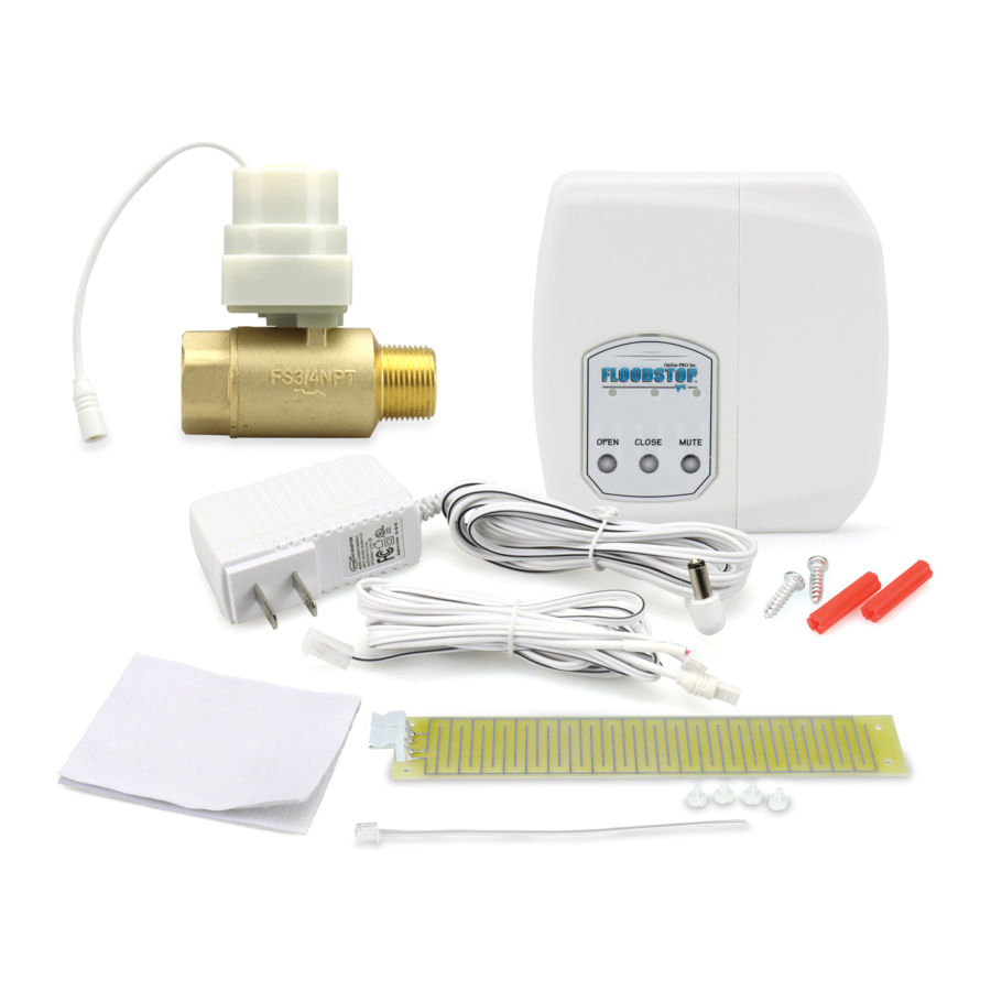
This Package Contains

- (1) Floodstop Motorized Brass Valves (3/4" FIP x 3/4" MIP)
- (1) Control Panel
- (1) Leak Sensor with Paper Sleeve
- (1) AC Adaptor
- (1) Wire Harness
- (1) Hook & Loop Mounting Pad
- (2) Mounting Screws with Anchors
- (1) Pigtail
Check to make sure everything in the package matches the Contents Listing above. Read the instructions thoroughly before installing or operating the Floodstop system.

Do not put finger(s) inside Floodstop Valves. Risk of serious injury may occur.

Do not grip plastic motor drive for leverage when tightening Floodstop Valves.
STOP: You may need to purchase additional fittings to install the Floodstop Valve to your existing water line. We recommend that you contact a licensed plumber.
- For use with water only.
- Do not install on gas line.
Installation
- Shut off main water supply valve.
Step 4 instructs you to install the Floodstop Valve (3/4" FIP x ¾" MIP) between the rigid water line coming off the manual cold water valve and the water heater. Most rigid lines will be copper. Evaluate your line and determine which size adapter fitting you will need (the most common one will be 3/4" solder x 3/4" MIP). Then determine what size union you will need between the Floodstop Valve and the water heater. Note that in some cases you can use a flexible or corrugated water heater connector in place of a union.

- Open faucet nearest water heater to relieve water pressure.

- Shut off the manual cold water valve that supplies water to the water heater. Note that the top of the water heater will usually be marked "Cold" or "Inlet" at the point where the cold water line is connected.

- Position the Floodstop Valve so that the arrow on the side of the valve is pointing to the water heater. Install the Floodstop Valve between the rigid water line coming from the manual cold water valve and the water heater.
NOTE: The Floodstop Valve should be installed within 2 feet of the water heater so that the Leak Sensor can lay flat on the floor.

- Mount the Floodstop Control Panel in an easily accessible location within 30 inches of the Floodstop Valves. You may mount the panel using the screws and anchors, or Hook & Loop Mounting Pad provided. When using the Hook & Loop Mounting Pad, make sure the adhesive is put on a clean, dry surface.
NOTE: Depending on the location you pick, and the distance between the hot and cold shut-off valves, you may need to purchase two (2) Floodstop Control Panel to Valve Extension Wires, Model #FSACEXT9 (available where you purchased your Floodstop System).

- With the contacts of the wire harness connector facing you, plug the 6-pin connector end of the Wire Harness into the bottom of the Control Panel.

- Take the 2 short wires coming from the Control Panel and connect each one to a Floodstop Valve (make sure the arrow on the side of the plugs line up with each other). It does not matter which wire gets connected to which Floodstop Valve.
NOTE: The Leak Sensor comes with a Paper Sleeve. If the Leak Sensor is going to make contact with the washing machine, or any other piece of metal, make sure you leave the Paper Sleeve on. If the Leak Sensor makes contact with metal, it will signal the Floodstop Valve to shut off. The Paper Sleeve acts as a barrier between the Leak Sensor and the metal. When the Paper Sleeve becomes wet, it will signal the Floodstop Valve to shut off. If the Leak Sensor will not be contacting metal, you may remove the Paper Sleeve.

- Connect plug on end of long flat wire coming from Control Panel to either set of prongs on the Leak Sensor, pushing until plug snaps in place. Then place Leak Sensor on the floor behind the washing machine.
NOTE: Additional Leak Sensors can be connected together for added protection. For additional Leak Sensors, purchase Floodstop Water Leak Sensor, Model #FSAXS01 (available where you purchased your Floodstop System).

![]()
Do not place Leak Sensor or cord in a walkway, or other location that may cause someone to trip and fall. - Plug the pin on the end of AC Adaptor cord into the bottom of the Control Panel, and then plug the AC Adaptor into a wall outlet. Green indicator lights will start to flash, showing you have power. Note that a red low battery indicator light will also flash about every 30 seconds, and the unit will beep once a minute until the batteries are installed.
NOTE: If a nearby wall outlet is not available you will need to purchase a thin low voltage Floodstop "AC Adaptor Extension Wire" Model #FSAWAE9 (available where you purchased your Floodstop System). This wire extends the length of the AC Adaptor cord.

![]()
Do not plug the AC Adaptor into an extension cord. - Floodstop has a battery backup system that allows the unit to continue working in the event that you have a power outage. To set up the backup system, open the front of the Control Panel and install 4 fresh AA alkaline batteries (batteries not included). The low battery indicator light will now stop flashing and the beep will stop.

![]()
Replace batteries once a year or sooner as necessary. If batteries need to be changed sooner, a red low battery indicator light will flash, and a beep will sound. - Shut off the previously opened faucet and turn on both valves that were shut off in steps 1 and 3. Check for leaks. Note that the green status light on the Control Panel will indicate whether the Floodstop Valve is open or closed.


How to Operate your Control Panel

- Left button opens Floodstop Valve
- Middle button closes Floodstop Valve
- Right button mutes the audible alarm that sounds when a leak is detected
Testing Your Device
- Push the Open button to make sure Floodstop Valve is open.
- When the Floodstop Valve is opening or closing, you will hear the valve motor operating for a few seconds.
- Saturate a rag with water and squeeze over Leak Sensor, or dip the Leak Sensor into a small bucket of water. Once the Leak Sensor is wet, it will signal the Floodstop Valve to close, then an audible alarm will sound and a red light will flash.
- Push the Mute button to silence the alarm. Note that the red light will continue to flash. This means the Floodstop Valve is closed and will remain closed until you push the Open button.
- Before the Floodstop Valve can be opened, the Leak Sensor needs to be dry. There is no need to unplug the unit when drying off the Leak Sensor.
- The water test can be done with the paper sleeve still on the Leak Sensor. Note that the paper sleeve is reusable, but once it gets wet you will need to let it air dry flat before placing it back on the Leak Sensor.
Pressure Drop Data
The maximum pressure drop for this device is 2 psi at a flow rate of 5.5 gpm for NPS-3/4 and larger.
Helpful Hints
- If the Leak Sensor Paper Sleeve is misplaced or becomes unusable, a paper towel can be used in its place.
- The Leak Sensor has two sets of prongs so you can connect additional Leak Sensors. You can link them together, so they are positioned at different locations around your laundry area.
- Once a month, the Floodstop Valves will automatically close and open by themselves. The Control Panel is programmed to run this cycle to ensure that the valves continue to function properly in the event that they need to shut off the water.
- Hanging Wires may be tied together using twist ties (Not provided).
Troubleshooting
| Problem | What to Check |
Status light does not light |
|
No water comes out of hot side of faucet |
|
Floodstop Valve does not operate |
|
The alarm goes off for no apparent reason |
|
Floodstop Valve does not operate |
|
Manual Operation of Floodstop Valve
- Unplug the connection between the Control Panel and the Floodstop Valve.
- Pull the plastic motor cover off the Floodstop Valve and slide it down the wire until it stops at the plug. Note that no tools are needed to remove the cover.
- Use a marker and draw a line across the top of the plastic motor housing. This way once the motor is removed you will know how to reposition it for assembly.
- Remove the 4 screws using a Phillips head screwdriver.
- Place thumb and finger on plastic gear and rotate clockwise to open valve or counter clockwise to close it. Do not use tools to manually open or close valve.
1 Year Limited Warranty
To obtain warranty service, call our Customer Service Department at 1-800-888-8312, or e-mail us at tncustserve@ipscorp.com.

Documents / ResourcesDownload manual
Here you can download full pdf version of manual, it may contain additional safety instructions, warranty information, FCC rules, etc.
Advertisement


Need help?
Do you have a question about the FS34NPT and is the answer not in the manual?
Questions and answers