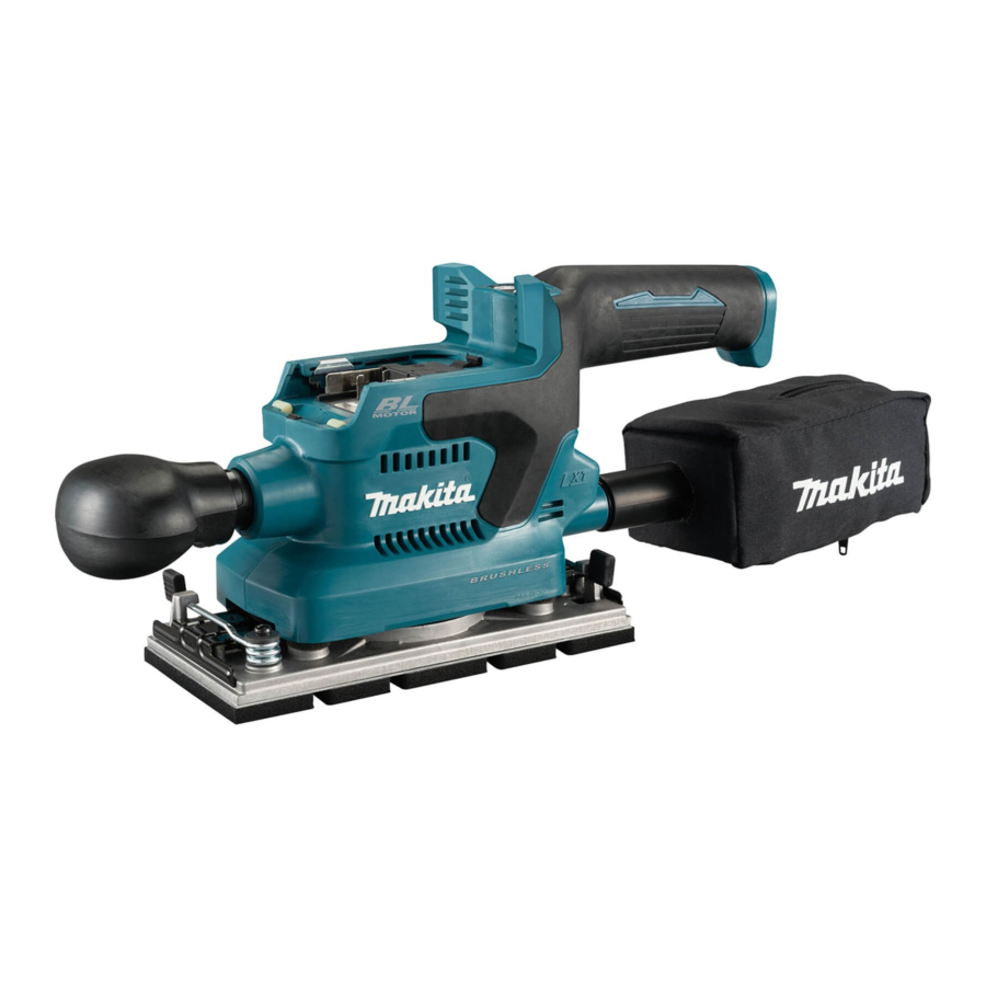
Makita DBO380, DBO381 - Cordless Finishing Sander Manual
- Instruction manual (128 pages) ,
- Instruction manual (128 pages) ,
- Instruction manual (105 pages)
Advertisement
SAFETY WARNINGS
General power tool safety warnings

Read all safety warnings, instructions, illustrations and specifications provided with this power tool. Failure to follow all instructions listed below may result in electric shock, fire and/or serious injury.
Save all warnings and instructions for future reference.
The term "power tool" in the warnings refers to your mains-operated (corded) power tool or battery-operated (cordless) power tool.
Sander safety warnings
- Always use safety glasses or goggles. Ordinary eye or sun glasses are NOT safety glasses.
- Hold the tool firmly.
- Do not leave the tool running. Operate the tool only when hand-held.
- This tool has not been waterproofed, so do not use water on the workpiece surface.
- Ventilate your work area adequately when you perform sanding operations.
- Some material contains chemicals which may be toxic. Take caution to prevent dust inhalation and skin contact. Follow material supplier safety data.
- Use of this tool to sand some products, paints and wood could expose user to dust containing hazardous substances. Use appropriate respiratory protection.
- Be sure that there are no cracks or breakage on the pad before use. Cracks or breakage may cause a personal injury.
- Watch your footing and maintain your balance with the tool. Make sure there is no one below when working in high locations.
SAVE THESE INSTRUCTIONS.
DO NOT let comfort or familiarity with product (gained from repeated use) replace strict adherence to safety rules for the subject product. MISUSE or failure to follow the safety rules stated in this instruction manual may cause serious personal injury.
Important safety instructions for battery cartridge
- Before using battery cartridge, read all instructions and cautionary markings on
- battery charger,
- battery, and
- product using battery.
- Do not disassemble or tamper with the battery cartridge. It may result in a fire, excessive heat, or explosion.
- If operating time has become excessively shorter, stop operating immediately. It may result in a risk of overheating, possible burns and even an explosion.
- If electrolyte gets into your eyes, rinse them out with clear water and seek medical attention right away. It may result in loss of your eyesight.
- Do not short the battery cartridge:
- Do not touch the terminals with any conductive material.
- Avoid storing battery cartridge in a container with other metal objects such as nails, coins, etc.
- Do not expose battery cartridge to water or rain.
A battery short can cause a large current flow, overheating, possible burns and even a breakdown.
- Do not store and use the tool and battery cartridge in locations where the temperature may reach or exceed 50°C (122°F).
- Do not incinerate the battery cartridge even if it is severely damaged or is completely worn out. The battery cartridge can explode in a fire.
- Do not nail, cut, crush, throw, drop the battery cartridge, or hit against a hard object to the battery cartridge. Such conduct may result in a fire, excessive heat, or explosion.
- Do not use a damaged battery.
- The contained lithium-ion batteries are subject to the Dangerous Goods Legislation requirements.
For commercial transports e.g. by third parties, forwarding agents, special requirement on packaging and labeling must be observed. For preparation of the item being shipped, consulting an expert for hazardous material is required. Please also observe possibly more detailed national regulations.
Tape or mask off open contacts and pack up the battery in such a manner that it cannot move around in the packaging. - When disposing the battery cartridge, remove it from the tool and dispose of it in a safe place. Follow your local regulations relating to disposal of battery.
- Use the batteries only with the products specified by Makita. Installing the batteries to non-compliant products may result in a fire, excessive heat, explosion, or leak of electrolyte.
- If the tool is not used for a long period of time, the battery must be removed from the tool.
- During and after use, the battery cartridge may take on heat which can cause burns or low temperature burns. Pay attention to the handling of hot battery cartridges.
- Do not touch the terminal of the tool immediately after use as it may get hot enough to cause burns.
- Do not allow chips, dust, or soil stuck into the terminals, holes, and grooves of the battery cartridge. It may result in poor performance or breakdown of the tool or battery cartridge.
- Unless the tool supports the use near high-voltage electrical power lines, do not use the battery cartridge near high-voltage electrical power lines. It may result in a malfunction or breakdown of the tool or battery cartridge.
- Keep the battery away from children.
SAVE THESE INSTRUCTIONS.

Only use genuine Makita batteries. Use of non-genuine Makita batteries, or batteries that have been altered, may result in the battery bursting causing fires, personal injury and damage. It will also void the Makita warranty for the Makita tool and charger.
Tips for maintaining maximum battery life
- Charge the battery cartridge before completely discharged. Always stop tool operation and charge the battery cartridge when you notice less tool power.
- Never recharge a fully charged battery cartridge. Overcharging shortens the battery service life.
- Charge the battery cartridge with room temperature at 10°C - 40°C (50°F - 104°F). Let a hot battery cartridge cool down before charging it.
- When not using the battery cartridge, remove it from the tool or the charger.
- Charge the battery cartridge if you do not use it for a long period (more than six months).
Important safety instructions for wireless unit
- Do not disassemble or tamper with the wireless unit.
- Keep the wireless unit away from young children. If accidentally swallowed, seek medical attention immediately.
- Use the wireless unit only with Makita tools.
- Do not expose the wireless unit to rain or wet conditions.
- Do not use the wireless unit in places where the temperature exceeds 50°C (122°F).
- Do not operate the wireless unit in places where medical instruments, such as heart pace makers are nearby.
- Do not operate the wireless unit in places where automated devices are nearby. If operated, automated devices may develop malfunction or error.
- Do not operate the wireless unit in places under high temperature or places where static electricity or electrical noise could be generated.
- The wireless unit can produce electromagnetic fields (EMF) but they are not harmful to the user.
- The wireless unit is an accurate instrument. Be careful not to drop or strike the wireless unit.
- Avoid touching the terminal of the wireless unit with bare hands or metallic materials.
- Always remove the battery on the product when installing the wireless unit into it.
- When opening the lid of the slot, avoid the place where dust and water may come into the slot. Always keep the inlet of the slot clean.
- Always insert the wireless unit in the correct direction.
- Do not press the wireless activation button on the wireless unit too hard and/or press the button with an object with a sharp edge.
- Always close the lid of the slot when operating.
- Do not remove the wireless unit from the slot while the power is being supplied to the tool. Doing so may cause a malfunction of the wireless unit.
- Do not remove the sticker on the wireless unit.
- Do not put any sticker on the wireless unit.
- Do not leave the wireless unit in a place where static electricity or electrical noise could be generated.
- Do not leave the wireless unit in a place subject to high heat, such as a car sitting in the sun.
- Do not leave the wireless unit in a dusty or powdery place or in a place corrosive gas could be generated.
- Sudden change of the temperature may bedew the wireless unit. Do not use the wireless unit until the dew is completely dried.
- When cleaning the wireless unit, gently wipe with a dry soft cloth. Do not use benzine, thinner, conductive grease or the like.
- When storing the wireless unit, keep it in the supplied case or a static-free container.
- Do not insert any devices other than Makita wireless unit into the slot on the tool.
- Do not use the tool with the lid of the slot damaged. Water, dust, and dirt come into the slot may cause malfunction.
- Do not pull and/or twist the lid of the slot more than necessary. Restore the lid if it comes off from the tool.
- Replace the lid of the slot if it is lost or damaged.
SAVE THESE INSTRUCTIONS.
FUNCTIONAL DESCRIPTION
Always be sure that the tool is switched off and the battery cartridge is removed before adjusting or checking function on the tool.
Installing or removing battery cartridge
Always switch off the tool before installing or removing of the battery cartridge.
Hold the tool and the battery cartridge firmly when installing or removing battery cartridge. Failure to hold the tool and the battery cartridge firmly may cause them to slip off your hands and result in damage to the tool and battery cartridge and a personal injury.

- Red indicator
- Button
- Battery cartridge
To remove the battery cartridge, slide it from the tool while sliding the button on the front of the cartridge.
To install the battery cartridge, align the tongue on the battery cartridge with the groove in the housing and slip it into place. Insert it all the way until it locks in place with a little click. If you can see the red indicator as shown in the figure, it is not locked completely.
Always install the battery cartridge fully until the red indicator cannot be seen. If not, it may accidentally fall out of the tool, causing injury to you or someone around you.
Do not install the battery cartridge forcibly. If the cartridge does not slide in easily, it is not being inserted correctly.
Battery protector
Use a battery protector supplied with the tool to safeguard and shield the battery cartridge.
Always remove the battery cartridge from the tool before installing and uninstalling a battery protector.
Never hand hold a battery protector when carrying the tool from one area to another or when holding the tool while not in use.
NOTICE: A battery protector can only be installed in among battery models BL1830B / BL1840B / BL1850B / BL1860B.
Indicating the remaining battery capacity
Only for battery cartridges with the indicator

- Indicator lamps
- Check button
Press the check button on the battery cartridge to indicate the remaining battery capacity. The indicator lamps light up for a few seconds.
| Indicator lamps | Remaining capacity | ||
 Lighted |  Off |  Blinking | |
 | 75% to 100% | ||
 | 50% to 75% | ||
 | 25% to 50% | ||
 | 0% to 25% | ||
 | Charge the battery. | ||
 | The battery may have malfunctioned. | ||
NOTE: Depending on the conditions of use and the ambient temperature, the indication may differ slightly from the actual capacity.
NOTE: The first (far left) indicator lamp will blink when the battery protection system works.
Tool / battery protection system
The tool is equipped with a tool/battery protection system. This system automatically cuts off power to the motor to extend tool and battery life. The tool will automatically stop during operation if the tool or battery is placed under one of the following conditions:
Overload protection
When the tool or battery is operated in a manner that causes it to draw an abnormally high current, the tool automatically stops without any indication. In this situation, turn the tool off and stop the application that caused the tool to become overloaded. Then turn the tool on to restart.
Overheat protection
When the tool or battery is overheated, the tool stops automatically. In this case, let the tool and battery cool before turning the tool on again.
Overdischarge protection
When the battery capacity is not enough, the tool stops automatically. In this case, remove the battery from the tool and charge the battery.
Switch action
Avoid turning the tool on while it is placed on the workpiece or on your workbench. It may cause personal injury or damage.
Turning the tool on and off
Press the power/speed select button on the top of the main handle to start the tool. The tool starts to run at its highest orbital speed.
Press the stop button to pause or cease operation.

- Power/speed select button
- Stop button
- Main handle
Changing the tool speed
The orbital speed can be changed in three modes, that is, high, medium and low depending on the application and workload. Press the power/speed select button to switch speed mode.

- Power/speed select button
Speed settings table
| Speed level | Orbital per minute |
| 3 (High) | 12,000 min-1 (/min) |
| 2 (Medium) | 8,000 min-1 (/min) |
| 1 (Low) | 4,000 min-1 (/min) |
NOTICE: If the tool is operated continuously at low speeds for a long time, the motor will get overloaded, resulting in tool malfunction.
NOTICE: Select an appropriate speed range for your sanding operations to avoid overheating and melting the workpiece. Sanding at high orbital speed may heat workpiece and melt it at the point of contact.
Electronic function
The tool is equipped with the electronic function for easy operation.
Constant speed control
This function serves a constant orbital speed to obtain fine finish.
ASSEMBLY
Always be sure that the tool is switched off and the battery cartridge is removed before carrying out any work on the tool.
Installing and removing abrasive paper
Always make sure that a sheet of abrasive paper is installed securely before use. The paper may otherwise be loosened, removed easily and subject to slippage, resulting in uneven sanding operation.
Using abrasive paper supplied with tool
- Push and hold down the clamp lever on either front or rear end of the pad, and slide it away from the stopper so the clamp is released from its fastened position.
- Pull the clamp lever outwards as far as possible to create a space between the clamp and side wall of the sanding base in which one end of abrasive paper can be inserted.

- Clamp lever
- Stopper
- Clamp
- Sanding base
- Pad
- Place a sheet of abrasive paper over the pad, aligning the dust-suction holes in the paper with those in the pad.

- Abrasive paper
- Pad
- Dust-suction hole
- Slip one end of the abrasive paper into the space between the clamp and sanding base.
- Set the clamp lever back in a locked position so the end of abrasive paper is clamped securely.
- Release the clamp on the other end, and have the other end of abrasive paper ready to be clamped.
- Maintain a proper tension on abrasive paper, and then set the clamp lever on the other end in a locked position.

- Abrasive paper
- Clamp
- Sanding base
- Clamp lever
- Stopper
- To remove the abrasive paper, release the clamps on both ends and take the paper off the pad.


Using abrasive paper available in the market
- Cut a sheet of abrasive paper down to an appropriate size.

- Abrasive paper
- Pad
- Push and hold down the clamp lever on either front or rear end of the pad, and slide it away from the stopper so the clamp is released from its fastened position.
- Pull the clamp lever outwards as far as possible to create a space between the clamp and side wall of the sanding base in which one end of abrasive paper can be inserted.
- Slip one end of the abrasive paper into the space between the clamp and sanding base.
- Reposition the abrasive paper so it is finely overlaid on the pad surface.
- Set the clamp lever back in a locked position to clamp the end of abrasive paper securely.
- Release the clamp on the other end, and have the other end of abrasive paper ready to be clamped.
- Maintain a proper tension on abrasive paper, and then set the clamp lever on the other end in a locked position.

- Abrasive paper
- Clamp
- Sanding base
- Clamp lever
- Stopper
- Cover the abrasive paper with the punch plate with its positioning stoppers adjacent to the corner well fit onto two of the side edges of the pad and sanding base.

- Abrasive paper
- Punch plate
- Positioning stoppers
- Pad
- Sanding base
- Push the punch plate over the abrasive paper to make dust-suction holes.
- To remove the abrasive paper, release the clamps on both ends and take the paper off the pad.


Using hook-and-loop abrasive paper
Optional accessory
Make sure to install a hook-andloop pad correctly and securely. A loose attachment will run out of balance and cause an excessive vibration resulting in loss of control.
Be sure that a hook-and-loop pad and abrasive paper are aligned and securely attached.
Only use hook-and-loop abrasive papers. Never use pressure-sensitive abrasive papers.
![]()
- The O ring may come out of the sanding base while replacing the pad. Set the O ring back in the circular grooves around the center of the base before installing the optional pad.
- Loosen and remove the four screws securing the pad to the sanding base.
- Replace the standard-equipped pad with an optional hook-and-loop pad.
- Re-tighten the screws firmly to secure the hookand-loop pad.

- Screws
- Sanding base
- Pad
- Remove all dirt and foreign matter from the hookand-loop pad.
- Attach a sheet of optional hook-and-loop abrasive paper to the pad, aligning the dust-suction holes in the paper with those in the pad.

- Abrasive paper
- Pad
- Dust-suction holes
- To remove the abrasive paper, peel it off from the edge.

- O ring
- Sanding base
- Circular grooves


Installing and removing dust bag
Optional accessory
Attach the dust bag over the tapered dust spout at the back end of the motor housing. Put the dust inlet of the bag onto the dust spout as far as it will go to avoid it from coming off during operation.

- Dust spout
- Dust inlet
- Dust bag
NOTE: Make sure to attach the dust bag with its zipper slider facing downwards.
NOTE: To ensure optimal dust collecting, empty the dust bag when it becomes filled to approximately half of its capacity.
Remove the dust bag from the tool and pull the fastener out. Then gently shake or tap the dust bag to empty.
Installing and removing dust box
Optional accessory
Attach the dust box over the tapered dust spout at the back end of the motor housing. Put the dust nozzle onto the dust spout as far as it will go to avoid it from coming off during operation.

- Dust spout
- Dust nozzle
- Dust box
NOTE: To ensure optimal dust collecting, empty the dust box when it becomes filled to approximately half of its capacity.
- Remove the dust box from the tool.
- Detach the dust nozzle from the box while pressing and holding the locking latches on both sides of the box.
- Gently shake or tap the dust box to empty.
Replacing filter
NOTICE: Be aware to align the logos on all the dust box, filter and dust nozzle in a consistent orientation when reassembling components.
- Remove the dust box from the tool.
- Detach the dust nozzle from the box while pressing and holding the locking latches on both sides of the box.

- Dust nozzle
- Dust box
- Locking latch
- Hold the inner top edge of the cardboard opening, and pull it off downwards to disengage the outer top edge of the cardboard opening from the upper hooking tab on the lip of the dust box.
- Take the filter out of the dust box while pulling the outer bottom edge of the cardboard opening free from the lower hooking tab.

- Filter
- Cardboard opening
- Upper hooking tab
- Lower hooking tab
- Dust box
- Replace a filter by engaging the bottom edge of the cardboard opening in the lower hooking tab and push the top edge inwards until it clips into the upper hooking tab.

- Filter
- Cardboard opening
- Upper hooking tab
- Lower hooking tab
- Dust box
- Snap the dust nozzle into place while pressing and holding the locking latches on both sides of the dust box.

- Dust nozzle
- Dust box
- Locking latch


Removing and installing front grip
After reassembly, pull the front grip to check if it is securely attached together.
NOTICE: Make sure to push the front grip fully into the slot end and keep it positioned where it is while rotating the front grip. Failure to do so may cause damage to the tool.
By removing the detachable front grip, sanding operation in tight, confined and hard-to-reach areas can be performed effectively.
Uninstallation
Push and hold the front grip firmly towards the motor housing and rotate it 90 degrees to either the left or right. Then pull it apart from the tool.
Installation
Insert the end of the front grip into the slot on the motor housing, aligning the outlines of the grip end with those of the slot. Push and hold the front grip firmly towards the housing and rotate it 90 degrees with its gripping surface facing upwards.

- Front grip
- Slot
- Motor housing
- Gripping surface
Connecting with vacuum cleaner
Optional accessory
When you wish to perform clean sanding operation, connect a Makita vacuum cleaner to your tool. Use either an optional horse 28 mm or a combination of front cuffs 22 and hose provided with the cleaner to establish a connection.

- Dust spout
- Front cuffs
- Hose
- Vacuum cleaner
OPERATION
Sanding operation
Never run the tool without the abrasive paper. You may seriously damage the pad.
Never force the tool. Excessive pressure may decrease the sanding efficiency, damage the abrasive paper and/or shorten tool life.
Sanding open areas
- Hold the tool firmly with your both hands, one hand on the handle and the other on the front grip.
- Turn the tool on and wait until it attains full speed.
- Gently place the tool on the workpiece surface.
- Keep the entire pad level and even with the surface and apply slight pressure on the tool.


Sanding confined areas
- Detach the front grip from the tool.
- Hold the handle with one hand.
- Turn the tool on and wait until it attains full speed.
- Gently place the tool on the workpiece surface.
- Keep the entire pad level and even with the surface and apply slight pressure on the tool.
- Move the tool along curves, wall faces and in other confined spaces, sanding with the front and corner edges of the pad as you need.


WIRELESS ACTIVATION FUNCTION
For model DBO381 only
NOTICE: The wireless function is only available when the supported vacuum cleaner is being installed.
What you can do with the wireless activation function
The wireless activation function enables clean and comfortable operation. By connecting a supported vacuum cleaner to the tool, you can run the vacuum cleaner automatically along with the switch operation of the tool.

To use the wireless activation function, prepare following items:
- A wireless unit (optional accessory)
- A vacuum cleaner which supports the wireless activation function
The overview of the wireless activation function setting is as follows. Refer to each section for detail procedures.
- Installing the wireless unit
- Tool registration for the vacuum cleaner
- Starting the wireless activation function
Installing the wireless unit
Optional accessory
Place the tool on a flat and stable surface when installing the wireless unit.
NOTICE: Clean the dust and dirt on the tool before installing the wireless unit. Dust or dirt may cause malfunction if it comes into the slot of the wireless unit.
NOTICE: To prevent the malfunction caused by static, touch a static discharging material, such as a metal part of the tool, before picking up the wireless unit.
NOTICE: When installing the wireless unit, always be sure that the wireless unit is inserted in the correct direction and the lid is completely closed.
- Open the lid on the tool as shown in the figure.
![]()
- Lid
- Insert the wireless unit to the slot and then close the lid.
When inserting the wireless unit, align the projections with the recessed portions on the slot.

- Wireless unit
- Projection
- Lid
- Recessed portion


When removing the wireless unit, open the lid slowly. The hooks on the back of the lid will lift the wireless unit as you pull up the lid.

- Wireless unit
- Hook
- Lid
After removing the wireless unit, keep it in the supplied case or a static-free container.
NOTICE: Always use the hooks on the back of the lid when removing the wireless unit. If the hooks do not catch the wireless unit, close the lid completely and open it slowly again.
Tool registration for the vacuum cleaner
NOTE: A Makita vacuum cleaner supporting the wireless activation function is required for the tool registration.
NOTE: Finish installing the wireless unit to the tool before starting the tool registration.
NOTE: During the tool registration, do not pull the switch trigger or turn on the power switch on the vacuum cleaner.
NOTE: Refer to the instruction manual of the vacuum cleaner, too.
If you wish to activate the vacuum cleaner along with the switch operation of the tool, finish the tool registration beforehand.
- Install the batteries to the vacuum cleaner and the tool.
- Set the stand-by switch on the vacuum cleaner to "AUTO".

- Stand-by switch
- Press the wireless activation button on the vacuum cleaner for 3 seconds until the wireless activation lamp blinks in green. And then press the wireless activation button on the tool in the same way.

- Wireless activation button
- Wireless activation lamp


If the vacuum cleaner and the tool are linked successfully, the wireless activation lamps will light up in green for 2 seconds and start blinking in blue.
NOTE: The wireless activation lamps finish blinking in green after 20 seconds elapsed. Press the wireless activation button on the tool while the wireless activation lamp on the cleaner is blinking. If the wireless activation lamp does not blink in green, push the wireless activation button briefly and hold it down again.
NOTE: When performing two or more tool registrations for one vacuum cleaner, finish the tool registration one by one.
Starting the wireless activation function
NOTE: Finish the tool registration for the vacuum cleaner prior to the wireless activation.
NOTE: Refer to the instruction manual of the vacuum cleaner, too.
After registering a tool to the vacuum cleaner, the vacuum cleaner will automatically runs along with the switch operation of the tool.
- Install the wireless unit to the tool.
- Connect the hose of the vacuum cleaner with the tool.

- Set the stand-by switch on the vacuum cleaner to "AUTO".

- Stand-by switch
- Push the wireless activation button on the tool briefly. The wireless activation lamp will blink in blue.

- Wireless activation button
- Wireless activation lamp
- Pull the switch trigger of the tool. Check if the vacuum cleaner runs while the switch trigger is being pulled.
To stop the wireless activation of the vacuum cleaner, push the wireless activation button on the tool.


NOTE: The wireless activation lamp on the tool will stop blinking in blue when there is no operation for 2 hours. In this case, set the stand-by switch on the vacuum cleaner to "AUTO" and push the wireless activation button on the tool again.
NOTE: The vacuum cleaner starts/stops with a delay. There is a time lag when the vacuum cleaner detects a switch operation of the tool.
NOTE: The transmission distance of the wireless unit may vary depending on the location and surrounding circumstances.
NOTE: When two or more tools are registered to one vacuum cleaner, the vacuum cleaner may start running even if you do not pull the switch trigger because another user is using the wireless activation function.
Description of the wireless activation lamp status

- Wireless activation lamp
The wireless activation lamp shows the status of the wireless activation function. Refer to the table below for the meaning of the lamp status.
| Status | Wireless activation lamp | Description | |||
| Color |  On |  Blinking | Duration | ||
| Standby | Blue |  | 2 hours | The wireless activation of the vacuum cleaner is available. The lamp will automatically turn off when no operation is performed for 2 hours. | |
 | When the tool is running. | The wireless activation of the vacuum cleaner is available and the tool is running. | |||
| Tool registration | Green | | 20 seconds | Ready for the tool registration. Waiting for the registration by the vacuum cleaner. | |
| | 2 seconds | The tool registration has been finished. The wireless activation lamp will start blinking in blue. | |||
| Cancelling tool registration | Red | | 20 seconds | Ready for the cancellation of the tool registration. Waiting for the cancellation by the vacuum cleaner. | |
| | 2 seconds | The cancellation of the tool registration has been finished. The wireless activation lamp will start blinking in blue. | |||
| Others | Red | | 3 seconds | The power is supplied to the wireless unit and the wireless activation function is starting up. | |
| Off | - | - | The wireless activation of the vacuum cleaner is stopped. | ||
Cancelling tool registration for the vacuum cleaner
Perform the following procedure when cancelling the tool registration for the vacuum cleaner.
- Install the batteries to the vacuum cleaner and the tool.
- Set the stand-by switch on the vacuum cleaner to "AUTO".
![]()
- Stand-by switch
- Press the wireless activation button on the vacuum cleaner for 6 seconds. The wireless activation lamp blinks in green and then become red. After that, press the wireless activation button on the tool in the same way.

- Wireless activation button
- Wireless activation lamp


If the cancellation is performed successfully, the wireless activation lamps will light up in red for 2 seconds and start blinking in blue.
NOTE: The wireless activation lamps finish blinking in red after 20 seconds elapsed. Press the wireless activation button on the tool while the wireless activation lamp on the cleaner is blinking. If the wireless activation lamp does not blink in red, push the wireless activation button briefly and hold it down again.
Troubleshooting for wireless activation function
Before asking for repairs, conduct your own inspection first. If you find a problem that is not explained in the manual, do not attempt to dismantle the tool. Instead, ask Makita Authorized Service Centers, always using Makita replacement parts for repairs.
| State of abnormality | Probable cause (malfunction) | Remedy |
The wireless activation lamp does not light/blink | The wireless unit is not installed into the tool. The wireless unit is improperly installed into the tool. | Install the wireless unit correctly. |
| The terminal of the wireless unit and/or the slot is dirty. | Gently wipe off dust and dirt on the terminal of the wireless unit and clean the slot. | |
| The wireless activation button on the tool has not been pushed. | Push the wireless activation button on the tool briefly. | |
| The stand-by switch on the vacuum cleaner is not set to "AUTO". | Set the stand-by switch on the vacuum cleaner to "AUTO". | |
| No power supply | Supply the power to the tool and the vacuum cleaner. | |
Cannot finish tool registration / cancelling tool registration successfully | The wireless unit is not installed into the tool. The wireless unit is improperly installed into the tool. | Install the wireless unit correctly. |
| The terminal of the wireless unit and/or the slot is dirty. | Gently wipe off dust and dirt on the terminal of the wireless unit and clean the slot. | |
| The stand-by switch on the vacuum cleaner is not set to "AUTO". | Set the stand-by switch on the vacuum cleaner to "AUTO". | |
| No power supply | Supply the power to the tool and the vacuum cleaner. | |
| Incorrect operation | Push the wireless activation button briefly and perform the tool registration/cancellation procedures again. | |
| The tool and vacuum cleaner are away from each other (out of the transmission range). | Get the tool and vacuum cleaner closer to each other. The maximum transmission distance is approximately 10 m however it may vary according to the circumstances. | |
| Before finishing the tool registration/cancellation; - the switch trigger on the tool is pulled or; - the power button on the vacuum cleaner is turned on. | Push the wireless activation button briefly and perform the tool registration/cancellation procedures again. | |
| The tool registration procedures for the tool or vacuum cleaner have not finished. | Perform the tool registration procedures for both the tool and the vacuum cleaner at the same timing. | |
| Radio disturbance by other appliances which generate high-intensity radio waves. | Keep the tool and vacuum cleaner away from the appliances such as Wi-Fi devices and microwave ovens. | |
| The vacuum cleaner does not run along with the switch operation of the tool. | The wireless unit is not installed into the tool. The wireless unit is improperly installed into the tool. | Install the wireless unit correctly. |
| The terminal of the wireless unit and/or the slot is dirty. | Gently wipe off dust and dirt on the terminal of the wireless unit and clean the slot. | |
| The wireless activation button on the tool has not been pushed. | Push the wireless activation button briefly and make sure that the wireless activation lamp is blinking in blue. | |
| The stand-by switch on the vacuum cleaner is not set to "AUTO". | Set the stand-by switch on the vacuum cleaner to "AUTO". | |
| More than 10 tools are registered to the vacuum cleaner. | Perform the tool registration again. If more than 10 tools are registered to the vacuum cleaner, the tool registered earliest will be cancelled automatically. | |
| The vacuum cleaner erased all tool registrations. | Perform the tool registration again. | |
| No power supply | Supply the power to the tool and the vacuum cleaner. | |
| The tool and vacuum cleaner are away from each other (out of the transmission range). | Get the tool and vacuum cleaner closer each other. The maximum transmission distance is approximately 10 m however it may vary according to the circumstances. | |
| Radio disturbance by other appliances which generate high-intensity radio waves. | Keep the tool and vacuum cleaner away from the appliances such as Wi-Fi devices and microwave ovens. | |
| The vacuum cleaner runs while the tool's switch trigger is not pulled. | Other users are using the wireless activation of the vacuum cleaner with their tools. | Turn off the wireless activation button of the other tools or cancel the tool registration of the other tools. |
MAINTENANCE
Always be sure that the tool is switched off and the battery cartridge is removed before attempting to perform inspection or maintenance.
NOTICE: Never use gasoline, benzine, thinner, alcohol or the like. Discoloration, deformation or cracks may result.
To maintain product SAFETY and RELIABILITY, repairs, any other maintenance or adjustment should be performed by Makita Authorized or Factory Service Centers, always using Makita replacement parts.
After use
Wipe off the tool using a dry cloth or cloth slightly moistened with soapy water at regular intervals.
OPTIONAL ACCESSORIES
These accessories or attachments are recommended for use with your Makita tool specified in this manual. The use of any other accessories or attachments might present a risk of injury to persons. Only use accessory or attachment for its stated purpose.
If you need any assistance for more details regarding these accessories, ask your local Makita Service Center.
- Abrasive paper (with pre-punched holes)
- Hook-and-loop type of abrasive paper
- Punch plate
- Backing pad (For use with hook-and-loop type of abrasive paper)
- Backing pad (For use with conventional type of abrasive paper)
- Dust bag
- Dust box
- Filter
- Hose
- Wireless unit (for model DBO381)
- Battery protector
- Makita genuine battery and charger
NOTE: Some items in the list may be included in the tool package as standard accessories. They may differ from country to country.
SPECIFICATIONS
| Model: | DBO380 | DBO381 | |
| Pad size | 92 mm x 185 mm | ||
| Abrasive paper size | 93 mm x 228 mm | ||
| Orbits per minute | High | 12,000 min-1 | |
| Medium | 8,000 min-1 | ||
| Low | 4,000 min-1 | ||
| Overall length (with front grip) | 336 mm | ||
| Rated voltage | D.C. 18 V | ||
| Net weight | 1.9 - 2.2 kg | ||
- Due to our continuing program of research and development, the specifications herein are subject to change without notice.
- Specifications and battery cartridge may differ from country to country.
- The weight may differ depending on the attachment(s), including the battery cartridge. The lightest and heaviest combinations, according to EPTA-Procedure 01/2014, are shown in the table.
Applicable battery cartridge and charger
| Battery cartridge | BL1815N / BL1820B / BL1830B / BL1840B / BL1850B / BL1860B |
| Charger | DC18RC / DC18RD / DC18RE / DC18SD / DC18SE / DC18SF / DC18SH |
- Some of the battery cartridges and chargers listed above may not be available depending on your region of residence.
Only use the battery cartridges and chargers listed above. Use of any other battery cartridges and chargers may cause injury and/or fire.
Intended use
The tool is intended for the sanding of large surface of wood, plastic and metal materials as well as painted surfaces.
Noise
The typical A-weighted noise level determined according to EN62841-2-4:
Model DBO380
Sound pressure level (LpA): 72 dB(A)
Uncertainty (K): 3 dB(A)
Model DBO381
Sound pressure level (LpA): 72 dB(A) Uncertainty (K): 3 dB(A)
The noise level under working may exceed 80 dB (A).
NOTE: The declared noise emission value(s) has been measured in accordance with a standard test method and may be used for comparing one tool with another.
NOTE: The declared noise emission value(s) may also be used in a preliminary assessment of exposure.
Wear ear protection.
The noise emission during actual use of the power tool can differ from the declared value(s) depending on the ways in which the tool is used especially what kind of workpiece is processed.
Be sure to identify safety measures to protect the operator that are based on an estimation of exposure in the actual conditions of use (taking account of all parts of the operating cycle such as the times when the tool is switched off and when it is running idle in addition to the trigger time).
Vibration
The vibration total value (tri-axial vector sum) determined according to EN62841-2-4:
Model DBO380
Work mode: sanding metal plate
Vibration emission (ah): 3.6 m/s2
Uncertainty (K): 1.5 m/s2
Model DBO381
Work mode: sanding metal plate
Vibration emission (ah): 3.6 m/s2
Uncertainty (K): 1.5 m/s2
NOTE: The declared vibration total value(s) has been measured in accordance with a standard test method and may be used for comparing one tool with another.
NOTE: The declared vibration total value(s) may also be used in a preliminary assessment of exposure.
The vibration emission during actual use of the power tool can differ from the declared value(s) depending on the ways in which the tool is used especially what kind of workpiece is processed.
Be sure to identify safety measures to protect the operator that are based on an estimation of exposure in the actual conditions of use (taking account of all parts of the operating cycle such as the times when the tool is switched off and when it is running idle in addition to the trigger time).

Documents / ResourcesDownload manual
Here you can download full pdf version of manual, it may contain additional safety instructions, warranty information, FCC rules, etc.
Download Makita DBO380, DBO381 - Cordless Finishing Sander Manual
Advertisement


Need help?
Do you have a question about the DBO380 and is the answer not in the manual?
Questions and answers