
Related Manuals for PANDROL 03700A


Summary of Contents for PANDROL 03700A
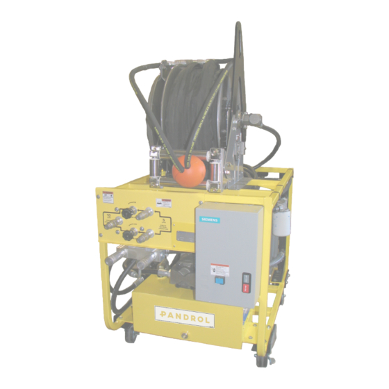
- Page 1 Electric Power Unit MODEL 03700A OPERATION AND MAINTENANCE MANUAL ENG_OMM_ELECTRIC_POWER_UNIT_P01 30th November 2021 Partners in excellence...
-
Page 2: Preface
The manual is intended for people who handle and operate the machine. It is originally written in English and translated into the local language by Pandrol. Pandrol reserves the right to change specifications, equipment, instructions and maintenance guidelines without prior notice. -
Page 3: Table Of Contents
Safety actions 3.3. Personal/Safety equipment 3.4. Safety precautions 3.5. Qualified personnel Summary Operation 5.1. Valve positioning 5.2. Changing tools 5.3. Cold weather operation Trouble shooting guide Calibration procedures for 03700A manifold 7.1. Flow calibration Relief pressure calibration Flow control setting 10. Final calibration and double check 11. Review of hydraulic principles 11.1. Hydraulic formulas 11.2. Back pressure Maintenance 12.1. General 12.2. - Page 4 15.7. Hydraulic and starter relay parts list 15.8. Tool manifold parts diagram 15.9. Tool manifold parts list 15.10. Electric diagram Disclaimer 17. Contact 18. Recycling and Environment OPERATION AND MAINTENANCE MANUAL I ENG_OMM_ELECTRIC_POWER_UNIT_P01 I 30th November 2021 @Pandrol 2021 4 av 34...
-
Page 5: Safety Information
• All safety precautions are given for your safety. Read to understand and follow all safety, maintenance and operation instructions before you use or maintain the tool. • Review the manual daily before using the tool. • Follow all safety guidelines given you by your supervisor. Do not use the tool if you have any questions about the operation, safety or maintenance of this tool . Failure to follow these instructions can result in personal injury or equipment damage. • Pandrol has no control over the tool use or operation once it leaves the plant. Pandrol has no control over operator or maintainer selection. The customer must assume responsibility for the tool suitability for a particular function. • During use of the tool, good judgement must be used to work safely and efficiently without endangering themselves or bystanders. • Understanding of the operation and maintenance manual is essential for anyone using or maintaining the tool. -
Page 6: Personal/Safety Equipment
3.4. Safety precautions • Always wear protective equipment such as gloves, safety glasses, ear protection and safety shoes. • Do not wear clothing which may become entangled in the tool. • Always keep work area free of tools or any other objects which may impair sound footing. • Caution oil injection hazard exists with this tool. Oil injection is a condition where the hydraulic oil is forced under the skin through pressure in the line. Always wear gloves, do not carry the tool by hydraulic hoses, and repair leaks immediately. • Do not operate the power unit until you have been properly trained or under the supervision of a qualified instructor. • Never store engine oil or hydraulic oil near oxygen tanks or lines. • Never add engine oil or hydraulic oil when a spill might come in contact with your oxygen lines, torch or fittings. • Clean up spills immediately. • Never perform grinding or sawing operations that direct sparks into the close proximity of the power unit or flammable materials. • Always turn power unit "OFF" and disconnect hoses before performing any maintenance. OPERATION AND MAINTENANCE MANUAL I ENG_OMM_ELECTRIC_POWER_UNIT_P01 I 30th November 2021 @Pandrol 2021 6 av 34... -
Page 7: Qualified Personnel
• Do not touch electrical connections before you first ensure the power has been disconnected. Only qualified personnel should attempt the installation and maintenance of this equipment. OPERATION AND MAINTENANCE MANUAL I ENG_OMM_ELECTRIC_POWER_UNIT_P01 I 30th November 2021 7 av 34 @Pandrol 2021... -
Page 8: Summary
20 Hp electric 5 GPM (19 LPM) 200 PSI (140 BAR) A - 40” (101.6 cm) 486 lbs (220 kg) 240/360/480 Vac B - 26” (66 cm) 3 Phase 10 GPM (38 LPM) C - 30” (76.2 cm) * See note about Fluid: hydraulic hertz requirements 5 us gal (18.9) liters * Hertz requirements vary by country. Specify requirements when ordering. Accessories: 02326E - Hose reel equipped with 50’ transmission hose. 02323K - Hose reel equipped with 25’ transmission hose. OPERATION AND MAINTENANCE MANUAL I ENG_OMM_ELECTRIC_POWER_UNIT_P01 I 30th November 2021 @Pandrol 2021 8 av 34... -
Page 9: Operation
To change tools, turn the control valves to the off position. • To shut down the power unit turn the control valves to the "OFF" position and depress the red stop button on the breaker box. 5.1. Valve positioning The 03700a power unit is designed to operate either (1) tool at 10 GPM (38 LPM) or (2) tools simultaneously at 5 GPM (19 LPM). Refer to operating instructions for each tool to determine flow requirements. NOTE! • When operating a 10 GPM tool you cannot have any other tool connected to the 5 GPM ports, even if the tool is not being used. OPERATION AND MAINTENANCE MANUAL I ENG_OMM_ELECTRIC_POWER_UNIT_P01 I 30th November 2021... -
Page 10: Changing Tools
5.2. Changing tools • Turn the control knobs to the "OFF" position before disconnecting hoses. • Once the tool has been changed, turn the valves to the "ON" position depending on flow requirements of the tool being used. 5.3. Cold weather operation Hydraulic system performance is affected when the temperature drops below 50°F. Therefore, measures should be taken to pre-warm tools and fluids before operating. NOTE! • Refer to operating procedures of this manual before starting OPERATION AND MAINTENANCE MANUAL I ENG_OMM_ELECTRIC_POWER_UNIT_P01 I 30th November 2021 @Pandrol 2021 10 av 34... -
Page 11: Trouble Shooting Guide
6. Trouble shooting guide • Before any troubleshooting, check hydraulic fluid level and add hydraulic. Oil As required. Also check electrical power supply. • Repair any leaks or obvious damage to power unit. • Maintenance to be performed by qualified maintenance personnel only. Read Operation manual to understand operational characteristics before making Any adjustments. OPERATION AND MAINTENANCE MANUAL I ENG_OMM_ELECTRIC_POWER_UNIT_P01 I 30th November 2021 11 av 34 @Pandrol 2021... - Page 12 Power unit should be moved so unrestricted air movement is available In front, rear and sides of unit. Remember, the cooler draws air from Around the power unit. If the cooler can only draw hot exhaust, captured Air next to bulkhead, or superheated air in truck body hot hydraulic Oil will be the result. • Check tool flow rate. Operate 5 GPM tools only on 5 GPM. Excess Flow at 10 GPM can cause overspeeding of the tool or heat buildup Depending on the tool design. • Make certain that only the control knobs needed for the tool being used are turned on. Having both knobs turned on and only using one 5 GPM tool will allow fluid to be forced over the relief causing over heating. • Check system for excessive back pressure. Back pressure should not exceed 250 PSI - see back pressure section page 34. OPERATION AND MAINTENANCE MANUAL I ENG_OMM_ELECTRIC_POWER_UNIT_P01 I 30th November 2021 @Pandrol 2021 12 av 34...
-
Page 13: Calibration Procedures For 03700A Manifold
7. Calibration procedures for 03700A manifold A flow and pressure test gauge is required for calibrating hydraulic power sources. Pandrol part number 03600 flow and pressure test gauge. Note: procedures should only be performed after the engine has been warmed and the hydraulic oil has reached approximately 70-90 degrees (21-32 celsius). 7.1. Flow calibration Connect the 03600 female coupling onto the 10 GPM (male) port, and the male coupling into the return (female) port. Open top and bottom control valves and read the flow meter, make certain the needle valve is open not restricting flow. You should have a reading of 10 GPM. (As shown) Fig 4. OPERATION AND MAINTENANCE MANUAL I ENG_OMM_ELECTRIC_POWER_UNIT_P01 I 30th November 2021 13 av 34 @Pandrol 2021... -
Page 14: Relief Pressure Calibration
8. Relief pressure calibration With flow and pressure test gauge connected to the 10 GPM port, close the needle valve, and turn on top control valve noting the pressure shown on the gauge. Proper relief setting will be 2000-2100 PSI. (Turn valve off after checking pressure) If you need to adjust the 00139 pressure relief valve. Loosen the jam nut on the 00139 relief valve with a 3/4” deep socket. (Or similar tool) turn the adjustment screw clockwise to increase relief setting. (A 1/4” hex key will be needed for adjustment) turn top valve on noting the pressure on the gauge. After relief pressure has been reached, tighten the jam nut on the 00139 relief valve being careful not to turn pressure adjustment screw. Turn the valve off after setting pressure. Fig 6. Fig 5. OPERATION AND MAINTENANCE MANUAL I ENG_OMM_ELECTRIC_POWER_UNIT_P01 I 30th November 2021 @Pandrol 2021 14 av 34... -
Page 15: Flow Control Setting
9. Flow control setting You will need the pressure test gauge connected to the 10 GPM port. Using the 3/4” deep socket (or similar tool) and 1/4” hex key, loosen jam nut on the 00141-01 flow control valve and turn adjustment screw clockwise until it seats. (Do not over tighten) Fig 7. Turn bottom control valve on and off until pressure remains on gauge. (Approximately 1500 PSI) this pressure will remain on the gauge until the 00141-01 flow control valve is adjusted. Slowly turn the adjustment screw counterclockwise until pressure suddenly drops to zero. Tighten the jam nut on the 00141-01 flow control valve being careful not to turn the adjustment screw. Check the initial setting by turning the control valve on (full relief 2000-2100 PSI) and off making sure that the pressure drops to zero. OPERATION AND MAINTENANCE MANUAL I ENG_OMM_ELECTRIC_POWER_UNIT_P01 I 30th November 2021 15 av 34 @Pandrol 2021... -
Page 16: Final Calibration And Double Check
10. Final calibration and double check Connect the test gauge to the top 5 GPM port. With needle valve opened, turn on top control valve. Flow meter should read 5 GPM. Turn needle valve in to pressurize system to 1500 PSI and note the flow meter. You should not see more than 1/ 2 a GPM drop. (4 1/2 GPM flow) the bottom 5 GPM port will be tested in the same manner. (Using the bottom control valve) If the bottom 5 GPM port reads any less than 4 1/2 GPM, then you will have to recalibrate the 00141-01 flow control valve. Loosen jam nut and very slightly turn adjustment nut clockwise and tighten jam nut. Remove the gauge and turn valves on and off, connect it to the 10 GPM port. If it goes on easily, adjustment is complete. Move the gauge to the 10 GPM port and turn both control valves on. Flow meter should read 10 GPM turn needle valve in to pressurize system to 1500 PSI and note the flow meter. You should not see more than 1/2 a GPM drop. (9 1/2 GPM flow) Fig 9. Fig 8. This completes the calibration procedure. If any problems are encountered, please contact Pandrol for technical service. OPERATION AND MAINTENANCE MANUAL I ENG_OMM_ELECTRIC_POWER_UNIT_P01 I 30th November 2021 @Pandrol 2021 16 av 34... -
Page 17: Review Of Hydraulic Principles
8.58 10.30 3.43 6.86 10.30 13.70 17.20 20.60 5.15 10.30 15.40 20.60 25.70 30.90 11.2. Back pressure Back pressure measured at the tool return port must not exceed the manufacturers back pressure rating. Most manufacturers list the maximum back pressure for their hydraulic tools at 250 PSI. Back pressure measured on the return side of the tool is the force required to get the oil back to the tank. In almost all cases the lower the back pressure the better the tool performance. First, the back pressure is subtracted from the maximum tool pressure to arrive at a maximum tool operating pressure. For example, tools with 2000 PSI operating pressure are installed on a system with 250 PSI back pressure. This leaves 1750 PSI as a maximum tool pressure. Imagine a system with 500 PSI back pressure. 2000 Minus 500 PSI back pressure leaves only 1500 PSI for the tool. Second, tools are designed for pressure to build on the pressure side of the tool. If too much pressure builds on the return side, not only is performance effected, but seals may blow. This is why it is very important to direct the flow into the tool correctly. Reversing the hoses to test may result in blown seals, damage to the tool, and personal injury. OPERATION AND MAINTENANCE MANUAL I ENG_OMM_ELECTRIC_POWER_UNIT_P01 I 30th November 2021 17 av 34 @Pandrol 2021... -
Page 18: Maintenance
12.1. General Maintenance and overhaul is to be carried out by qualified personnel only Warranty is based on parts and spares delivered by Pandrol. Check tools DAILY for proper operation, leaks, or damage. Inspect hoses DAILY. Replace cut, burned, or otherwise damaged hoses. -
Page 19: Warning Labels And Information Symbols
12.2. Warning labels and information symbols Below are examples of warning labels and information symbols on the machine. If any of these labels become damaged or lost, they are to be replaced with new original warning labels that are available from Pandrol. OPERATION AND MAINTENANCE MANUAL I ENG_OMM_ELECTRIC_POWER_UNIT_P01 I 30th November 2021 19 av 34 @Pandrol 2021... -
Page 20: Limited Warranty
As a condition precedent to Pandrol’s obligation hereunder, the defective product must not have been altered or modified without the express written approval of Pandrol. The product must not have been subjected to deliberate damage, shipping damage, neglect, tampering by unauthorized personnel or damage by improper use, storage or maintenance. Serial numbers must not have been altered, defaced or removed. Such action voids limited warranty. 13.1. Exclusions to limited warranty This limited warranty is exclusive and is in lieu of any other warranty, written or oral, expressed or implied, including, without limitation, any implied warranty or merchantability or fitness for a particular purpose. Limited warranty does not cover normal wear and tear items such as filters, hoses, couplers, bits, sockets, augers, and batteries 13.2. Limitation of liability Except as provided above, Pandrol shall in no event be liable or responsible for any injury, loss or damage, direct, incidental or consequential, arising out of the use or misuse or inability to use the product, however caused and on any theory of liability including, without limitations, breach of contract, tort, (including negligence or street liability) and not withstanding any failure of any remedy herein of its essential purpose, even if Pandrol was aware of this possibility of such damage. Pandrol’s limited warranty as set forth above shall not be enlarged, diminished or affected by, and no obligation or liability shall arise or go out of the rendering of technical advice or service by Pandrol or its agents. The foregoing may not be changed except by written agreement signed by an authorized officer of Pandrol, the remedies set forth herein are exclusive. OPERATION AND MAINTENANCE MANUAL I ENG_OMM_ELECTRIC_POWER_UNIT_P01 I 30th November 2021 @Pandrol 2021 20 av 34... -
Page 21: Customer Information
14. Customer information Name Company Serial # of your Pandrol tool Upon receiving your Pandrol tool, make sure to list serial number above so that a good record is kept for order information. Pandrol hydraulic tool list All Pandrol Hydraulic Tools operate at 5 GPM (19 LPM) or 10 GPM (38 LPM) @ 2000 PSI (140 BAR) Power units: 00100K – Gasoline powered (1) 10 GPM or (2) 5 GPM circuits... - Page 22 01200 – Spring anchor applicator 01100A – Spike puller (Single, 2 stage & trigger versions available) 00800A – 16” Rail saw 05000 – Hand pump weld shear 02500 – 10 GPM 1” Impact wrench 08300 – Spike driver 01600A – 5 GPM 1” Impact wrench 01100RM – Light-weight spike puller Other products: Hydraulic manifolds Hydraulic test gauges Hose reels Hydraulic hoses Accessories Drill bits Shear Blades Saw Blades Grinding Stones Sockets OPERATION AND MAINTENANCE MANUAL I ENG_OMM_ELECTRIC_POWER_UNIT_P01 I 30th November 2021 @Pandrol 2021 22 av 34...
-
Page 23: Assembly
15. Assembly 15.1. Flow diagram OPERATION AND MAINTENANCE MANUAL I ENG_OMM_ELECTRIC_POWER_UNIT_P01 I 30th November 2021 23 av 34 @Pandrol 2021... -
Page 24: Frame Parts Diagram
15.2. Frame parts diagram OPERATION AND MAINTENANCE MANUAL I ENG_OMM_ELECTRIC_POWER_UNIT_P01 I 30th November 2021 @Pandrol 2021 24 av 34... -
Page 25: Frame Parts List
15.3. Frame parts list OPERATION AND MAINTENANCE MANUAL I ENG_OMM_ELECTRIC_POWER_UNIT_P01 I 30th November 2021 25 av 34 @Pandrol 2021... -
Page 26: Engine And Pump Parts Diagram
15.4. Engine and pump parts diagram OPERATION AND MAINTENANCE MANUAL I ENG_OMM_ELECTRIC_POWER_UNIT_P01 I 30th November 2021 @Pandrol 2021 26 av 34... -
Page 27: Engine And Pump Parts List
15.5. Engine and pump parts list OPERATION AND MAINTENANCE MANUAL I ENG_OMM_ELECTRIC_POWER_UNIT_P01 I 30th November 2021 27 av 34 @Pandrol 2021... -
Page 28: Hydraulic And Starter Relay Parts Diagram
15.6. Hydraulic and starter relay parts diagram OPERATION AND MAINTENANCE MANUAL I ENG_OMM_ELECTRIC_POWER_UNIT_P01 I 30th November 2021 @Pandrol 2021 28 av 34... -
Page 29: Hydraulic And Starter Relay Parts List
15.7. Hydraulic and starter relay parts list OPERATION AND MAINTENANCE MANUAL I ENG_OMM_ELECTRIC_POWER_UNIT_P01 I 30th November 2021 29 av 34 @Pandrol 2021... -
Page 30: Tool Manifold Parts Diagram
15.8. Tool manifold parts diagram OPERATION AND MAINTENANCE MANUAL I ENG_OMM_ELECTRIC_POWER_UNIT_P01 I 30th November 2021 @Pandrol 2021 30 av 34... -
Page 31: Tool Manifold Parts List
15.9. Tool manifold parts list OPERATION AND MAINTENANCE MANUAL I ENG_OMM_ELECTRIC_POWER_UNIT_P01 I 30th November 2021 31 av 34 @Pandrol 2021... -
Page 32: Electric Diagram
15.10. Electric diagram OPERATION AND MAINTENANCE MANUAL I ENG_OMM_ELECTRIC_POWER_UNIT_P01 I 30th November 2021 @Pandrol 2021 32 av 34... -
Page 33: Disclaimer
16. Disclaimer Pandrol exempts itself from liability in the event of usage that deviates from that recommended in this manual. 17. Contact Address Phone Internet and E-mail www.Pandrol.com 18. Recycling and Environment Sustainable environment is a great part of Pandrol. All components of the product can either be: • Recycled • Taken care of • Be re-used We recommend you to follow your local region regulations of environmental and recycling policies. OPERATION AND MAINTENANCE MANUAL I ENG_OMM_ELECTRIC_POWER_UNIT_P01 I 30th November 2021 33 av 34 @Pandrol 2021... - Page 34 Find out more at pandrol.com Pandrol ©Pandrol Partners in excellence...
Need help?
Do you have a question about the 03700A and is the answer not in the manual?
Questions and answers