RollSeal RS-600M Installation And Operation Manual
Intrinsically safe barrier door
Hide thumbs
Also See for RS-600M:
- Installation and operation manual (57 pages) ,
- Training manual (11 pages) ,
- Installation and operation manual (72 pages)

Related Manuals for RollSeal RS-600M

Summary of Contents for RollSeal RS-600M
- Page 1 RS-600M Intrinsically Safe Barrier Door Installation and Operation Manual 4801-9003U...
-
Page 2: Table Of Contents
Section 5.2: P12 Input Status Indicators............................Section 5.3: Error Codes and Recommended Actions........................Section 5.4: Drive Board Diagnostic LEDs............................Section 5.4.1: Door Idle..................................Section 5.4.2: Door Moving.................................. Section 5.5: Testing Brake Relay..............................RS-600M Intrinsically Safe Barrier Door Installation and Operation Manual... - Page 3 Table of Contents Section 6: Accessories............................Section 6.1: Passive Infrared Motion Sensor........................... Section 6.2: Wave Close Proximity Sensor............................Section 6.3: Large Door Motion Sensor............................Section 6.4: One-button Control Station............................Section 6.5: Two-button Control Station with Key Lock......................... Section 6.6: Pull-cord Switch................................Section 6.7: Remote Receiver and Transmitter..........................
-
Page 4: Section 1: Introduction
To ensure mechanical safety, additional safety devices such as electromechanical interlocks may be required. Only qualified personnel familiar with the construction and operation of this equipment and the hazards involved are to install, adjust, and/or service this equipment. RS-600M Intrinsically Safe Barrier Door Installation and Operation Manual... -
Page 5: Section 1.1.3: Product Labels
No entity has the authority to bind RollSeal to any representation or warranty other than this Limited Warranty. RollSeal shall not be liable for any damages or losses resulting from any application of the Product or caused by any defect, failure, or malfunction of the Product. -
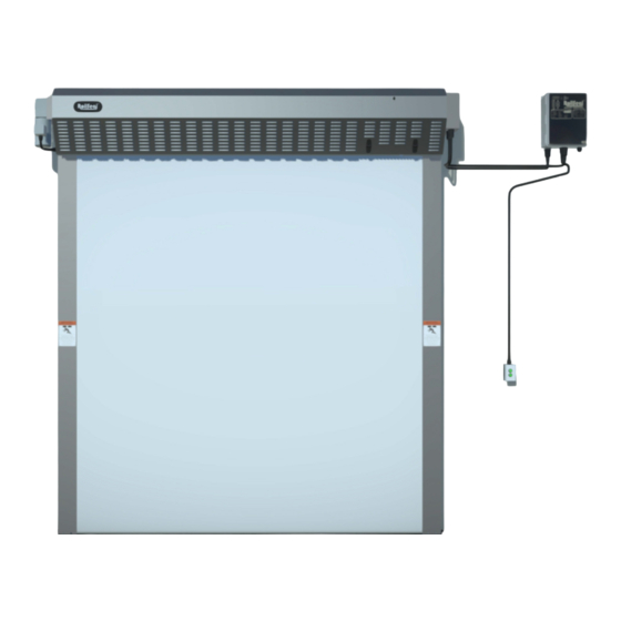
Page 6: Section 1.3: Overview
Section 1.3: Overview The SC-650M ISB Smart Controller is manufactured specifically for the RollSeal automated door. It uses internal safety devices, in conjunction with components of the door assembly, to open and close the door automatically. The Smart Controller can also manage the opening and closing speeds of the door, count the number of cycles the door has performed, and provide status information for remotely monitoring the door's position. - Page 7 Classification Area Classification Substance Substances Covered by Hazardous Location Characteristics Class NEC 500 NEC 505 UL Listing Explosion hazard is present continuously Zone 0 Division 1 or occasionally under normal operating Zone 1 conditions. Class I Gases/Vapors (NEC 501) Ignitable concentrations of flammable Division 2 Zone 2 Yes (Section 1.4.1)
-
Page 8: Section 1.4: Dimensions
Components within the dashed box are located inside a Class I, Division 2 hazardous area. Mechanical switches in the hazardous area are considered a simple apparatus and are investigated as part of the overhead door system. RS-600M Intrinsically Safe Barrier Door Installation and Operation Manual... -
Page 9: Section 1.4.2: Sc-650M Isb Smart Controller
Section 1.4.2: SC-650M ISB Smart Controller 4801-9003U... -
Page 10: Section 2: Installation
RollSeal distributor immediately. This document is subject to change without notice. The latest version is maintained at rollseal.net/rollseal-technicals/. If you require assistance during any part of the procedure, contact RollSeal Technical Support at 1-800-668-2815. Section 2.1: Scope of Work The installer is responsible for the following: •... -
Page 11: Section 2.2: Adjust Framing And/Or Clear Opening
Section 2.2: Adjust Framing and/or Clear Opening Using the diagram in Section 1.4.1, determine the required width and height of the clear opening. If necessary, adjust the dimensions of the mounting posts and/or framing members to suit the dimensions of the door. The framing material must provide adequate support for screws. -
Page 12: Section 2.3: Splice Tracks (If Taller Than 13')
Align the bolt holes in the splice brackets with the bolt holes in the tracks. Fasten the tracks and the splice brackets together using the included blind-head bolts and 1/4"-20 finish nuts. Front Back Before After RS-600M Intrinsically Safe Barrier Door Installation and Operation Manual... -
Page 13: Section 2.4: Connect Tracks To Head Unit
Section 2.4: Connect Tracks to Head Unit Each end of the head unit has a U-shaped plate that fits the corresponding track. The plate has four bolt holes (two on the outside and two on the inside) that match the bolt holes in the tracks. Arrange the head unit and both tracks on the floor, face-down in front of the clear opening. -
Page 14: Section 2.5: Mount Door To Clear Opening
Drill a 1/4" hole in each of the two floor mounting holes at the bottom of the left track, then install the provided concrete anchors. Repeat this step on the right track. RS-600M Intrinsically Safe Barrier Door Installation and Operation Manual... -
Page 15: Section 2.6: Mount And Wire Smart Controller
Section 2.6: Mount and Wire Smart Controller Using four screws, mount the Smart Controller outside the 3' classified area. The provided cable is long enough for the Smart Controller to be mounted up to 15' from the head unit. Ensure the Smart Controller is not connected to power. Plug the circular plastic connectors (CPCs) from the AC and DC harnesses (located at the bottom of the enclosure on the right side of the head unit) into the receptacles on the bottom of the controller. -
Page 16: Section 2.7: Mount And Wire Switches
(Section 2.7.2); or through two perpendicular walls with a bridge plenum (Section 2.7.3). RollSeal recommends using a prewired activation switch kit. Open and close signals are wired through intrinsically safe barriers. Other activation devices should not be used unless they are classified for use in the operating environment. - Page 17 Outside Switch Inside Switch 4801-9003U...
-
Page 18: Section 2.7.2: Two Parallel Walls Separated By Void
Route the inside switch harness through the hole, then connect the CPC to the bottom of the outside switch. Install escutcheon plates over the holes you drilled in Step 4 and Step 6. Install P-clamps on the conduit as required. Mount one near the CPC to prevent tampering. RS-600M Intrinsically Safe Barrier Door Installation and Operation Manual... - Page 19 Outside Switch Inside Switch 4801-9003U...
-
Page 20: Section 2.7.3: Two Perpendicular Walls With Bridge Plenum
Install escutcheon plates over the holes you drilled in Step 3 and Step 5. 10. Install P-clamps on the conduit as required. Mount one near the CPC to prevent tampering. Inside Switch Outside Switch RS-600M Intrinsically Safe Barrier Door Installation and Operation Manual... -
Page 21: Section 2.8: Connect Infrared Safety Beam System
Section 2.8: Connect Infrared Safety Beam System An infrared emitter and receiver are connected to the outside of the tracks. If the invisible beam is interrupted (e.g., by a person or a forklift) while closing, the door will stop and reverse to the fully open position (see Section 3.3). Access the enclosure: - If the motor is mounted on the left side of the head unit, locate the enclosure on the right side of the head unit. -
Page 22: Section 2.8.1: Connect Extension Harness (If Door Is Taller And/Or Wider Than 15')
Coil any slack on top of the booth or the head unit, then zip-tie it. Tighten the enclosure strain reliefs. Reinstall the enclosure cover or harness plate using the original fasteners. RS-600M Intrinsically Safe Barrier Door Installation and Operation Manual... -
Page 23: Section 2.9: Power
Section 2.9: Power All RollSeal doors and controllers are ordered according to specific power requirements, which are listed in Section 1.3 and on the door's serial number label. Contact RollSeal for details. All user-supplied conduit and fittings must be rated for IP54. -
Page 24: Section 2.10: Install Motor Crank Handle
21. If the door has not yet been connected to its permanent power supply, do so before the door enters regular operation. To prevent unauthorized access, the installer must either add a lock to the controller enclosure or reinstall the included nut and bolt. RS-600M Intrinsically Safe Barrier Door Installation and Operation Manual... -
Page 25: Section 3: Operation
Section 3: Operation Section 3.1: Switches and Smart Controller The door can be opened and closed using the switches (during normal operation) or the Smart Controller (if necessary). Press and release the Open or Close button to open or close the door, respectively. If an error prevents the door from functioning, press and hold the button to engage a constant-pressure override. -
Page 26: Section 3.2: Home Sensor And Leading Edge Switch
If the door is obstructed while it closes, the leading edge switch will stop the door from moving, then immediately reverse it to its open limit. If the leading edge switch is tripped, the Door Obstruction LED on the Display Indicator will be illuminated (see Section 5.2). Leading Edge Switch Home Sensor RS-600M Intrinsically Safe Barrier Door Installation and Operation Manual... -
Page 27: Section 3.3: Infrared Safety Beam
Section 3.3: Infrared Safety Beam The infrared emitter installed near the bottom of the door produces a constant, invisible beam that is ordinarily intercepted by the receiver. If this beam is interrupted (e.g., by a person or a forklift) while the door is closing, the door will stop and reverse to the fully open position. -
Page 28: Section 3.6: Smart Controller User Interface
See Section 3.7.1 for details on resetting this reading and on setting service reminders. Total Cycles and Service Cycles are represented by the same LED. After selecting Total Cycles, press the Mode button once to display Service Cycles. RS-600M Intrinsically Safe Barrier Door Installation and Operation Manual... -
Page 29: Section 3.6.2: Display Indicator Readings
Section 3.6.2: Display Indicator Readings In addition to the togglable readings defined in Section 3.6.1, the Display Indicator sometimes shows other values that represent the Smart Controller's status. Software Version and Model Number When the Smart Controller is powered on, the Display Indicator flashes the current software version and the model number for approximately two seconds. - Page 30 The Door Obstruction LED (a red dot at the bottom-right corner of the Display Indicator) will be illuminated until the obstruction is cleared. RS-600M Intrinsically Safe Barrier Door Installation and Operation Manual...
-
Page 31: Section 3.7: Configuration
Section 3.7: Configuration Section 3.7.1: Program Mode Settings defined when the Smart Controller is installed or adjusted are known as program parameters. Each program parameter is assigned a code by which it is identified on the Display Indicator: Program Parameters P1: Close Time Delay P11: Service Reminder P24: CMS Output Function... - Page 32 This configures the Warning Output to signal when the door is fully open for monitoring. - P4 = 4 (Door Closed Signal) This configures the Warning Output to signal when the door is fully closed for monitoring. RS-600M Intrinsically Safe Barrier Door Installation and Operation Manual...
- Page 33 P7 - Refresh Door Limits (Default 25) This parameter allows the user to set the number of open and close cycles that must be performed before the door refreshes the Open and Closed Limits (see Section 3.7.4), which may be necessary if the limits desynchronize from the encoder. This parameter can be set between one cycle (i.e., the limits are refreshed every time the door opens) and 25 cycles.
- Page 34 This parameter determines the period of time (measured in minutes) the J13-AUX #2 relay remains on should the application require it to be switched on and off; P26 dictates the off time. Contact RollSeal Technical Support if this is necessary.
-
Page 35: Section 3.7.2: Open And Close Speeds
PS1 - Change Program Limits This parameter can be set to either "Yes" or "No". To change the Open Limit (PS2) or the Closed Limit (PS3), set this parameter to "Yes", then press the Mode button. To exit Program Mode while this parameter is selected, set PS1 to "No", then press the Mode button;... -
Page 36: Section 3.7.3: Deceleration Range
Jog Mode was disengaged; the Display Indicator will thus show a series of three horizontal bars. Upon the next command the door will slowly proceed to the fully open position to reset the Smart Controller's memory; the door will always follow this procedure upon exiting Jog Mode. RS-600M Intrinsically Safe Barrier Door Installation and Operation Manual... -
Page 37: Section 3.9: Door Activation Inputs
Section 3.9: Door Activation Inputs Section 3.9.1: Directional Switch The directional switch input (controlled by program parameter P20; see Section 3.7.1) is primarily used with a three-position directional switch that opens, stops, or closes the door when the corresponding button is pressed. However, the Smart Controller can be programmed to hold the door in the fully open, stopped, or fully closed position when the corresponding button is pressed and held. -
Page 38: Section 3.10: Relay Outputs
To report a door closed signal to two controls, use AUX #1 with P4 set to 4 for the former, and use AUX #2 with P24 set to 1 for the latter. Outputs DCP: DC Power DIR: Directional Switch ENC: Encoder AX2: AUX #2 SFB: Safety Beam AX1: AUX #1 LIM: Limits SEQ: Sequential Switch RS-600M Intrinsically Safe Barrier Door Installation and Operation Manual... -
Page 39: Section 4: Maintenance
Section 4: Maintenance Section 4.1: Cleaning and Adjusting Components Section 4.1.1: Cleaning Panels and (if Present) Window The door panels (and the window, if present) can be cleaned by gently wiping any soiled areas with a cloth and mildly soapy water. Rinse the area with water to remove the solution, then immediately dry the panels using a separate cloth. - Page 40 RS-600M Intrinsically Safe Barrier Door Installation and Operation Manual...
-
Page 41: Section 4.1.3: Adjusting Brake
Section 4.1.3: Adjusting Brake After extended operation, the brake may become worn and require adjustment. Lower the door to the fully closed position. Disconnect power from the motor. Remove the four Phillips-head screws (A), then remove the motor cover (B). Straighten the bent tab on the spider nut (C). -
Page 42: Section 4.2: Replacing Components
10. Turn the Smart Controller on. 11. Enter Jog Mode, then jog the door up and down until the panels are straight. 12. Exit Jog Mode, then attempt to operate the door normally. RS-600M Intrinsically Safe Barrier Door Installation and Operation Manual... - Page 43 Center Panel Front Panel Back Panel 4801-9003U...
- Page 44 RS-600M Intrinsically Safe Barrier Door Installation and Operation Manual...
-
Page 45: Section 4.2.2: Hook-And-Loop Seal
Section 4.2.2: Hook-and-Loop Seal The hook-and-loop seal can be replaced as follows: Turn off power to the Smart Controller. Raise the door to its upper limit. Remove the PEM plate nuts from the side of one of the tracks. Remove the PEM plates and the seal assemblies from the tracks. Place the PEM plate on the floor, then remove the seal from it. -
Page 46: Section 5: Troubleshooting
Turn the crank handle counterclockwise until the door is high enough to allow passage. Flip the lever in the opposite direction to re-engage the brake. The motor can become damaged if the brake lever is not re-engaged. RS-600M Intrinsically Safe Barrier Door Installation and Operation Manual... -
Page 47: Section 5.2: P12 Input Status Indicators
Section 5.2: P12 Input Status Indicators This program parameter is used to service and troubleshoot the door. The inputs are represented by LED segments on the Display Indicator. If an LED segment is on, the corresponding switch is closed. If the segment is off, the switch is open. Important P12 status indicators are as follows: For the door to close, the Primary Safety and Leading Edge segments must be off. -
Page 48: Section 5.3: Error Codes And Recommended Actions
Down Encoder Reverse signal wires. EOF3 Opening; Motor Stall Fault Motor Stall Fault ECF3 Closing; Motor Stall Fault EOF4 Opening; Over Speed Fault Over Speed Fault ECF4 Closing; Over Speed Fault RS-600M Intrinsically Safe Barrier Door Installation and Operation Manual... -
Page 49: Section 5.4: Drive Board Diagnostic Leds
Section 5.4: Drive Board Diagnostic LEDs The drive's condition is indicated by a pair of LEDs (Power ["PWR"] and Status ["ST"]) on the drive board. The LEDs may remain solid, flash slowly (on one second; off one second), or flash quickly (on 0.25 seconds; off 0.25 seconds). Section 5.4.1: Door Idle Power LED Status LED... -
Page 50: Section 5.5: Testing Brake Relay
Listen for a clicking sound coming from the brake, and watch for the panels to drop, to verify the relay is functioning properly. If the conditions in Step 3 are not met, contact RollSeal Technical Support. RS-600M Intrinsically Safe Barrier Door Installation and Operation Manual... -
Page 51: Section 6: Accessories
Section 6: Accessories Section 6.1: Passive Infrared Motion Sensor The Passive Infrared Motion Sensor requires both heat and motion to activate the switch, eliminating the false triggers that commonly affect motion-only sensors. The sensor has a small footprint and can be mounted in multiple locations on and around the door. -
Page 52: Section 7: Replacement Parts
Section 7: Replacement Parts Section 7.1: General RS-600M Intrinsically Safe Barrier Door Installation and Operation Manual... - Page 53 Callout Part Number Description Based on Size Gear Motor 1903-3109 Leading Edge Switch/Harness 1903-3125 Home Switch/Harness 6540-0089 Hall Effect Encoder Based on Size Smart Controller (See Section 8.2 for sub-assemblies.) 6540-0684 Infrared Safety Beam Emitter/Receiver Based on Size Floating Seal Based on Size PEM Plate Based on Size...
-
Page 54: Section 7.2: Smart Controller
Callout Part Number Description 6407-0615 Door Control Board 6407-6086 Drive Board 6407-6088 Brake Module (if Equipped) 3001-7018 Disconnect Switch 6407-1724 PCB 207 3015-3102 Two-Channel Intrinsic Barrier Assembly 1903-6146 Audible Alarm Buzzer/Harness RS-600M Intrinsically Safe Barrier Door Installation and Operation Manual... -
Page 55: Section 8: Diagrams
Section 8: Diagrams Section 8.1: Door Internal Wiring 4801-9003U... -
Page 56: Section 8.2: Smart Controller
Section 8.2: Smart Controller Section 8.2.1: Layout RS-600M Intrinsically Safe Barrier Door Installation and Operation Manual... -
Page 57: Section 8.2.2: Internal Wiring
Section 8.2.2: Internal Wiring 4801-9003U... -
Page 58: Section 8.3: Interlocking Two Doors
Section 8.3: Interlocking Two Doors RS-600M Intrinsically Safe Barrier Door Installation and Operation Manual... -
Page 59: Section 8.4: Connecting Two-Button Switches
Section 8.4: Connecting Two-button Switches NOTICE: RollSeal recommends using a prewired activation switch kit. Open and close signals are wired through intrinsically safe barriers. Other activation devices should be wired through these channels unless classified for use in the operating environment. -
Page 60: Section 8.5: Connecting Other Switches
Open and close signals are wired through intrinsically safe barriers. Other activation devices should be wired through these channels unless they are classified for use in the operating environment. RS-600M Intrinsically Safe Barrier Door Installation and Operation Manual... -
Page 61: Section 8.6: Connecting Remote Receiver
Section 8.6: Connecting Remote Receiver 4801-9003U... -
Page 62: Section 8.7: Connecting Large Door Motion Sensor
Section 8.7: Connecting Large Door Motion Sensor NOTICE: The sensor comes preset to the ideal range and sensitivity for most applications. See the included manufacturer documentation for information on adjusting these parameters. RS-600M Intrinsically Safe Barrier Door Installation and Operation Manual...
Need help?
Do you have a question about the RS-600M and is the answer not in the manual?
Questions and answers