Table of Contents
Advertisement
Quick Links
Advertisement
Table of Contents

Related Manuals for Richmond GTR510

Summary of Contents for Richmond GTR510
- Page 1 GTR510 SLIDING GATE MOTOR Software Version: PS22091 User Manual...
-
Page 2: Table Of Contents
INDEX 1. WARNINGS _________________________________________________________ 1 2. INSTALLATION ______________________________________________________ 2 A. STANDARD INSTALLATION DEMONSTRATION B. DESCRIPTION OF DEVICE ___________________________________________ 2 C. DIMENSION OF DEVICE ______________________________________________ 3 D. INSTALLATION OF MOTOR GEAR AND GEAR RACK _______________________ 3 E. CHECKING FOR INSTALLATION _______________________________________ 4 F. -
Page 3: Warnings
1. GENERAL PRECAUTION: WARNING : This user manual is only for qualified technicians who is specialized in installations and automations. (1) All installations, electrical connections, adjustments and testing must be performed only after reading and understanding of all instructions carefully. (2) Before carrying out any installation or maintenance operation, disconnect the electrical power supply by turning off the magneto thermic switch connected upstream and apply the hazard area notice required by applicable regulations... -
Page 4: Installation
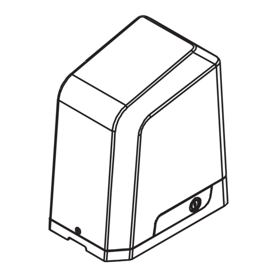
2. INSTALLATION: STANDARD INSTALLATION DEMONSTRATION 1. 24Vdc sliding motor 2. Transmitter 3. Safety photo sensor 4. Flashing light DESCRIPTION OF DEVICE a. Operation gear e. Release device b. Limit switch device f. Control panel under the cover c. 24Vdc motor g. -
Page 5: Dimension Of Device
DIMENSION OF DEVICE INSTALLATION OF MOTOR GEAR AND GEAR RACK Place the first rack on the driving pinion and trace the drilling locations completely. The rack must be perfectly horizontal. Mark a trait on the top of rack. Proceed in this way over the entire length of the gate. (Figure 2) Note: Help yourself to use one piece of rack to stabilize 2 pieces of racks. -
Page 6: Checking For Installation
CHECKING FOR INSTALLATION EMERGENCY RELEASE In the case of power failure for emergency release of the motor, please follow the procedure as below: Step1 & Step2. Insert the key and turn clockwise to unlock the device. Step3. Pull the release bar. Step1 Step2 Step3... -
Page 7: Setup And Function Setting
3. SETUP AND FUNCTION SETTING WIRE CONNECTION Flashing Push Light NO NC COM Button Selector... -
Page 8: Transmitter Memorization And Erasing Process
TRANSMITTER MEMORIZING AND ERASING PROCESS (1) Transmitter Memorizing: Press “RF Learn” button for 3 seconds, and the LED display shows “CS”; then press the transmitter left button (A); the LED display will blink three times and stay on, and after 7 seconds without any new remote learn then the LED will be 1 2 3 off The transmitter learning is completed. -
Page 9: How To Set The Parameter
LED Display Programmable Functions LED Display Programmable Functions “-L”: The system learning is not done. “LE”: Enter learning mode and then wait for learning instructions. “OP”: The system is in normal operation To “LP”: The system learning is in progress. program, press SET button for 3 seconds, The Auto-learning process of gate moving: “Gate open to the end- stop close to the... - Page 10 Definition Function Value Description 1. The function can adjust the running force of motor to Opening Overcurrent Setting 81 be compatible with the gate weight. 2. The default setting is "87". WARNING: The maximum overcurrent for 500kg motor is 10A, it may have the potential risk if the adjustment over 10A current.
- Page 11 Definition Function Value Description 1.The default setting is "P0". Photocell 2 Activation Function OFF (Default) Function ON PCB Stop Terminal The default setting is "U0". Function OFF (Default) Activation Function ON Pb Terminal Function 1. The default setting is "A.1" Open-Stop-Close-Stop (Default) 2.
-
Page 12: Recognition Of Led
LED1 will be on when the first pair of the photocells are activated. LED2 Photocells Indicator LED2 will be on when the second pair of the photocells are activated. 4. Technical Characteristics: TECHNICAL DATA SHEET OF SERIES Motor GTR510 Thrust 8000N Motor RPM 3600RPM Wattage... - Page 13 NZ: 0800 61 71 81 International: +613 9551 2233 Richmond Wheel & Castor Co. declines all responsibility for any consequences resulting from improper use of the product, or use which is different from the expected and specified in the present documentation.
Need help?
Do you have a question about the GTR510 and is the answer not in the manual?
Questions and answers