
Related Manuals for Nordcap CD 140


Summary of Contents for Nordcap CD 140
- Page 1 Bedienungsanweisung Kühl- / Tiefkühl-Kombinationsschrank CD 140 [Art. 435800140] 2022-01...
-
Page 2: Table Of Contents
Table of Content Introduction 3 Important Notes .................................. 3 Product Temperature Classes ............................ 4 Climate Classes .................................. 4 Air Velocity .................................... 4 Safety Instructions ................................ 4 Electrical Safety Tests (EST) ............................... 5 Risk Analysis .................................... 6 Working with HC R290 (Propane) .............................. 6 Risk Assessment ‐ Zoning................................ 8 Cabinet Use 9 Important .................................... 9 Shelf Loading for Proper Cold Air Circulation .......................... ... - Page 3 Side Elevations .................................. 2 3 Case Layout ..................................... 2 4 Shelving Profiles .................................. 2 5 Cabinet Data Plate Descriptions .............................. 2 6 Refrigeration ................................... 2 7 Noise Breakout .................................. 2 7 Service and Maintenance .................................. 2 8 Access to fans .................................. 2 8 Access to drainage outlets............................... 2 8 Access to cabinet electrics and controls .......................... 2 8 Condensing Group Carrier ............................... 2 8 Cabinet Operation ................................... ...
-
Page 4: Introduction
1 Introduction The CALLISTO DUAL cabinets are retail refrigerated display cabinet with integrated condensing units for displaying chilled food. This cabinet is designed and built for TEFCOLD for storing chilled and deep frozen products. It cannot be used to cool hot, non‐chilled products, freeze chilled and/or non‐frozen products. This manual has to be read before handling or installing or using the product. This manual contains ... -
Page 5: Product Temperature Classes
The buyer is responsible for training personnel using the appliance on the risks, safety devices and general health and safety rules required by the laws of the country where the appliance is installed. Users/operators should be aware of the position of all the controls and how they work, as well as of the features of the appliance. They should also read this manual in it’s entirely. Maintenance work should be conducted by qualified personnel after the appliance has been prepared adequately. 1.2 Product Temperature Classes MEAT M1 (warmer than or equal to ‐1˚C, colder than or equal to +5˚C) FROZEN FOOD L1 (colder than or equal to ‐18˚C, colder than or equal to ‐15˚C) 1.3 Climate Classes The CALLISTO DUAL cabinets are designed to maintain nominal product temperatures above referring to EN ISO 23953‐2:2015 in an ambient environment of 25˚C dry bulb temperature and ... -
Page 6: Electrical Safety Tests (Est)
The water which comes from the cabinet’s evaporator during defrost period, has to be drained from an outlet. Therefore, drainage pipes must be installed from this outlet to a suitable external drain point. Otherwise, defrost water could collect in the back of the cabinet and damage internal components. The customer should check periodically whether the outlets are blocked or not. Sections with the below sign, should only be accessed by authorized personnel. Do not forget that electricity can be fatal. Do not store explosive substances such as aerosol cans with a flammable propellant in this cabinet. ... -
Page 7: Risk Analysis
TEFCOLD highly recommend that the cabinet is only connected to a power supply protected by an earth leakage relay. In the event of an electrical fault the equipment must be electrically isolated immediately and power must not be restored until authorised by competent electrical personnel. 1.7 Risk Analysis The below Risk Analysis tables show potential problems and who may be affected. The aim of these tables is to prevent possible problems or injuries before they occur. Use of electrical Isolator WHO WHAT REDUCTION Store personnel Electrical Shock Live parts mech. covered Store personnel Falling whilst using isolator Correct use approved steps Electrical Maintenance WHO WHAT REDUCTION Maintenance Personnel Electrical Shock Isolate before working Maintenance Personnel Falling whilst using isolator Correct use approved steps Cleaning cabinet WHO WHAT REDUCTION Cleaning personnel ... - Page 8 Work Procedure Work shall be undertaken under a controlled procedure so as to minimise the risk of a flammable gas or vapour being present while the work is being performed. General Work Area All maintenance staff and others working in the local area should be instructed as to the nature of work being carried out. Work in confined spaces must be avoided. The area around the workspace is to be sectioned off. Ensure that the conditions within the area have been made safe by control of flammable material. ...
-
Page 9: Risk Assessment - Zoning
1.9 Risk Assessment ‐ Zoning ... -
Page 10: Cabinet Use
2 Cabinet Use 2.1 Important Do not put warm or un‐chilled products into the cabinet. It is designed to hold pre‐chilled products, not to cool them (Chilled Section). Do not put chilled and/or non‐frozen products into the cabinet. It is designed to hold products frozen, not to freeze them (Frozen Section). Do not leave the cabinet doors open. Do not block the space between the front of the shelves and the glass with product, signage or point of sale as this will affect airflows resulting in warm products. Do not block the grilles at the front of the cabinet or stack products in front of them as this will cause the cabinet to overheat and stop working correctly. Do not overload the shelves or block the grilles inside the cabinet. The cabinet requires air space to allow the cold air to circulate around the cabinet to keep the products chilled. 2.2 Shelf Loading for Proper Cold Air Circulation Always allow air space between the products in order to maintain cold air circulation and do not block air grills. Failure to enable cold air to circulate as designed can lead to product temperature not being maintained and can affect the functionality of the cabinet refrigeration ... -
Page 11: Shelf Loading For Safety
2.3 Shelf Loading for Safety Merchandising of the cabinet must be equally distributed through the cabinet. Heavy weighted products must be placed to deck tray or closer for rigidity of cabinet. Start product loading from deck tray, if some part of the cabinet is going to be left empty, for product loading prefer lower shelves not the top ones. 2.4 Filling with products on starting up After turning on the cabinet for the first time or when it has been turned off for cleaning it is necessary to allow the cabinet to cool down to operating temperature before loading products. Wait minimum 6 hours after turning on before merchandising. 2.5 Exterior factors for placing the cabinet Ambient temperature and humidity values should not exceed 25°C DBT / 60%RH (Class3; EN ISO 23953). Horizontal air velocity measured in front of the cabinet shall lie between 0,1m/s and 0,2m/s. Check the air conditioning, ventilation and heating devices in the shop should be working efficiently. Air stream and air intakes should not be directed towards the cabinet openings and the goods displayed should not be exposed to direct sunlight. ... -
Page 12: Cabinet Cleaning
2.6 Cabinet Cleaning 2.6.1 Health & Safety Warnings and Information Switch off power supply of the cabinet from the main switch. To minimise shock and fire hazards, please do not plug or unplug the unit with wet hands. Care must be taken when handling or working on the unit as sharp edges may cause personal injury, we recommend the wearing of suitable PPE. Ensure the correct moving and lifting procedures are used when relocating a unit. Around of the cabinet can be wet and slippery. Do not touch hot, cold and moving parts. 2.6.2 General Requirements to be Considered During Cleaning Neutral detergents, soap and water should be used for cleaning the parts. Rinse with clean water and dry with a soft cloth. It is recommended that the drainage is kept clear and free running by pouring clean water down to drain every 3 months. Rinse and remove water and debris using a wet vac. Clean glass surfaces with using glass cleaning products. Never use hot water on glass as this may ‘shock’ the glass and cause ‘thermal breakage’, i.e. shattering of glass due to sudden temperature change. Stainless ... - Page 13 Do not directly apply water to fan motors or any other electrical components in the cabinet. Always be careful to minimize moisture on and near the electrical components. Cleaning of electrical components must be done by Qualified Maintenance Technician. When working inside the cabinet takes care not to damage any components such as fan blades or probes and ensure no strain is put on any cables. Once a final check has been carried out to ensure the display cabinet is fully assembled the electrical isolator should be unlocked and turned on. The cabinet will start to operate again. ...
-
Page 14: Troubleshooting
3 Troubleshooting Should your cabinet not be operating efficiently? Before calling the technical service, check these points given in sections 3.1 Recommendation and 3.2 Cause – Recommended Solutions can be used for troubleshooting. 3.1 Recommendation Check following conditions: Only products which are already refrigerated to the correct cold chain temperature should be loaded in to the cabinet. The cabinet temperature should be stable. Do not overload the cabinet; take the loading limit into consideration. Considering the foodstuff turnover, the first loaded goods should be sold first. (Apply first in first out procedure.) Check the displayed foodstuff and the operation temperature of the cabinet regularly at least twice a day. Replace the goods right away, if any failure occurs on the cabinet. If you find any fault parts, move it right away (burnt out LED lamps, loosened parts etc.) ... -
Page 15: Cause - Recommended Solutions
3.2 Cause – Recommended Solutions Causes Recommended Solutions Malfunction Check if there is a power cut on the network Check if the power supply conditions are the same No power on compressor as it is defined in the technical label. Check if the board connections are tight. Either main isolator switch is closed or Check if the main isolator switch is on or there is any circuit breaker is blown problem with circuit breakers One of pressure switches has cut the Manually reset HP pressure switch if it cuts the circuit out compressor out Approximately wait for one hour. If compressor still The cabinet is defrosting stays off, call for technical assistance Clogging of condenser Clean up the condenser Condenser fans are failed to run Call for technical assistance HP/LP pressure control switch cuts‐out Call for technical assistance the compressor Electronic controller is defective Call for technical assistance Compressor contactor is adhered or Call for technical assistance any other problem is occurred The refrigerant is not adequate in the ... - Page 16 Causes Recommended Solutions Malfunction Some nuts, bolts or moving parts Check and tighten. If it is necessary, replace are loosened Check if there is an object that touches the Fans are touching an object or evaporator fans. Fix it by tightening the connection screws are loosened loosened parts A failure in mechanical parts Call for technical assistance ...
-
Page 17: Controls
4 Controls 4.1 How to Use “CAREL PJEZC Temperature Controller” 4.1.1 General Appearance 4.1.2 Introduction & General Descriptions Easy is electronic microprocessor controller with LED display, developed for the management of refrigerating units, display cabinets and showcases. The structure of the parameters has been enhanced with new functions for more dynamic and effective management of the temperature control and defrost. The most complete solution for low temperature ventilated units, with three relays for complete control of the compressor, fan and defrost functions. 4.1.3 Display ... -
Page 18: Keypad
4.1.4 Keypad 4.1.5 Functions Available from the Keypad ON & OFF the Instrument: Switching the instrument ON: press UP for more than 3 s (when pressing the button, the display shows ON). Switching the instrument OFF: press UP for more than 3 s. The display shows the message “OFF”, alternating with the temperature measured by the set probe. Set Point Setting (Desired Temperature Value) The easy, easy compact and easy split devices control the desired temperature (set point) inside the cabinet or cold room directly and dynamically. To view and modify the set point: Press SET for 1 s, the set value will start flashing; Increase or decrease the value using UP or DOWN; Press SET to confirm the new value. ... -
Page 19: Alarms
Manual Defrost Press DOWN for more than 3 s (activated only if the temperature conditions are right, for easy split only if the light output is not set, H1≠4). 4.1.6 Alarms 4.1.7 Temperature Control The temperature in the appliance is registered by two temperature sensors which are located in the air flow after the evaporator (S ) and on the evaporator (S5) respectively. 4.1.8 Liquid Management Liquid injection in the evaporator is controlled by capillary tubes. ... -
Page 20: Controller Setting Parameters
5 Controller Setting Parameters 5.1 CAREL PJEZC Parameter CALLLISTO DUAL PL CAREL PJEZC REV00 List CAREL PJEZC Controller Unit CHILLED FROZEN Parameters PS Password ‐ 22 22 St Set point °C/°F 0,0 ‐25,0 Probe Parameters /2 Probe measurement stability ‐ 1 1 /4 Select probe displayed ‐ 1 1 /5 Select °C/°F ‐ ... - Page 21 dp Maximum defrost duration min./s 30 20 d4 Defrost when switching the instrument on ‐ 0 0 d5 Defrost delay on power‐up or when enabled by digital input min. 0 0 d6 Freeze control temperature display during defrost ‐ 1 1 dd Dripping time min. 0 0 d8 Alarm bypass time after defrost h 1 1 d9 Defrost priority over compressor protectors ‐ 0 0 d/ Defrost probe reading (2) °C/°F ‐ ...
- Page 22 AUX output configuration: 0=no function associated with the output, 1=alarm output: norm. Energised, 2=AUX output H1 related to Dig. in.A4 = 6/7/8 Dig. In. OPEN = AUX de‐ ‐ 0 0 energised, Dig. in. CLOSED = AUX energised + LED “AUX” display” Enable keypad (0=keypad disabled,1=keypad H2 ‐ 2 2 enabled,2=keypad enabled except for ON/OFF) H4 Disable buzzer (0=buzzer enable,1=buzzer disable) ‐ 0 0 H5 ID code (read‐only) ‐ 0 0 EZY Rapid parameter set selection ‐ 4 4 ...
-
Page 23: Wiring Diagram 2
6 Wiring Diagram ... -
Page 24: Cabinet Technical Details
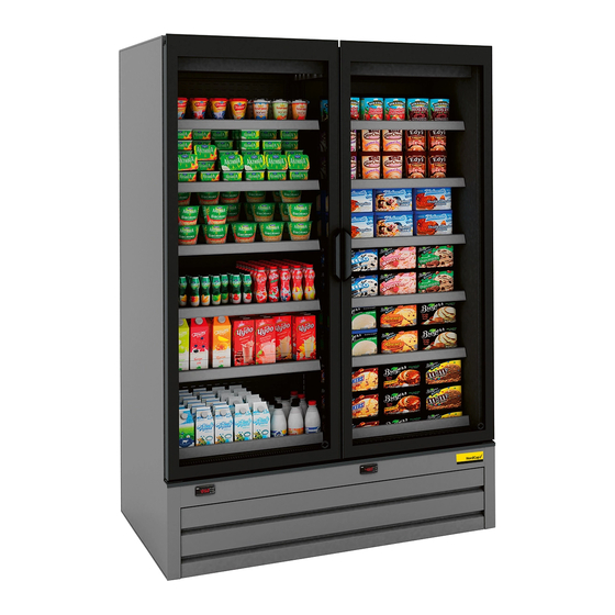
7 Cabinet Technical Details In this manual all dimensions of technical drawings are given in millimetres (mm). 7.1 Side Elevations CALLISTO DUAL Vertical Refrigerated Display Cabinets (multi decks integral) offer ideal solutions with their length options for display and sale of delicatessen, ready meals, prepacked meat products and deep frozen products. CALLISTO DUAL is a dynamic model with its stylish lines which surrounds and an ideal choice for all types of applications from hypermarkets to express stores and convenience stores. CALLISTO DUAL is designed to make the products highly visible and easily accessible to the customer. ... -
Page 25: Case Layout
7.2 Case Layout ... -
Page 26: Shelving Profiles
7.3 Shelving Profiles CALLISTO DUAL CABINETS Maximum Shelf Depth 450 Number of Shelf per Mod 5 As a standard, shelves are to positively and securely locate on their brackets whilst easy to remove and should come with 3 position brackets that allow shelves to be angled at 0˚ (horizontal), 10˚ and 20˚ from the horizontal Standard Shelf weight loading = 180 kg/m² with a deflection of no more than 5mm in any direction. ... -
Page 27: Cabinet Data Plate Descriptions
7.4 Cabinet Data Plate Descriptions No Description unit Model / Rev Cabinet Model Name/Reference & Revision ‐ Serial Number Cabinet Serial Number ‐ Cabinet Length Cabinet Length without End Wall(s) mm Date of Manufacture Production Month / Year ‐ Refrigerant Type Type of Refrigerant ‐ Refrigerant Charge Refrigerant Charging Amount g Max Design Pressure Refrigeration Design Operating Pressure bar Max Shelf Depths Maximum Allowable Shelf Depths mm Max Shelf Weight Load Maximum Allowable Shelf Weight Loadings kg Temperature Class Classification of Product Temperature in Compliance with EN ISO 23953‐2 ‐ Foaming Agent Insulation Foaming Agent ... -
Page 28: Refrigeration
Controls Control Equipment Power Consumption Watt Trim Heater Trim Heaters Power Consumption Watt Vaporizing Heaters Condense Water Vaporizing Heaters Power Consumption Watt Condensing Unit Condensing Unit Equipment Total Power Consumption Watt Nom Running Power Nominal Power Consumption Watt Nom Electrical Load Nominal Electrical Load amps Max Electrical Power Maximum Power Consumption Watt 7.5 Refrigeration Cabinet Type Refrigeration Type Refrigerants Integral CALLISTO DUAL HC R290 Incorporated Condensing Unit Designation of refrigerated display cabinet families Temperature Positive Application Temperature Negative To be used Chilled foodstuffs ... -
Page 29: Service And Maintenance
8 Service and Maintenance All servicing of the display cabinet refrigeration and electrical systems should be undertaken by qualified person(s) having suitable knowledge of electrical and refrigeration systems. Always electrically isolate the cabinet before carrying out any work that may affect or expose electrical components or moving parts (e.g.: fan blades). 8.1 Access to fans For access to fans, remove deck panels. If removing fan baffle assembly, remove screws at top of fan baffle and then lift it out using the lifting rings on the baffle. Place near the cabinet ensuring there is no strain placed on connecting cables. 8.2 Access to drainage outlets In order to access cabinet inner drainage, remove deck trays, drainage outlet can be seen. This drainage outlet pipe is placed into the Condensed Water Tray. Be sure that outlet of this drainage is placed into tray. Periodically check water level of tray. 8.3 Access to cabinet electrics and controls When working inside the electrics tray the electrical power supply must be isolated elsewhere as ... -
Page 30: Refrigeration, Electrical And Drainage Connections
8.6 Refrigeration, Electrical and Drainage Connections 8.6.1 Refrigeration There is two of reciprocating type of compressor in CALLISTO WINE 125 cabinet. CALLISTO DUAL cabinets are delivered refrigerants pre‐charged at factory. Below instructions are for servicing only. Follow instructions below before operation: Installation of the refrigeration and electrical components must be performed only by a refrigeration engineer or licensed electrician. Be sure that electric main supply is switched off. Avoid any sparks generation. Evacuate the Nitrogen (N) holding charge (approx. 3bar) carefully then evacuate the systems at least 45 minutes. Charge Refrigerant into the system. Plug ‐in the cabinet and run until setting temperature. Do not add any oil to the Compressor. Installation Instructions with Reciprocating Compressors System Evacuation It is recommended to evacuate system through liquid line and suction line at the same time. Must assure no air and water get into the system while evacuating. ... -
Page 31: Refrigerant Charge Limits
System Charging a. After evacuating, ensure system holds vacuum for 30 minutes, charge refrigerant through liquid line (NOT suction line). Refrigerant scales MUST be used on a critical charge system. Then start the compressor and run more than 3 minutes for the purpose of making each part of the compressor fully lubrication. b. If refrigerant insufficient and no more refrigerant will enter system, start the compressor and charge refrigerant through the suction line by throttling the liquid. This is done by restricting the flow of the liquid by controlling the gauge valve to ensure is not passed through the compressor. Never run the compressor for a long time, in case refrigerant is insufficient or leaking. Otherwise the compressor will be overheated and damaged. c. Refrigerant charge must be strictly adhered to section 8.6.2 ... -
Page 32: Plugs
8.6.4 Plugs Cabinet Length (mm) 1250 Plug Type FLYING TYPE / COMMANDO PLUG Voltage 230V / 50‐60Hz Terminals (Poles) 3P=6h (EN 60309‐2) Current 16A Connection Type Screw type IP Rate IP44 splash proof Enclosure Contact Material With High Conductivity Visual If the supply cord is damaged, it must be replaced by the manufacturer, its service agent or similarly qualified persons in order to avoid a hazard. ... -
Page 33: Instructions For Delivery
9 Instructions for Delivery 9.1 Transportation TEFCOLD manufactures its refrigerated cabinets suitable to be lifted using a suitable forklift. Care must be taken to place the forklift forks into appropriate areas underneath t he cabinet. Centre of gravity of the cabinets are not in the centre exactly and slightly close to the rear of the cabinets. This makes cabinets unbalanced. TEFCOLD undertakes no responsibility for damage caused by inconvenient transportation. ... -
Page 34: Installation
10 Installation 10.1 Unpacking In addition to protect cabinets from dust and humidity, they are wrapped with plastic stretch films. Remove the packaging only after having positioned the unit. Cabinets are shipped with stretch films to protect from dust and humidity. a. To examine the cabinet carefully against to probable damages which are occurred during transportation. b. In case of the cabinet is non‐damaged, to remove the cabinet and transport to the assembly section. At least two person must escort to the cabinet during transportation. c. To get out of internal parts from the cabinet and keep them in secure area until reusing. To collect and classify packing materials of the cabinet and re‐cycle them in proper way. 10.2 Minimum Clearances for Placing the Cabinet ... -
Page 35: Levelling And Door Alignment
10.3 Levelling and Door Alignment To ensure the cabinet is installed level and square, the following should be done after removing the packaging. The base plate at the bottom of the cabinet is removed. By screwing the adjustable feet at the right and left, the height of the cabinet is adjusted. The feet can be adjusted ±15mm using simple tools. For adjustment a 32mm wrench is required. Left foot adjustment Right foot adjustment Levelling process should be done every time the cabined is moved. Adjustment of the rear feet is important. Cabinet must be aligned very smooth as absolutely straight without any difference between heights of front and rear of the cabinet. ... - Page 36 The spirit level is located vertically as seen above pictures. Bubble of spirit level must be positioned in the middle if rear, front and middle feet are levelled correctly. Or, the spirit level is located horizontally as seen above pictures. Bubble of spirit level must be positioned in the middle if rear and front feet are levelled correctly. Cabinet levelling should be checked refer to the spirit level which is positioned vertically and horizontally. If the bubble of spirit level is positioned on right hand side, it means front foot is higher than rear foot. To wind down the rear foot with using proper wrench while monitoring the spirit level bubble. As a result of this misalignment, right hand door is higher than left hand door. If the bubble of spirit level is positioned on left hand side, it means rear foot is higher than front foot. To wind down the front foot with using proper wrench while monitoring the spirit level bubble. As a result of this misalignment, left hand door is higher than right hand door. Foot adjustment and levelling of the cabinet is very important application and must be done in a correct way. ...
-
Page 37: Assembly Of Shelves
10.4 Assembly of Shelves (a) (b) (c) (a) & (b) Place shelf brackets to the pilasters with an angle 90°. (c) Then place shelves on the brackets. For every shelf, two shelf brackets are delivered. Distance between two shelves can be maintained according to the products that will be placed with 25 mm slot pitch. 10.5 Assembly of Ticket Strips ... -
Page 38: Power Supply
10.6 Power Supply All power supply cables must be correctly sized by competent personnel, fitted correctly and be manufactured from materials suitable for the application. Cable connection points must be properly isolated in order to prevent sparks. All electrical equipment must be fitted with adequate Earth protection cables and all cables must be suitably identified. Before starting installation of electricity, be sure that main switch is OFF or main supply is DISCONNECTED. Electric box and main isolator switch is located on the bottom of the cabinet. Do ... -
Page 39: Probe Mapping & Display Positioning
11 Probe Mapping & Display Positioning DO NOT CHANGE PROBE LOCATION WITHOUT TEFCOLD APPROVAL! S4 PROBE (Air Off from Evaporator Coil) Placed to the back insulated panel above the evaporator, on the left end side as seen below. Probe S4 is positioned by releasable cable tie. S5 PROBE (Evaporator Coil) Placed to between aluminium fins of the evaporator, on the left hand side as seen below. DSK THERMOSTAT (Defrost End Temperature Protection; Klixon Thermostat) Placed to the back insulated panel above the evaporator, on the left end side as seen below. DSK is placed onto the bracket. ... -
Page 40: Front View
11.2 Front View 12 Dismantling and Disposal During normal operation, the appliance does not generate any environmental contamination. At the end of its life cycle, or if it is necessary to proceed to permanent decommissioning. To protect environment, please separate the parts and materials composing the display case in accordance with the waste disposal provisions in force in your country, so that they can be properly disposed of or recycled. All recyclable materials and waste should be processed and recycled by professionals, in compliance with the laws in the country in question. ... -
Page 41: Maintenance
13 Maintenance The following outlines the minimum requirements for regular maintenance. The Staff in charge of the appliance must control and respect the expiry dates for maintenance, given in the table below, calling the authorised Technical After‐sales assistance when indicated. FREQUENCY I f 3 A R M n Authorised e OPERATION o n Personnel ... - Page 42 NordCap GmbH & Co. KG Thalenhorststraße 15 D-28307 Bremen Telefon: +49 421 48557-0 Telefax: +49 421 488650 E-Mail: info(at)nordcap.de...
Need help?
Do you have a question about the CD 140 and is the answer not in the manual?
Questions and answers