
Related Manuals for nvent SPECTRACOOL

Summary of Contents for nvent SPECTRACOOL
- Page 1 SPECTRACOOL Remote Access contRol INSTRUCTION MANUAL Rev. A © 2021 nVent 89209827 P/N 89209827...
-
Page 2: Table Of Contents
Symptoms and Possible Causes - Remote Access Control Version ....................... 45 NOTE: Some of the information in this manual may not apply if a special unit was ordered. If additional drawings for a special unit are necessary, they have been inserted. Contact nVent Electrical if further information is required. -
Page 3: Introduction
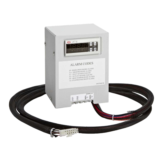
CONTROLLER STATUS INDICATION The display has numerous symbols to indicate the various controller functions such as cooling, heating, alarming, evaporator fan, and heating. Indicators (icons) are steady illuminated on screen when active. © 2021 nVent 89209827 - 3 -... - Page 4 • Steady ON while compressor is running White Evaporator Running White Electric heater ON White Primary and/or lead controller ON White Freeze control Compressor and Condenser fan OFF while illuminated White Power ON © 2021 nVent 89209827 - 4 -...
- Page 5 © 2021 nVent 89209827 - 5 -...
-
Page 6: Displaying And Changing Program Settings
This controller is equipped with a real time clock for logging the time and date of alarm activities. There are five parameters designating to the minute, hour, year, month of the year, and day of the month as illustrated in below table. © 2021 nVent 89209827 - 6 -... -
Page 7: View Alarms
No effect on function setpoint Compressor and condenser fan turns OFF for the duration of alarm. Alarm Frost alarm Evaporator coil freezes Closed clears when the outlet temperature sensor reaches 59 F © 2021 nVent 89209827 - 7 -... -
Page 8: To Reset The Alarms In Alarm History Folder
Parameter C21 controls the alarm relay output logic and can be accessed through security code “0022” in the PArF folder. Configuration Para Description 0 = normally open (NO) – factory default Alarm relay output logic 1 = normally closed (NC) © 2021 nVent 89209827 - 8 -... -
Page 9: Alarm Input Connection
Hoffman network card (RAC module). 7. Best recommendation is to configure the ACU that has Hoffman network card to be the primary one CONNECTING UNITS TOGETHER IN PRIMARY/SECONDARY MODE Figure 2: Primary-secondary network connectivity © 2021 nVent 89209827 - 9 -... -
Page 10: Lead-Lag (Ll) Mode
The two air conditioners will take turns being the lead and lag. Alternating can be done in time based or every cooling cycle and is configured with H14. CONNECTING UNITS TOGETHER IN LEAD/LAG MODE Figure 3: Lead-Lag Network Conectivity © 2021 nVent 89209827 - 10 -... -
Page 11: Air Conditioner Unit Remote Communication Features
Air conditioners that include the optional Hoffman network card (RAC module) have remote communication capabilities utilizing SNMP, Modbus TCP, EtherNet/IP, Profinet Protocol via Ethernet connection, and Modbus RTU protocol via USB connection. nVent provides Windows interface application software that is available to download free from nVent support link https://go.nvent.com/remote-access-control-support-center. -
Page 12: Using Hoffman Pc Interface Tool
Click on Read Ethernet Info button, the Ethernet information will be displayed and the Reprogram ACU button is enable To change the Ethernet configuration such as Device IP Address, Gateway IP, and Trap IP, make sure to change the • © 2021 nVent 89209827 - 12 -... -
Page 13: Ethernet Communication Mode
Refer to remote access control (RAC) Instruction Manual for configuring multiple units and with text message and email capability in Hoffman A.C. Monitor software. The remote access control Instruction Manual, P/N: 89091002 can be downloaded from nVent support center link, https://go.nvent.com/remote-access-control-support-center. - Page 14 INLET TEMP PROBE DOOR OPEN SWITCH WHT63 GROUND RESERVED OUTLET TEMP PROBE RED45 MAL-FUNCTION ALARM BLU88 RESERVED UNIT REMOTE ON/OFF RESERVED RESERVED GROUND RESERVED DATA (-) DATA (+) GROUND DATA (-) DATA (+) GROUND © 2021 nVent 89209827 - 14 -...
- Page 15 Unzip the Hoffman A.C. Monitor 3.1.0 Setup.zip file into a temporary directory. • Double click on the Hoffman A.C. Monitor 3.1.0 Setup.exe file to start the installation process. • • Click on the “Next” button when the installation window opens. © 2021 nVent 89209827 - 15 -...
- Page 16 Documents\Hoffman directory. If you don’t want the User’s Manual, uncheck the box. If it is OK, click the “Next” button. • If the default Start Menu folder “Hoffman” is OK, click the “Next” button. © 2021 nVent 89209827 - 16 -...
- Page 17 Note: If you exported a configuration file from a previous version of the application, now is the time to import the original configuration file by follow the procedure in 4.5 Importing a Configuration File on page 17. © 2021 nVent 89209827 - 17 -...
- Page 18 “IP Address” column header. The air conditioners will now be displayed in increasing IP Address order. You will see an “up arrow” to the right of the “IP Address” that indicates the increasing IP address order. © 2021 nVent 89209827 - 18 -...
- Page 19 Note: If a new fault is logged when the “ACU Faults” tab is selected, the screen will refresh and display all of the faults in descending date/time order. © 2021 nVent 89209827 - 19 -...
- Page 20 A.C. Monitor to confirm that the IP address for a given air conditioner is correct. Click the “Scan for new ACUs” button. A window will open where the Class-C network subnet to scan can be entered. © 2021 nVent 89209827 - 20 -...
- Page 21 The Secondary ACUs will need to be manually added to the configuration. 4.2 Manually adding an air conditioner to the configuration Click the “Tools” menu and select “Change Multiple ACU Configuration” from the pull-down menu. © 2021 nVent 89209827 - 21 -...
- Page 22 ID to correspond to the Secondary ACUs ID in the range of 2-4. When the ACUs are polled, the application will append the Primary/Secondary ID to the Unit ID to make tracking easier. © 2021 nVent 89209827 - 22 -...
- Page 23 Click the “Tools” menu and select “Change Multiple ACU Configuration” from the pull-down menu. Click the box to the left of the row for the desired air conditioner. All cells in the row will highlight. Press the “Delete” key. © 2021 nVent 89209827 - 23 -...
- Page 24 “Save Configuration File” button to save the configuration values from the air conditioners. If you need to change any of the air conditioner set-points, you can click the “Tools” menu and © 2021 nVent 89209827 - 24 -...
- Page 25 An existing XML configuration file can be imported into the Hoffman A.C. Monitor. Click the “Tools” menu and select “Change Multiple ACU Configuration” from the pull-down menu. and, finally, click “Import Configuration File” button. © 2021 nVent 89209827 - 25 -...
- Page 26 Click the “Tools” menu and select “Change Multiple ACU Configuration” from the pull-down menu. Then click “Export Configuration File” button. From the “Open Multiple ACU Configuration File” window, select the desired directory and file name and click “Save” button. © 2021 nVent 89209827 - 26 -...
- Page 27 IP Address and SNMP Community will be set in the corresponding fields in the Single Hoffman A.C. Monitor tab. These fields will be used to communicate with the air conditioner. © 2021 nVent 89209827 - 27 -...
- Page 28 “Device ID” field and click on the “Enable Comm” button. The text on the “Enable Comm” button will change to “Disable Comm” when communications with the ACU is established. Click on the “Disable Comm” button to stop monitoring a single ACU. © 2021 nVent 89209827 - 28 -...
- Page 29 The Hoffman A.C. Monitor can be configured to automatically start polling the air conditioners in the Multiple ACU mode when the application is started, and/or to enable logging of faults into an alarm file. © 2021 nVent 89209827 - 29 -...
- Page 30 6.1. Enabling Hoffman A.C. Monitor Auto-Start and/or Alarm File Logging © 2021 nVent 89209827 - 30 -...
- Page 31 If Excel is installed, Excel will be launched to open the XML archive fault log file. The current faults in the display will be cleared. The Alarm File is XML formatted and can be read by Microsoft Excel. © 2021 nVent 89209827...
- Page 32 Windows and set the application’s language to English, German, Mexican Spanish, Polish, Russian, or Simplified Chinese. If the PC is configured for any other language, the application’s language will configure to English. © 2021 nVent 89209827 - 32 -...
- Page 33 The Hoffman A.C. Monitor can be configured to log sensor data from one or more ACUs into a sensor data file. The sensor data file can then be opened in Excel for analysis. 8.1. Configuring an ACU for Data Logging © 2021 nVent 89209827 - 33 -...
- Page 34 24 hour version of the current time. If Excel is installed, Excel will be launched to open the archive data log file. The current sensor data in the display will be cleared. The data log file is XML formatted and can be read by Microsoft Excel. © 2021 nVent 89209827 - 34 -...
- Page 35 ACU. The date and time from the PC running the Hoffman A.C Monitor at the time of the poll is listed in column A. You can sort the data by clicking on the arrow next to the column heading. © 2021 nVent 89209827 - 35 -...
- Page 36 If a title on the top of the chart is desired, click on the chart, click on “Layout”, click on “Chart Title”, click on “Above Chart”. A text box will appear above the chart. Click on the text and change it to “Compressor 6”. © 2021 nVent 89209827 - 36 -...
- Page 37 The above resulting chart had the ACU Cooling Setpoint set to 80F and the Cooling Differential set to 10F. From this graph, one can see that the corresponding Inlet Temperature varied between 80F and 90F. © 2021 nVent 89209827 - 37 -...
-
Page 38: Instructions For Configuring Email Or Sms When There Is An Acu Fault
3. Execute Hoffman A.C Monitor SW 4. Click on “Tools” then “change Multiple ACU Configuration” then “Import Configuration File”. 5. When the window opens, select the ACUconfig.xml file and click on the “Open” button. © 2021 nVent 89209827 - 38 -... - Page 39 7. When the window opens, click on the “OK” button. 8. To add new A/C from the network, click the new cell of “Group” and then enter the name of the A/C unit © 2021 nVent 89209827 - 39 -...
- Page 40 If your mobile is with AT&T, it is likely “%7632031233@txt.att.net”. If you have Verizon for your carrier then “%7632031233@vtext.com”. When you are finished, click on “Save Configuration File” then “Enable Polling” © 2021 nVent 89209827 - 40 -...
- Page 41 Enter the SMTP email server’s port number in the “SMTP Port” field. The SMTP email server’s port number is usually 25, but may be different. Enter the email address that you would like in the “From:” field of the ACU Fault email in the © 2021 nVent 89209827 - 41 -...
- Page 42 SMTP email server when the Hoffman A.C. Monitor tries to send a fault email, you will see a popup window describing the problem. Correct the SMTP configuration problem, and then enable polling. © 2021 nVent 89209827 - 42 -...
- Page 43 NOTES © 2021 nVent 89209827 - 43 -...
-
Page 44: Basic Air Conditioning Trouble Shooting Check List - Remote Access Control Version
• Defective motor capacitor(s) 7. Carefully check the compressor for proper operation - motor should cause slight vibration and the outer case of the compressor should be warm. Is the compressor showing signs of this? © 2021 nVent 89209827 - 44 -... -
Page 45: Symptoms And Possible Causes - Remote Access Control Version
Unit blows breakers Short in system Drain plugged Drain tube kinked Getting water in enclosure Enclosure not sealed (allowing humidity in) Mounting gasket damaged For additional technical information, contact nVent Electrical at 800-896-2665.z © 2021 nVent 89209827 - 45 -... - Page 46 NOTES © 2021 nVent 89209827 - 46 -...
- Page 47 NOTES © 2021 nVent 89209827 - 47 -...
- Page 48 Rev. A © 2021 nVent 89209827 P/N 89209827...
Need help?
Do you have a question about the SPECTRACOOL and is the answer not in the manual?
Questions and answers