
Related Manuals for nvent SPECTRACOOL

Summary of Contents for nvent SPECTRACOOL
- Page 1 SPECTRACOOL Remote Access contRol INSTRUCTION MANUAL Rev. M © 2018 nVent 89091001 P/N 89091002...
-
Page 2: Table Of Contents
Symptoms and Possible Causes - Remote Access Control Version .......................35 NOTE: Some of the information in this manual may not apply if a special unit was ordered. If additional drawings for a special unit are necessary, they have been inserted. Contact nVent Electrical if further information is required. -
Page 3: Introduction
The 3 alpha-numeric characters further describe alarms and show the cabinet temperature by default. NOTE: The Slim Fit air conditioners DO NOT come standard with a heating option. © 2018 nVent 89091001 - 3 -... -
Page 4: Displaying And Changing Program Variables
35 C 20 C to 55 C Cooling differential Door Open and/or smoke detected 4 or 28 ALARM PARAMETERS Parameter Description Default Value Range High Temperature Alarm 55 C Low Temperature Alarm 14 C © 2018 nVent 89091001 - 4 -... -
Page 5: Operating Parameters
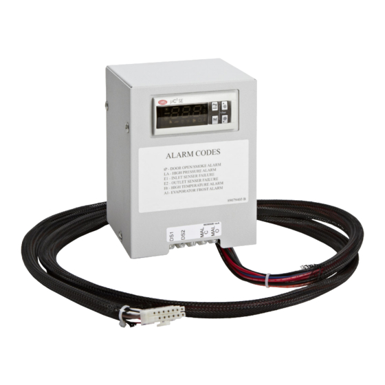
There are eleven possible non-latching alarm conditions detectable by the controller and are indicated on the controller display. All alarms can also be accessed through the Ethernet and USB connections with the optional remote access communication board. © 2018 nVent 89091001 - 5 -... -
Page 6: Master-Slave Capabilty (Optional)
NOTE 7: Set parameter h25 (number of units) of each unit to the same value, for example, h25 = 2 if only two units are connected in a group, h25 = 3 if three units are in a group and h25 = 4 if four units are in a group. © 2018 nVent 89091001... -
Page 7: Master-Slave Alarm Input Connection
SOFTWARE AND CONFIGURATION FILE DOWNLOADS The PC Interface Tool, MIB file, Coil_Register file, EDS file or EtherNet_IP Object file, and GSDML file can be downloaded from http://www.nventprotect.com/en/na/Product-Enclosure-Cooling-Heating © 2018 nVent 89091001 - 7 -... -
Page 8: Using The Pc Interface Tool
Each unit has two community strings. One is a Read/Write community string (defaulted to ‘private’) that can be changed by the customer (must be 4 to 8 characters long). The other is a Read-Only community string (‘public’) and cannot be changed. © 2018 nVent 89091001 - 8 -... -
Page 9: The Hoffman A.c. Monitor
Unzip the Hoffman A.C. Monitor 3.1.0 Setup.zip file into a temporary directory. • Double click on the Hoffman A.C. Monitor 3.1.0 Setup.exe file to start the installation process. • Click on the “Next” button when the installation window opens. © 2018 nVent 89091001 - 9 -... - Page 10 Documents\Hoffman directory. If you don’t want the User’s Manual, uncheck the box. If it is OK, click the “Next” button. • If the default Start Menu folder “Hoffman” is OK, click the “Next” button. © 2018 nVent 89091001 - 10 -...
- Page 11 Click on the “Finish” button when the installation completes. • The Hoffman A.C. Monitor application is now ready to use. You can start the program by clicking “Start->All Programs->Hoffman->Hoffman A.C. Monitor” menu, or on the Desktop icon. © 2018 nVent 89091001 - 11 -...
-
Page 12: Running The Hoffman A.c. Monitor
Configuration File on page 21. The application will start with the “Single Hoffman A.C. Monitor” tab selected. Click on the “Multiple Hoffman A.C. Monitor” tab to select the Multiple Hoffman A.C. Monitor mode. © 2018 nVent 89091001 - 12 -... -
Page 13: Controlling The Hoffman A.c. Monitor Display
Note: If you would like the current display order to be permanent, Click on “Tools” menu, then “Change Multiple ACU Configuration” in the pull-down menu, and, finally, click on the “Save Configuration File” button. © 2018 nVent 89091001 - 13 -... -
Page 14: Displaying Acu Faults
Note: If a new fault is logged when the “ACU Faults” tab is selected, the screen will refresh and display all of the faults in descending date/time order. © 2018 nVent 89091001 - 14 -... -
Page 15: Configuring The Hoffman A.c. Monitor
A.C. Monitor to confirm that the IP address for a given air conditioner is correct. Click the “Scan for new ACUs” button. A window will open where the Class-C network subnet to scan can be entered. © 2018 nVent 89091001 - 15 -... -
Page 16: Manually Adding An Air Conditioner To The Configuration
The Slave ACUs will need to be manually added to the configuration. 4.2 Manually adding an air conditioner to the configuration Click the “Tools” menu and select “Change Multiple ACU Configuration” from the pull-down menu. © 2018 nVent 89091001 - 16 -... - Page 17 SNMP Community to the factory default value of “private”, or to the customized value. When you have finished entering the Community, press the “Enter” key. © 2018 nVent 89091001 - 17 -...
- Page 18 Configuration File” button to save the current air conditioner configuration. Click the “Yes” button to save the current Hoffman A.C. Monitor configuration. Repeat the above steps to add additional air conditioners to the configuration. © 2018 nVent 89091001 - 18 -...
-
Page 19: Deleting An Air Conditioner From The Configuration
Note: You can hold the “CTRL” key on your keyboard down and click on multiple ACUs. When you press the “Delete” key the application will ask if it is OK to delete each of the selected air conditioners. © 2018 nVent 89091001 - 19 -... -
Page 20: Modifying The Air Conditioner Settings
Note: The IP address and SNMP Community settings cannot be changed from the Multiple Hoffman A.C. Monitor tab. You can use the Single ACU Ethernet Info tab to change the IP address or SNMP Community settings. © 2018 nVent 89091001 - 20 -... -
Page 21: Importing A Configuration File
Use the “Open Multiple ACU Configuration File” window to find and select the XML configuration file to import, and select “Open” button. You must click the “Save Configuration File” button to make the imported configuration the permanent configuration. © 2018 nVent 89091001 - 21 -... -
Page 22: Exporting A Configuration File
Note: You can use the Export/Import tools to copy the Multiple ACU Configuration from one PC to another. Note: You can export the Multiple ACU Configuration file, edit it using an XML editor, and, finally, re-import it. © 2018 nVent 89091001 - 22 -... -
Page 23: Changing The Acu Ip Address Or Snmp Community Setting
Hoffman A.C. Monitor tab. You can use the Single ACU Ethernet Info tab to change the IP address or SNMP Community settings. Note: You will need to modify the configuration in the Multiple Hoffman A.C. Monitor tab to correspond to the new network configuration for the air conditioner. © 2018 nVent 89091001 - 23 -... -
Page 24: Monitoring Or Configuring A Single Acu
The Master/Slave configuration and the Door Switch Polarity can be changed using the same method. Note: the Temperature setpoints can only be changed in 0.1 degree steps. There is an upper and lower limit to all of the temperature settings. © 2018 nVent 89091001 - 24 -... -
Page 25: Enabling Hoffman A.c. Monitor Auto-Start And/Or Alarm File Logging
The Hoffman A.C. Monitor can be configured to automatically start polling the air conditioners in the Multiple ACU mode when the application is started, and/or to enable logging of faults into an alarm file. 6.1 Enabling Hoffman A.C. Monitor Auto-Start and/or Alarm File Logging © 2018 nVent 89091001 - 25 -... -
Page 26: Exporting The Alarm File To Microsoft Excel
If Excel is installed, Excel will be launched to open the XML archive fault log file. The current faults in the display will be cleared. The Alarm File is XML formatted and can be read by Microsoft Excel. © 2018 nVent 89091001... - Page 27 For example, row 9 shows an ACU that failed to respond to an SNMP poll, but had previously responded. Row 2 shows a high pressure fault and row 4 shows a door open fault. © 2018 nVent 89091001 - 27 -...
-
Page 28: Changing The Hoffman A.c. Monitor Language
You can override the detected language by clicking “File”and selecting “Language Settings”. A window will open as shown above. Select “Manually Configure Language” button. A pull-down menu will be displayed showing the possible languages. Select the desired language and click “OK”. © 2018 nVent 89091001 - 28 -... -
Page 29: Hoffman A.c. Monitor Data Logging
ACU for data logging. When clicking on “Enable Polling” button, the sensor data for each ACU that was configured for data logging will be stored in an XML file. © 2018 nVent 89091001 - 29 -... -
Page 30: Exporting The Sensor Data To Microsoft Excel
The current sensor data in the display will be cleared. The data log file is XML formatted and can be read by Microsoft Excel. A window will open as shown above. Click OK button. A window will open as shown above. Click OK button. © 2018 nVent 89091001 - 30 -... -
Page 31: Graphing The Temperature Sensor Data In Microsoft Excel
In order to create a temperature sensor graph, click on the Unit ID arrow to sort all of the data for each ACU into adjacent cells. Select the Enc_Air_In and Enc_Air_Out cells for a single ACU. Click on “Insert”, “Line”, and select the 2D Line chart. © 2018 nVent 89091001 - 31 -... - Page 32 The above resulting chart had the ACU Cooling Setpoint set to 80F and the Cooling Differential set to 10F. From this graph, one can see that the corresponding Inlet Temperature varied between 80F and 90F. © 2018 nVent 89091001 - 32 -...
- Page 33 NOTES © 2018 nVent 89091001 - 33 -...
-
Page 34: Basic Air Conditioning Trouble Shooting Check List - Remote Access Control Version
6. The compressor and the condenser (Ambient or “HOT” air) impeller(s) should turn on. Is there adequate airflow? YES, proceed to step 7. NO, possible problem: » Open motor winding(s) » Stuck impeller(s) Repair or Replace » Obstructed wheel(s) defective part » Defective motor capacitor(s) © 2018 nVent 89091001 - 34 -... -
Page 35: Symptoms And Possible Causes - Remote Access Control Version
Unit blows breakers Short in system Drain plugged Drain tube kinked Getting water in enclosure Enclosure not sealed (allowing humidity in) Mounting gasket damaged For additional technical information, contact nVent Electrical at 800-896-2665.z © 2018 nVent 89091001 - 35 -... - Page 36 Rev. M © 2018 nVent 89091001 P/N 89091002...
Need help?
Do you have a question about the SPECTRACOOL and is the answer not in the manual?
Questions and answers