Table of Contents
Advertisement
Quick Links
SINUMERIK
SINUMERIK ONE
ONE MCP Part 2: MCP 2400
Equipment Manual
Valid for:
Control system
SINUMERIK ONE
SINUMERIK 840D sl/840DE sl
08/2023
A5E50324707B AB
Hardware change
information
Fundamental safety
instructions
Overview
Dimension drawings
Operator control and
display elements
Technical data
1
2
3
4
5
6
Advertisement
Table of Contents

Subscribe to Our Youtube Channel
Related Manuals for Siemens SINUMERIK ONE MCP 2400


Summary of Contents for Siemens SINUMERIK ONE MCP 2400
- Page 1 Hardware change information Fundamental safety instructions Overview SINUMERIK Dimension drawings SINUMERIK ONE ONE MCP Part 2: MCP 2400 Operator control and display elements Technical data Equipment Manual Valid for: Control system SINUMERIK ONE SINUMERIK 840D sl/840DE sl 08/2023 A5E50324707B AB...
- Page 2 Note the following: WARNING Siemens products may only be used for the applications described in the catalog and in the relevant technical documentation. If products and components from other manufacturers are used, these must be recommended or approved by Siemens. Proper transport, storage, installation, assembly, commissioning, operation and maintenance are required to ensure that the products operate safely and without any problems.
-
Page 3: Table Of Contents
Table of contents Hardware change information ......................5 Document changes to Edition 07/2020................. 5 Fundamental safety instructions......................7 General safety instructions....................7 Equipment damage due to electric fields or electrostatic discharge ........11 Warranty and liability for application examples ..............11 Cybersecurity information .................... - Page 4 Table of contents ONE MCP Part 2: MCP 2400 Equipment Manual, 08/2023, A5E50324707B AB...
-
Page 5: Hardware Change Information
Hardware change information Document changes to Edition 07/2020 New features Title Changes compared to Edition 07/2020 Status Owner Configuration New topic added to the "Operator controls and display (Page 20) elements" chapter ... - Page 6 Hardware change information 1.1 Document changes to Edition 07/2020 ONE MCP Part 2: MCP 2400 Equipment Manual, 08/2023, A5E50324707B AB...
-
Page 7: Fundamental Safety Instructions
Fundamental safety instructions General safety instructions WARNING Electric shock and danger to life due to other energy sources Touching live components can result in death or severe injury. • Only work on electrical devices when you are qualified for this job. •... - Page 8 Fundamental safety instructions 2.1 General safety instructions WARNING Electric shock due to equipment damage Improper handling may cause damage to equipment. For damaged devices, hazardous voltages can be present at the enclosure or at exposed components; if touched, this can result in death or severe injury.
- Page 9 • Therefore, if you move closer than 20 cm to the components, be sure to switch off radio devices, cellphones or WLAN devices. • Use the "SIEMENS Industry Online Support App" or a QR code scanner only on equipment that has already been switched off.
- Page 10 Fundamental safety instructions 2.1 General safety instructions NOTICE Overheating due to inadmissible mounting position The device may overheat and therefore be damaged if mounted in an inadmissible position. • Only operate the device in admissible mounting positions. WARNING Unexpected movement of machines caused by inactive safety functions Inactive or non-adapted safety functions can trigger unexpected machine movements that may result in serious injury or death.
-
Page 11: Equipment Damage Due To Electric Fields Or Electrostatic Discharge
In order to protect plants, systems, machines and networks against cyber threats, it is necessary to implement – and continuously maintain – a holistic, state-of-the-art industrial cybersecurity concept. Siemens’ products and solutions constitute one element of such a concept. Customers are responsible for preventing unauthorized access to their plants, systems, machines and networks. - Page 12 Siemens’ products and solutions undergo continuous development to make them more secure. Siemens strongly recommends that product updates are applied as soon as they are available and that the latest product versions are used. Use of product versions that are no longer supported, and failure to apply the latest updates may increase customer’s exposure...
-
Page 13: Residual Risks Of Power Drive Systems
Fundamental safety instructions 2.5 Residual risks of power drive systems Residual risks of power drive systems When assessing the machine or system-related risk in accordance with the respective local regulations (e.g. EC Machinery Directive), the machine manufacturer or system integrator must take into account the following residual risks emanating from the control and drive components of a drive system: 1. - Page 14 Fundamental safety instructions 2.5 Residual risks of power drive systems 6. Influence of network-connected and wireless communications systems, e.g. ripple-control transmitters or data communication via the network or mobile radio, WLAN or Bluetooth. 7. Motors for use in potentially explosive areas: When moving components such as bearings become worn, this can cause enclosure components to exhibit unexpectedly high temperatures during operation, creating a hazard in areas with a potentially explosive atmosphere.
-
Page 15: Overview
Overview This manual describes the specific properties of the SINUMERIK ONE MCP 2400 machine control panel. The documentation is always structured in 2 parts. Part 1 contains general information that applies to all machine control panels. Part 2 covers specifics of individual machine control panels. - Page 16 Overview ONE MCP Part 2: MCP 2400 Equipment Manual, 08/2023, A5E50324707B AB...
-
Page 17: Dimension Drawings
Dimension drawings Figure 4-1 Front, rear and side view of MCP 2400 (all specifications in mm) The installation clearance for the MCP is 55 mm. ONE MCP Part 2: MCP 2400 Equipment Manual, 08/2023, A5E50324707B AB... - Page 18 Dimension drawings Panel cutout The MCP 2400 is secured using 16 M5 nuts. The tightening torque is 1.5 Nm. Use spring elements in addition to the M5 nuts. In the sealing area Figure 4-2 Panel cutout of MCP 2400 (all specifications in mm) ONE MCP Part 2: MCP 2400 Equipment Manual, 08/2023, A5E50324707B AB...
-
Page 19: Operator Control And Display Elements
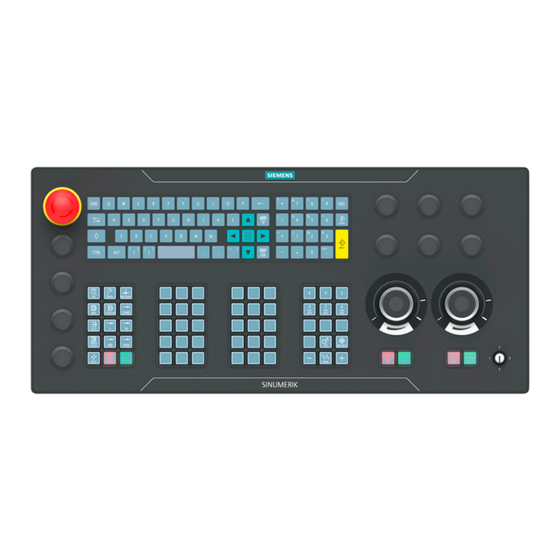
Operator control and display elements Front side Overview ① Emergency stop button ② QWERTY keyboard ③ 6x mounting space for 22.5 mm elements ④ Key-operated authorization switch ⑤ Powerride 1 (feed) + keypad 4.1 ⑥ Powerride 2 (spindle) + keypad 4.2 ⑦... -
Page 20: Rear Side
Operator control and display elements 5.3 Configuration Rear side ① Protective conductor connection ② 6x mounting space for 22.5 mm elements ③ Power supply interface X10 ④ Switch S2 ⑤ Ethernet interfaces X20 port 1/ port 2 ⑥ Handwheel connections X60/ X61 ⑦... - Page 21 Operator control and display elements 5.3 Configuration Slot 4 Keypad 3 (customer keys) Slot 5 Keypad 4 (axis block) Slot 6 Powerride 1 (feed) Slot 7 Powerride 2 (spindle) Slot 8 Handwheel 1 Slot 9 Handwheel 2 Output image Slot 1 Base Slot 2 Keypad 1 (operating mode block)
- Page 22 Operator control and display elements 5.3 Configuration ONE MCP Part 2: MCP 2400 Equipment Manual, 08/2023, A5E50324707B AB...
-
Page 23: Technical Data
Technical data MCP 2400 Safety Safety class according to EN 50178 III; PELV Degree of protection according to EN Front: IP65 Keyswitch: IP54 Rear: IP00 60529 Approvals CE / UL / EAC Flame resistance UL 94 V-1 UL identifier MCPS2003-585265E-1282111AA0 Electrical data Overvoltage category Secondary circuit supplied from primary circuits up to Cat. - Page 24 Technical data MCP 2400 Temperature change Max. 30 K/h Relative humidity 5 ... 90% (without condensation) Permissible change in the relative humidity Max. 6%/h Pollution degree 2 (only use indoors) Mechanical environmental conditions Classification of the mechanical environ‐ Class 3M2 according to EN 60721-3-3 ment Vibration load during operation Frequency range: 10 –...
- Page 25 Technical data Emergency stop button Rated voltage 24 V DC Current rating, max. Current rating, min. 1 mA Switching capacity DC 13 according to EN 60947-5-1 Conditional rated short-circuit current 10 A gL/gG according to EN 60947-5-1 500 000 Note The quantitative assessment of the emergency stop safety function must be based on the B values corresponding to the used standards (e.g.
- Page 26 Technical data ONE MCP Part 2: MCP 2400 Equipment Manual, 08/2023, A5E50324707B AB...
-
Page 27: Index
Index MCP 2400 Emergency stop button, 25 Technical data, 23 Current consumption, 23 Power consumption, 23 ONE MCP Part 2: MCP 2400 Equipment Manual, 08/2023, A5E50324707B AB... - Page 28 Index ONE MCP Part 2: MCP 2400 Equipment Manual, 08/2023, A5E50324707B AB...
Need help?
Do you have a question about the SINUMERIK ONE MCP 2400 and is the answer not in the manual?
Questions and answers