Table of Contents
Advertisement
Advertisement
Table of Contents

Related Manuals for metrolite DLT-18HD

Summary of Contents for metrolite DLT-18HD
- Page 1 MODEL DLT-18HD OPERATOR'S MANUAL...
- Page 2 • • • • • metrolite • metrolite metrolite metrolite metrolite metrolite • • • • •...
- Page 3 Customer’s Name __________________________ Dealer's Name ___________________________ Address __________________________________ Address ________________________________ City, State/Prov., Code _______________________ City, State/Prov., Code _____________________ Phone Number ( _____ ) ___________________ Light Tower Model __________________________ Serial Numbers DLT-18HD ____________________ Alternator _______________________________ Serial Numbers Engine ______________________ Delivery Date ______________________________ DEALER INSPECTION REPORT SAFETY ______ Tire Pressure Checked ______ Guards/Shields Installed & Secured ______ Wheel Bolts Torqued ______ All Decals Installed & Legible...
- Page 5 SERIAL NUMBER LOCATIONS metrolite Always give your dealer the serial number of your DLT-18HD when ordering parts or requesting service or other information. The serial number plates are located where indicated. Please mark the number in the space provided for easy reference. ENGINE DLT-18HD ALTERNATOR Model DLT-18HD Serial Number Machine ___________________________ Engine ___________________________ Alternator ___________________________...
-
Page 7: Table Of Contents
TABLE OF CONTENTS SECTION DESCRIPTION PAGE Introduction ............1 Safety ..............3 2.1 General Safety ............4 2.2 Equipment Safety Guidelines ........ 5 Safety Training ............6 Safety Signs ............6 Storage Safety ............6 Preparation Safety ..........7 Installation Safety ..........8 2.8 Maintenance Safety .......... -
Page 9: Introduction
Keep this manual handy for frequent reference and so that it will be passed on to new operators or owners. Call your metrolite dealer if you need assistance, information or additional copies of this manual. MACHINE ORIENTATION - The hitch end of the light tower is the front. All electrical controls are on the left side. -
Page 11: Safety
The Safety Alert symbol identifies This Safety Alert symbol means important safety messages on your ATTENTION! BECOME ALERT! metrolite light tower and in the YOUR SAFETY IS INVOLVED! manual. When you see this symbol, be alert to the possibility of personal injury death. -
Page 12: General Safety
2.1 GENERAL SAFETY YOU are responsible for the SAFE operation • Read and understand the and maintenance of your metrolite light tower. Operator's Manual and all safe- YOU must en-sure that you and anyone else who is ty signs before supplying pow-... -
Page 13: Equipment Safety Guidelines
2.2 EQUIPMENT SAFETY GUIDELINES • Safety of the operator and bystanders is one of • In addition to the design and configuration of this the main concerns in designing and developing a implement, including Safety Signs and Safety machine. However, every year many accidents oc- Equipment, hazard control and accident preven- cur which could have been avoided by a few sec- tion are dependent upon the awareness, concern, onds of thought and a more careful approach to... -
Page 14: Safety Training
2.3 SAFETY TRAINING 2.4 SAFETY SIGNS • Safety is a primary concern in the design and man- • Keep safety signs clean and legible at all times. ufacture of our products. Unfortunately, our efforts • Replace safety signs that are missing or have be- to provide safe equipment can be wiped out by a come illegible. -
Page 15: Preparation Safety
2.7 INSTALLATION SAFETY 2.6 PREPARATION • Review layout of the worksite. Position light • Never operate the light tower and auxiliary tower where it can provide maximum equipment until you have read and complete- illumination with minimal interference with the ly understand this manual, the auxiliary equip- access and opera-tion of other equipment. -
Page 16: Maintenance Safety
2.9 HYDRAULIC SAFETY 2.8 MAINTENANCE SAFETY • Make sure that all the components in the pump • Read and understand all the information contained system are kept in good condition and are clean. in the Operator's Manual regarding operating, ser- • Before applying pressure to the system, make sure vicing, adjusting, maintaining and repairing. all components are tight, and that lines, hoses and •... -
Page 17: Operating Safety
• Do not park light tower on a steep slope. • Replace all worn or failed components • Be sure that any necessary signs, reflectors and immediate-ly with metrolite approved parts. lights required by law are in proper place and are • Install and secure all guards before operating. clearly visible to oncoming and overtaking traffic. • Keep hands, feet, hair and clothing away •... -
Page 18: Diesel Engine Safety
2.16 DIESEL ENGINE SAFETY BEFORE STARTING ENGINE, READ AND UNDER- STAND THE OPERATING AND MAINTENANCE IN- • DO NOT run engine with air cleaner or air cleaner STRUCTIONS THAT CAME WITH YOUR ENGINE. cover removed. WARNING: DO NOT WARNING: DO • DO NOT run engine in an enclosed area. Exhaust • ALWAYS Disconnect the negative wire from the gases contain carbon monoxide, an odorless and battery terminal before servicing engine to prevent deadly poison. -
Page 19: Sign-Off Form
Safety Standards specified by the American Society of Agricultural and Biological Engineers (ASABE) and the Occupational Safety and Health Administration (OSHA). Anyone who will be operating and/or maintaining a Metrolite built machine must read and clearly understand ALL Safety, Operating and Maintenance information presented in this manual. -
Page 21: Safety Sign Locations
SAFETY SIGN LOCATIONS The types of safety signs and locations on the equipment are shown in the illustrations that follow. Good safety requires that you familiarize yourself with the various Safety Signs, the type of warning and the area, or particu- lar function related to that area, that requires your SAFETY AWARENESS. - Page 22 The types of safety signs and locations on the equipment are shown in the illustrations that follow. Good safety requires that you familiarize yourself with the various Safety Signs, the type of warning and the area, or particu- lar function related to that area, that requires your SAFETY AWARENESS. • Think SAFETY! Work SAFELY! REMEMBER - If Safety Signs have been damaged, removed, become illegible or parts replaced without safety signs, new signs must be applied.
-
Page 23: Operation
Metrolite light tower will provide many years of dependent upon the awareness, concern, and trouble-free service. prudence of personnel involved in the operation, transport, maintenance and storage of equipment or in the use of facilities. -
Page 24: Machine Components
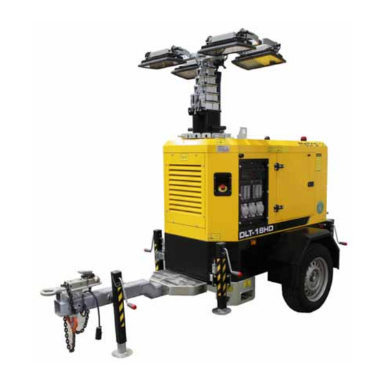
4.2 MACHINE COMPONENTS The Metrolite light tower is a diesel engine Outriggers are located on each corner of the frame powering an alternator to generate electricity. This and are pinned in position both extended and retract- electricity is used to power the LED lights on the ed. -
Page 26: Machine Break-In
Although there are no operational restrictions on the Safe and efficient operation of your new light tower re- Metrolite light tower when used for the first time, quires that each operator reads and follows all safety it is recommended that the following mechanical... -
Page 27: Controls
4.5 CONTROLS It is recommended that all operators read the D e e p Sea Electronics module manual to learn how to operate and navigate through the module features. Knowl-edge and understanding of this control module allows the operator to monitor and set a variety of engine and machine parameters. - Page 28 3. Switches: a. Mast Position: This 3 position spring-loaded to centre- neutral rocker switch controls the flow of oil to the hydraulic cylinders on the mast. Depress and hold the top portion of the switch to raise the mast. Depress and hold the bottom portion of the switch to lower the mast.
- Page 29 5. Red Emergency Stop: This red switch is connected to a microswitch that disengages the power to the engine and machine electrical systems. Depress switch and the machine will stop. Turn the switch 1/4 turn to re-lease the switch and it will pop out and the unit can operate.
-
Page 30: Machine Preparation
4.6 MACHINE PREPARATION 4. Diesel Fuel: Check the fuel level every day to prevent 4.6.1 MECHANICAL PREPARATION: running out. A red light on top of the frame flashes when the fuel level drops to a pre-set Batteries: level. Since the unit can run for Batteries are an integral component in the suc- 55 to 60 hours at 75% engine cessful operation of the light tower and must be... - Page 31 4.6.2 HANDLING: The machine is designed with features that al- low it to be easily and conveniently moved, posi- tioned and transported. Three features are available to assist in handling: Lifting with hoist: A bracket on the top of the machine is positioned at the machine centre of gravity.
- Page 32 4.6.3 ELECTRICAL PREPARATION: Every operator should review the operator's manuals from the Victron. Deep Sea Electronics and alterna- tor manufacturers provided in the document package. Follow the detailed instructions in each manual: Connect the neutral point of the generator set to the machine ground.
- Page 33 GSM, GPS and combined GSM & GPS Antenna’s are In case of an emergency because of engine, hydrau- available as standard on your DLT-18HD light tower. lic pump or electrical failure, the operator must lower the mast using the bypass valve of the solenoid valve You can easily download installation instruction from: on the hydraulic pump.
-
Page 34: Operation
Clear the area of bystanders, especially • Do not stand or climb on machine when running. small children. Keep others off. • Replace all worn or failed components • Keep the working area clean and dry. immedi-ately with metrolite approved parts. • Review safety instructions annually. • Install and secure all guards before operating. • Keep hands, feet, hair and clothing away from moving parts. Follow this procedure when using the light tower: Move unit to work site and unhook (refer to Transport Section). - Page 35 5. Operating Mode: The machine is designed to be operated in 2 dif- ferent ways to allow the operator to set the operat- ing mode appropriate for the application. Review the options and set appropriate for the application: a. Continuous Run/Lights. b.
- Page 36 d. Turn the mast to the desired angle by retract- ing the lock pin, turn the mast to the required lamp angle (use the handles on each side of the mast) and release the lock pin. FIG. 14 MAST ANGLE e. Release the red emergency stop switch by turning it 1/4 turn clockwise. FIG. 15 EMERGENCY STOP BUTTON Open the passenger side canopy door and turn the main battery disconnect switch ‘ON’...
- Page 37 Move to the driver side of the machine, check and ensure all the breakers are in the ‘on’ position. FIG. 17 DRIVER'S SIDE Use the rocker switch to raise the mast. Do not raise mast if there are overhead electrical power lines.
- Page 38 11. Operating Hints: a. Raising the Mast: Use the UP and DOWN arrows on the con- trol panel to raise and lower the mast Stay away from overhead power lines to avoid electrocution. Arrows Light Mast - Lowered Raising Raised FIG.
- Page 39 b. Extend outrigger arms and pin. Lower jacks to level frame. Use bubbles in spirit levels when levelling frame. Outriggers Spirit Levels FIG. 20 LEVELLING...
-
Page 40: Storage
4.8 STORAGE STORAGE SAFETY • Store the light tower on a firm level surface. • If required, make sure the unit is firmly blocked • Make certain that all mechanical locks and jacks are safely and positively connected before storing. • Store away from areas of human activity. • Do not allow children to play on or around the stored light tower. 4.10.1 PLACING IN STORAGE 4.10.2 REMOVING FROM STORAGE At the end of the season, the machine should be thor- When preparing to use the machine at the start of the oughly inspected and prepared for storage. Repair or season, follow this procedure:... -
Page 41: Transport
Slow down for corners and rough surface conditions. Metrolite DLT-18HD light towers are designed and equipped to be towed on public roadways by vehicles with sufficient weight and braking capability. - Page 42 d. Attach safety chains while crossing them un- der the hitch. Safety Chain - Attached e. Attach wiring harness terminal. Wiring Harness - Connected Raise the hitch jack into its fully UP position. g. Rotate jack and pin in its horizontal position. h. Secure jack handle with its retainer. Reverse this procedure when unhooking. Jack Rotated/Handle Secured • Check that all required lights are clean and no bulbs are burned out.
-
Page 43: Service And Maintenance
SERVICE AND MAINTENANCE MAINTENANCE SAFETY • Read and understand all the information con- tained in the Operator's Manual regarding op- erating, servicing, adjusting, maintaining and SERVICE repairing. Turn machine OFF, shut down and lock out • 5.1.1 FLUIDS AND LUBRICANTS power supply, relieve hydraulic pressure and wait for all moving parts to stop before ser- Grease:... - Page 44 5.1.3 SERVICING INTERVALS 8 Hours or Daily Check engine fluid levels: a. Fuel b. Crankcase oil c. Coolant Fuel Cap Engine FIG. 24 FLUID LEVELS 2. Remove dust from air cleaner flapper. FIG. 25 AIR CLEANER...
- Page 45 75 Hours Change break-in engine oil and oil filter. This ser- vice item only must be done once when unit is new. Then follow the service schedule outlined in the engine manufacturer's manual. Engine 500 Hours 1. Change engine oil 2.
- Page 46 1000 Hours or Annually Change fuel filter. 2. Change oil filter. 3. Change fuel filter. 4. Change fuel screen filter. 5. Change air filter. FIG. 28 FUEL FILTER 2000 Hours or Bi-Annually Change hydraulic system oil. FIG. 29 HYDRAULIC PUMP...
- Page 47 5.1.4 SERVICE RECORD See Lubrication and Maintenance sections for details of service. Copy this page to continue record. ACTION CODE: CL CLEAN CK CHECK G GREASE R REPACK CH CHANGE Maintenance Hours Serviced by 8 Hours or Daily CK Engine Fluid Levels CL Air Cleaner Flapper 75 Hours CH Break-In Engine Oil and Filter As Required...
-
Page 48: Maintenance
5.2 MAINTENANCE By following a careful service and maintenance pro- gram on your machine, you will enjoy many years of trouble-free use. 5.2.2 ELECTRIC SYSTEM INSPECTION 5.2.1 HYDRAULIC MAINTENANCE Electricity provides power to all systems on the light A hydraulic system provides power to raise the mast. tower. - Page 49 5.2.3 CLEANING AIR CLEANER 1. Review the operator's manual for the engine. 2. Place all controls in the OFF or neutral position. 3. Turn OFF battery disconnect. 4. Open engine door. 5. Remove cover over air cleaner. 6. Remove the filter from the air cleaner. 7.
- Page 50 5.2.4 CHANGING ENGINE OIL AND FILTER 1. Review the operator's manual for the engine. 2. Place all controls in the OFF or neutral position. 3. Turn OFF battery disconnect. 4. Open engine door. 5. Allow the engine to cool before changing the oil. Hot oil can cause burns if it contacts exposed skin. It is best to change oil while the engine is warm to keep any contaminants in suspension.
- Page 51 5.2.5 CHANGING ENGINE FUEL FILTER Review the operator's manual for the engine. Place all controls in the OFF or neutral position. Turn OFF battery disconnect. Open engine door. Allow the engine to cool before changing the fuel filter. Hot fuel can cause burns if it contacts ex-posed skin. It is best to change filter while the engine is warm to keep any contaminants in suspension.
-
Page 53: Trouble Shooting
In the following section, we have listed many of the problems, causes and solutions to the problems that you may encounter. If you encounter a problem Metrolite dealer or the factory. Before you call, please have this Operator’s Manual from your machine ready. - Page 54 No light (lamp). Faulty lamp connection. Check that lamp is tight in socket. Check connections inside junction boxes on light fixtures and tower. Plug connection at fixture is loose Repair or replace the plug connection. or damaged. Lamp broken or burned out. Check the following: • broken arc tube or outer lamp jacket • broken or loose components in lamp envelope • Blackening or deposits inside lamp tube Circuit breaker turned on.
-
Page 55: Specifications
SPECIFICATIONS 2. DATA SHEET 7 .1 MECHANICAL DLT-18HD is a lighting tower for heavy duty application, please see data sheet below and dimensional as well: Engine Model Kohler KDI 1903 M Speed 1800 rpm Coolant Liquid Rated frequency 60 Hz Emissions Tier 4 –... - Page 56 3. DIMENSIONAL...
-
Page 57: Bolt Torque
7 .2 BOLT TORQUE CHECKING BOLT TORQUE The tables shown below give correct torque values for various bolts and capscrews. Tighten all bolts to the torques specified in chart unless otherwise noted. Check tightness of bolts periodically, using bolt torque chart as a guide. Replace hardware with the same strength bolt. -
Page 58: Hydraulic Fitting Torque
7 .3 HYDRAULIC FITTING TORQUE TIGHTENING O-RING FITTINGS * Tube Recommended Nut Size Torque Inspect O-ring and seat for dirt or obvious defects. Size Turns To Tighten Across Value* (After Finger Flats 2. On angle fittings, back the lock nut off until Tightening) washer bottoms out at top of groove. -
Page 59: Electrical Schematic
7 .4 ELECTRICAL SCHEMATIC 4. ELETRICAL DRAWING... -
Page 63: Index
INDEX PAGE PAGE Introduction ............1 Safety ..............3 Battery Safety ..........8 Diesel Engine Safety ........10 Electrical Safety ..........9 Equipment Safety Guidelines ......5 General Safety ..........4 Operation ............15 Hydraulic Safety ..........8 Controls ............19 Installation Safety ..........8 To the New Operator or Owner ....15 Lock-Out Tag-Out Safety .......8 Machine Components ........16 Maintenance Safety ........8... - Page 66 Phone: 1 (866) 918-6976 service@axiomequipmentgroup.com PRINTED IN CANADA REVISION DATE: SEPTEMBER 2023 PART NUMBER: 21687...
Need help?
Do you have a question about the DLT-18HD and is the answer not in the manual?
Questions and answers