Table of Contents
Advertisement
Quick Links
Instruction Manual
CVS Type 630 HP
Regulators and
Relief Valves
Introduction
Please note: These regulators and relief valves must
be installed, operated and maintained in accordance
with CVS instructions and all applicable federal,
provincial, state and local codes, laws, rules, and
regulations.
The CVS 630 HP Series consists of a high pressure
reducing regulator, and Type CVS 630R relief valve.
These regulators and relief valves are furnished in
either spring-loaded or pressure-loaded construction
with 1 or 2 inch NPT screwed end connections and
ASME Class 150 through 600 RF Flanged end
connections.
Pressure loaded Type 630 HP regulators are
normally furnished without a main regulator spring
and use a Bellofram 7360 or a Bellofram P39
regulator.
Pressure loaded Type 630R relief valves are
furnished with a light rate relief valve spring and use
a Bellofram 7360 or a Bellofram P39 regulator.
Installation
After uncrating the regulator or relief valve, inspect it
for shipping damage. Be certain the body cavity and
seat ring are free from any foreign material. Also be
certain that connecting pipelines are free of loose
pipe scale.
The regulator or relief valve may be installed in any
position, but direction of flow through the body must
Head Office
3900 – 101 Street
Edmonton, Alberta, Canada T6E 0A5
Office: (780) 437-3055
Fax: (780) 436-5461
Website: www.cvs-controls.com
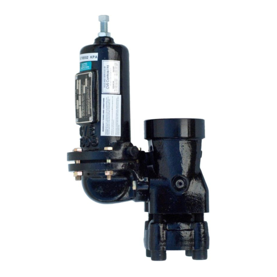
Figure 1: CVS Type 630HP Regulator
be as indicated by the flow direction arrow on
nameplate.
Note that in diagrams in this manual, regulator flow
direction is opposite relief valve flow direction.
Protect the regulator or relief valve against damage
from vehicles and other external sources. The
temperature capability of the 630 HP Series
regulator and relief valves with standard construction
materials is –20 to +150F, optional construction -20
to 300
o
F.
E-Mail: info@cvs-controls.com
Calgary Sales Office
3516 114 Avenue SE
Calgary, Alberta, Canada T2Z 3V6
Office: (403) 250-1416
Fax: (403) 291-9487
1
Advertisement
Table of Contents

Related Manuals for CVS Controls 630


Summary of Contents for CVS Controls 630
- Page 1 CVS instructions and all applicable federal, provincial, state and local codes, laws, rules, and regulations. The CVS 630 HP Series consists of a high pressure reducing regulator, and Type CVS 630R relief valve. These regulators and relief valves are furnished in...
-
Page 2: Overpressure Protection
Table 1: Maximum Inlet Pressures and Pressure Drops for CVS Type 630 HP Regulators 1/8” & 3/16” 1/4” Port 3/8” Port 1/2”... - Page 3 For outlet pressure settings to 350 psig only. For pressure settings over 350 psig, outlet pressure is limited by max. emergency outlet pressure of 550 psig. Leakage or bursting of pressure-containing parts may occur if outlet pressure exceeds these values. Table 3: Loading Pressure and Outlet Pressure Limits for Spring-Loaded CVS Type 630 HP Regulators...
-
Page 4: Taking Out Of Service
Some pressure ratings are dependent upon the pressure to loading regulator. actual outlet pressure settings being used. For example, with a Type 630 HP regulator, outlet Cautiously vent all pressure from the regulator or pressure must not exceed the setting by more than... -
Page 5: Maintenance
(Key 12) and disassemble the 2. Remove seat ring (Key 4) and gaskets (Key 5). diaphragm assembly. 3. To remove Type 630 HP valve disc (Key 3) OR 7. Install new diaphragm. Note that low-pressure Type 630R valve seat O-ring (Key 32), first constructions use a diaphragm plate (Key 16) disconnect remote vent pipe (if one is used). -
Page 6: Nameplate Information
Nameplate Information 9. To ensure proper slack in the diaphragm: When corresponding with your CVS Controls 9.1 For constructions using a spring, tighten the representative about this device, state the model spring case cap screws finger tight only. number, pressure range and all other pertinent Compress the spring slightly with the information found on the nameplate (Key 29). -
Page 7: Parts Reference
Machine Screw (CVS Type 630R Only) O-Ring Head Gasket (Pressure Loaded Only) Gasket (Pressure Loaded Only) Gasket (Pressure Loaded Only) Pipe Nipple (Pressure Loaded Only) Street Elbow Bleed Orifice Assembly (Pressure Loaded Only) Figure 2: Pressure-Loaded CVS Type 630 Regulator High Pressure Connection... - Page 8 Figure 3: Spring-Loaded CVS Type 630R Relief Valve Low Pressure Connection Figure 4: Pressure-Loaded CVS Type 630R Relief Valve Low Pressure Connection...
-
Page 9: Parts List
CVS Type 630 HP Regulators and Relief Valves Parts List Description Part # 1” Steel w/ brass pitot tube Body CVS2N6990000A2 1” Steel w/ SST pitot tube CVS2N6990X0012 2” Steel w/ SST pitot tube CVS2N699122012 Brass CVS0W018614022 Valve Carrier CVS0W018635032... - Page 10 CVS Type 630 HP Regulators and Relief Valves Parts List cont’d Description Part # Spring See Following Table 630 Pressure Loaded None Required Pressure Range to 275 CVS0W019344022 Upper Spring Seat, Zinc 630 and 630R, and 630R Pressure Range over...
- Page 11 Cadmium High-Pressure 75 to 175 CVS0Y0664000A2 Green Stripe 150 to 250 CVS1J146927142 Blue Stripe 10 to 20 or Low-Pressure CVS0W019227022 Red Stripe 20 to 50 Pressure-Loaded Type 630 R 50 to 100 or High-Pressure CVS0W019227022 Red Stripe 100 to 225...
-
Page 12: Dimensional Data
Dimensional Data:... - Page 13 Air – 0.775; Nitrogen – 0.789; Propane – 0.628; Butane; 0.548. Table 1: CVS Type 630 Regulator Capacity – SCFH of 0.6 Specific Gravity Gas; based on 20% Droop OUTLET...
- Page 14 Table 1(continued): CVS Type 630 Regulator Capacity – SCFH of 0.6 Specific Gravity Gas; based on 20% Droop Outlet Inlet Outlet 1 Inch Body 2 Inch Body Pressure Pressure Pressure Port Diameter - Inches Port Diameter - Inches Range PSIG...
- Page 15 Table 1(continued): CVS Type 630 Regulator Capacity – SCFH of 0.6 Specific Gravity Gas; based on 20% Droop OUTLET INLET OUTLET 1 Inch Body 2 Inch Body PRESSURE PRESSSURE PRESSURE Port Diameter - Inches Port Diameter - Inches RANGE PSIG...
- Page 16 Table 1(continued): CVS Type 630 Regulator Capacity – SCFH of 0.6 Specific Gravity Gas; based on 20% Droop OUTLET INLET OUTLET 1 Inch Body 2 Inch Body PRESSURE PRESSURE PRESSURE Port Diameter - Inches Port Diameter - Inches RANGE PSIG...
- Page 17 Table 1(continued): CVS Type 630 Regulator Capacity – SCFH of 0.6 Specific Gravity Gas; based on 20% Droop OUTLET INLET OUTLET 1 Inch Body 2 Inch Body PRESSURE PRESSURE PRESSURE Port Diameter - Inches Port Diameter - Inches RANGE PSIG...
- Page 18 NOTES:...
- Page 19 NOTES: CVS Controls Ltd. strives for the highest levels of quality and accuracy. The information included in this publication is presented for informational purposes only. CVS Controls Ltd. reserves the right to modify or change, and improve design, process, and specifications without written notice. Under no circumstance is the information contained to be interpreted to be a guarantee/warranty with regard to our products or services, applicability or use.
- Page 20 Head Office Calgary Sales Office 3900 101 Street 3516 114 Avenue SE Edmonton, Alberta Calgary, Alberta T6E 0A5 T2Z 3V6 Canada Canada Office: (780) 437-3055 Office: (403) 250-1416 Fax: (780) 436 5461 Fax: (403) 291-9487 Website: www.cvs-controls.com Email: info@cvs-controls.com June 2021...
Need help?
Do you have a question about the 630 and is the answer not in the manual?
Questions and answers