Table of Contents
Advertisement
Quick Links
Operator's manual, EN
Dear customer,
Thank you for choosing a Husqvarna quality product. We hope that you will
genuinely enjoy it.
Please note that the enclosed manual contains Wacker Neuson references.
The Husqvarna Group is vouching for the quality of this product.
If you have any questions, please do not hesitate to contact our local sales or
service point, or visit www.husqvarnacp.com.
Husqvarna AB
SE-561 82 Huskvarna, Sweden
CRT 48-35L-PS
CRT 48-37V-PS
CRT 48-57K-PS
Huskvarna, 2019-12-01
1142225-26
Advertisement
Chapters
Table of Contents

Related Manuals for Husqvarna CRT 48-35L-PS


Summary of Contents for Husqvarna CRT 48-35L-PS
- Page 1 Huskvarna, 2019-12-01 Operator’s manual, EN Dear customer, Thank you for choosing a Husqvarna quality product. We hope that you will genuinely enjoy it. Please note that the enclosed manual contains Wacker Neuson references. The Husqvarna Group is vouching for the quality of this product.
- Page 2 Operator’s Manual Ride-On Trowel CRT48-35L-PS CRT48-37V-PS CRT48-57K-PS Type CRT48-35L-PS, CRT48-37V-PS, CRT48-57K-PS Document 5000184417 Date 0719 Revision Language 5 0 0 0 1 8 4 4 1 7...
-
Page 3: California Proposition 65 Warning
CALIFORNIA Proposition 65 Warning CALIFORNIA Proposition 65 Warning WARNING The engine exhaust from this product contains chemicals known to the State of California to cause cancer, birth defects, or other reproductive harm. WARNING Diesel engine exhaust and some of its constituents are known to the State of California to cause cancer, birth defects, and other reproductive harm. - Page 4 CALIFORNIA Proposition 65 Warning Notes wc_tx004643en.fm...
-
Page 5: Foreword
CRT48-PS Foreword Foreword SAVE THESE INSTRUCTIONS—This manual contains important instructions for the machine models below. These instructions have been written expressly by Wacker Neuson Production Americas LLC and must be followed during installation, operation, and maintenance of the machines. Machine Item Number CRT48-35L-PS 5000620704, 5000620900... - Page 6 Foreword CRT48-PS ■ This manual provides information and procedures to safely operate and Expectations maintain the above Wacker Neuson model(s). For your own safety and to information in reduce the risk of injury, carefully read, understand, and observe all instructions this manual described in this manual.
-
Page 7: Ec Declaration Of Conformity
EC Declaration of Conformity We, Husqvarna AB, SE 561 82 Huskvarna, SWEDEN, Tel. +46 36 146500 declare on our sole responsibility that the product: Description Concrete Smoothing Machine, Trowel Brand HUSQVARNA Type / Model CRT 48-57K-PS Identification Serial numbers dating from 2019 and onwards... -
Page 9: Table Of Contents
CRT48-PS Table of Contents CALIFORNIA Proposition 65 Warning Foreword EC Declaration of Conformity Safety Information Signal Words Used in this Manual ............. 13 Machine Description and Intended Use ..........14 Safety Guidelines for Operating the Machine ........15 Service Safety ..................17 Operator Safety while Using Internal Combustion Engines .... - Page 10 Table of Contents CRT48-PS 4.13 Adjusting the Pitch ................50 4.14 Steering Controller Fault Codes ............51 4.15 Using the Work Lights .................53 4.16 Using the Retardant Spray System .............54 General Maintenance Maintaining the Emission Control System ...........55 Periodic Maintenance Schedule ............56 Maintaining the Gearboxes ..............57 Adjusting the Blade Arms ..............59 Lubricate the Trowel Arms ..............61...
- Page 11 Systems .................... 106 13 AEM Safety Manual 14 Schematics 14.1 Electrical Schematic: CRT 48-35L-PS ..........130 14.2 Electrical Schematic Components: CRT 48-35L-PS ......131 14.3 Electrical Schematic: CRT 48-37V-PS ..........132 14.4 Electrical Schematic Components: CRT 48-37V-PS ......133 14.5 Fuse/Relay Box Layout ..............
- Page 12 Table of Contents CRT48-PS wc_bo5000184417_14TOC.fm...
-
Page 13: Safety Information
CRT48-PS Safety Information Safety Information Signal Words Used in this Manual This manual contains DANGER, WARNING, CAUTION, NOTICE, and NOTE signal words which must be followed to reduce the possibility of personal injury, damage to the equipment, or improper service. This is the safety alert symbol. -
Page 14: Machine Description And Intended Use
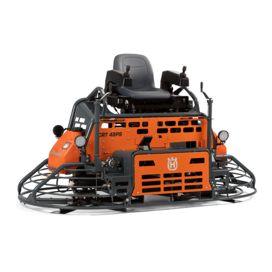
Safety Information CRT48-PS Machine Description and Intended Use This machine is a ride-on concrete finishing trowel. The Wacker Neuson Ride-On Trowel consists of a frame onto which are mounted a gasoline or diesel engine, a fuel tank, a water tank, two gearboxes joined by a drive shaft, and an operator’s platform with controls and a seat. -
Page 15: Safety Guidelines For Operating The Machine
CRT48-PS Safety Information Safety Guidelines for Operating the Machine Operator Before operating the machine: training ■ Read and understand the operating instructions contained in all manuals delivered with the machine. ■ Familiarize yourself with the location and proper use of all controls and safety devices. - Page 16 Safety Information CRT48-PS ■ Do not operate the machine if any safety devices or guards are missing or inoperative. ■ Do not modify or defeat the safety devices. ■ Only use accessories or attachments that are approved by Wacker Neuson. Safe When operating this machine: operating...
-
Page 17: Service Safety
CRT48-PS Safety Information Service Safety Service Before servicing or maintaining the machine: training ■ Read and understand the instructions contained in all manuals delivered with the machine. ■ Familiarize yourself with the location and proper use of all controls and protective devices. - Page 18 Safety Information CRT48-PS ■ Never use gasoline or other types of fuels or flammable solvents to clean the machine. Fumes from fuels and solvents can become explosive. Personal Wear the following Personal Protective Equipment (PPE) while servicing or protective maintaining this machine: equipment ■...
-
Page 19: Operator Safety While Using Internal Combustion Engines
CRT48-PS Safety Information Operator Safety while Using Internal Combustion Engines WARNING Internal combustion engines present special hazards during operation and fueling. Failure to follow the warnings and safety standards could result in severe injury or death. ► Read and follow the warning instructions in the engine owner’s manual and the safety guidelines below. -
Page 20: Safety Guidelines For Lifting The Machine
Safety Information CRT48-PS Safety Guidelines for Lifting the Machine When lifting the machine: ■ Make sure slings, chains, hooks, ramps, jacks, forklifts, cranes, hoists, and any other type of lifting device used is attached securely and has enough weight- bearing capacity to lift or hold the machine safely. See the Technical Data chapter for machine weight. - Page 21 CRT48-PS Safety Information Notes wc_si000342gb_FM10.fm...
-
Page 22: Labels
Labels CRT48-PS Labels Label Locations wc_gr011891 wc_si000435gb_FM10.fm... -
Page 23: Label Meanings
CRT48-PS Labels Label Meanings DANGER Asphyxiation hazard ■ Engines emit carbon monoxide. ■ Do not run the machine indoors or in an enclosed area unless adequate ventilation, through such items as exhaust fans or hoses, is provided. ■ Read the Operator’s Manual. ■... - Page 24 Labels CRT48-PS Read and understand the supplied Operator’s WARNING WARNING Manual before operating this machine. Failure READ AND UNDERSTAND THE SUPPLIED OPERATOR'S MANUAL BEFORE OPERATING THIS MACHINE. READ AND UNDERSTAND THE SUPPLIED OPERATOR'S MANUAL BEFORE OPERATING THIS MACHINE. FAILURE TO DO SO INCREASES THE RISK OF INJURY TO YOURSELF OR OTHERS. FAILURE TO DO SO INCREASES THE RISK OF INJURY TO YOURSELF OR OTHERS.
- Page 25 CRT48-PS Labels WARNING Pressurized contents. Do not open when hot! WARNING WARNING ADVERTENCIA ADVERTENCIA AVERTISSEMENT AVERTISSEMENT 110164 110164 178711 WARNING Hand injury if caught in moving belt. Always replace beltguard. NOTICE Lifting point XXX kg XXX kg (XXXX LBS) (XXXX LBS) 5200014673 5200014673 Tie-down point...
- Page 26 Labels CRT48-PS Operator’s Manual must be stored on OPERATOR'S MANUAL MUST BE STORED ON MACHINE. OPERATOR'S MANUAL MUST BE STORED ON MACHINE. machine. Replacement Operator’s Manual REPLACEMENT OPERATOR'S MANUAL CAN BE ORDERED REPLACEMENT OPERATOR'S MANUAL CAN BE ORDERED can be ordered through your local Wacker THROUGH YOUR LOCAL WACKER DISTRIBUTOR.
- Page 27 CRT48-PS Labels CAUTION Engine oil pressure is low! Stop the engine and check the oil level. 164910 164910 CAUTION Low voltage! Stop the engine and check the charging system. 164471 164471 CAUTION Coolant temperature is too high. Stop the engine and check the coolant level. 164909 164909 CAUTION...
- Page 28 Labels CRT48-PS WARNING Explosion hazard. WARNING WARNING Do not use evaporative starting fluids such ADVERTENCIA ADVERTENCIA ■ as ether on this engine. AVERTISSEMENT AVERTISSEMENT 5200005890 5200005890 The engine is equipped with a cold starting ■ aid. Using evaporative starting fluids can cause an explosion which can cause engine damage, personal injury, or death.
- Page 29 CRT48-PS Labels Hydraulic oil reservoir fill 111760 111760 Dynamic Steering Stabilization Location of steering mode switch 182270 182270 Steering mode switch position 181230 181230 Emission Control Information This equipment meets U.S. EPA EVAP standards. (if equipped) wc_si000435gb_FM10.fm...
- Page 30 Labels CRT48-PS Read Operator’s Manual. Steering system components are under load. See topic Steering or a trained service CAUTION CAUTION ATENCION ATENCION technician for adjustments. STEERING ASSIST SYSTEM UNDER STEERING ASSIST SYSTEM UNDER LA DIRECCION SERVO ASISTIDA LA DIRECCION SERVO ASISTIDA LOAD.
-
Page 31: Lifting And Transporting
CRT48-PS Lifting and Transporting Lifting and Transporting Lifting the Machine Background The machine is equipped with fork lift pockets (a) on the front and back, and two lifting tubes (b). wc_gr011877 Requirements ■ Lifting equipment (crane, hoist, or fork truck) capable of supporting the machine's weight ■... -
Page 32: Preparing The Machine For Transport On A Truck Or Trailer
Lifting and Transporting CRT48-PS Preparing the Machine for Transport on a Truck or Trailer Requirements ■ Machine stopped ■ Flatbed truck or trailer capable of supporting the machine’s weight ■ Chains, hooks, or straps capable of supporting the machine’s weight WARNING Crushing hazard. - Page 33 CRT48-PS Lifting and Transporting Note: Graphic is representative only. Your machine may vary. wc_gr011880 wc_tx001199gb_FM10.fm...
- Page 34 Lifting and Transporting CRT48-PS Notes wc_tx001199gb_FM10.fm...
-
Page 35: Operation
CRT48-PS Operation Operation Preparing the Machine for First Use 1. Make sure all loose packaging materials have been removed from the machine. 2. Check the machine and its components for damage. If there is visible damage, do not operate the machine. Contact your Wacker Neuson dealer immediately for assistance. -
Page 36: Machine Components
Operation CRT48-PS Machine Components wc_gr011905 wc_tx001200gb_FM10.fm... -
Page 37: Machine Components Descriptions
CRT48-PS Operation Machine Components Descriptions Ref. Description Ref. Description Right pitch control Work light switch Fuel tank Glow plug indicator light (if equipped) Joysticks Engine keyswitch Operator’s seat with “operator Hour meter presence” switch Left pitch control Water spray control Rear work light (one each side) Oil pressure indicator light Water tank... -
Page 38: Refueling The Machine
Operation CRT48-PS Refueling the Machine Requirements ■ Machine shut down ■ Engine cool ■ Machine/fuel tank level with the ground ■ Fresh, clean fuel supply Procedure Perform the procedure below to refuel the machine. WARNING Fire and burn hazard. Fuel and its vapors are extremely flammable. ►... -
Page 39: Break-In Period
CRT48-PS Operation Break-In Period Overview This machine requires a break-in period for the engine and the gearbox. Gearbox To break in the gearboxes, run the engine at 50% of full throttle for the first 2–4 break-in hours. This will prevent premature wear and extend gear life. period NOTICE: Running the engine at full throttle during the break-in period could result in premature gear failure. -
Page 40: Starting, Steering, Operating, And Stopping The Machine (Kohler)
Operation CRT48-PS Starting, Steering, Operating, and Stopping the Machine (Kohler) Requirements ■ Machine is in serviceable condition and has been properly maintained ■ There is fuel in the tank CAUTION Personal injury hazard. Operating the trowel with the armrests in the transport position can lead to personal injury. - Page 41 CRT48-PS Operation Steering The joysticks (c) control the travel direction and rotation of the machine. wc_gr011857 Hand motions Refer to the illustration for the necessary joystick motions to move the trowel in the desired direction. 1 — forward 2 — reverse 3 —...
- Page 42 Operation CRT48-PS Operating the Follow the guidelines below to use your Ride-On Trowel to its fullest capacity. machine ■ Operate the machine in the direction that the operator is facing. This will finish the widest possible area, while giving the operator an excellent view of the slab surface to be troweled.
-
Page 43: Starting, Steering, Operating, And Stopping The Machine (Vanguard)
CRT48-PS Operation Starting, Steering, Operating, and Stopping the Machine (Vanguard) Requirements ■ Machine is in serviceable condition and has been properly maintained ■ There is fuel in the tank CAUTION Personal injury hazard. Operating the trowel with the armrests in the transport position can lead to personal injury. - Page 44 Operation CRT48-PS Continued from the previous page. Steering The joysticks (b) control the travel direction and rotation of the machine. wc_gr012802 Hand motions Refer to the illustration for the necessary joystick motions to move the trowel in the desired direction. 1 —...
- Page 45 CRT48-PS Operation Operating the Follow the guidelines below to use your Ride-On Trowel to its fullest capacity. machine ■ Operate the machine in the direction that the operator is facing. This will finish the widest possible area, while giving the operator an excellent view of the slab surface to be troweled.
-
Page 46: Starting, Steering, Operating, And Stopping The Machine (Kubota)
Operation CRT48-PS 4.10 Starting, Steering, Operating, and Stopping the Machine (Kubota) Requirements ■ Machine is in serviceable condition and has been properly maintained ■ There is fuel in the tank CAUTION Personal injury hazard. Operating the trowel with the armrests in the transport position can lead to personal injury. - Page 47 CRT48-PS Operation Steering The joysticks (b) control the travel direction and rotation of the machine. wc_gr012802 Hand motions Refer to the illustration for the necessary joystick motions to move the trowel in the desired direction. 1 — forward 2 — reverse 3 —...
-
Page 48: Emergency Shutdown Procedure
Operation CRT48-PS Operating the Follow the guidelines below to use your Ride-On Trowel to its fullest capacity. machine ■ Operate the machine in the direction that the operator is facing. This will finish the widest possible area, while giving the operator an excellent view of the slab surface to be troweled. -
Page 49: Using The Steering Mode Switch
CRT48-PS Operation 4.12 Using the Steering Mode Switch Overview The steering mode switch (a) allows the operator to adjust the response of the joysticks depending upon the intended machine movement or concrete surface condition. wc_gr011858 Switch positions Position Meaning Machine response Recommended use High Joysticks display standard... -
Page 50: Adjusting The Pitch
Operation CRT48-PS 4.13 Adjusting the Pitch Background Changing the pitch (angle) of the trowel blades enables the operator to finish concrete from the wet surface stage through the hard finishing stage (burnishing). 5-10 º 15º 20-25 º wc_gr011860 Changing Perform the procedure below to change or set the pitch angle of the trowel blades. pitch angle 1. -
Page 51: Steering Controller Fault Codes
CRT48-PS Operation 4.14 Steering Controller Fault Codes Background The steering system electronically converts the operator’s joystick movements into hydraulic force at the steering cylinders. An electronic controller located under the right hand machine lift point contains the control logic which runs the steering cartridge valves. - Page 52 Operation CRT48-PS Fault Codes Code Description Y-Axis Right joystick fault. Out of range. X-Axis Right joystick fault. Out of range. Y-Axis Left joystick fault. Out of range. Right rocker fault. Out of range. Left rocker fault. Out of range. R Right Coil disconnected, burnt out or overdriven. R Left Coil disconnected, burnt out or overdriven.
-
Page 53: Using The Work Lights
CRT48-PS Operation 4.15 Using the Work Lights Background The machine is equipped with four work lights. The work lights are controlled by a single rocker switch below the left joystick. The rocker switch (a) controls the front and rear work lights. wc_gr011861 wc_tx001200gb_FM10.fm... -
Page 54: Using The Retardant Spray System
Operation CRT48-PS 4.16 Using the Retardant Spray System Requirements ■ Water/retardant in water tank ■ Ambient temperature above freezing Background The retardant spray system is controlled by a switch located on the right joystick. Procedure Perform the procedure below to operate the retardant spray system. 1. -
Page 55: General Maintenance
CRT48-PS General Maintenance General Maintenance WARNING A poorly maintained machine can malfunction, causing injuries or permanent damage to the machine. ► Keep the machine in safe operating condition by performing periodic maintenance and making repairs as needed. Maintaining the Emission Control System For machines sold in North America: Normal maintenance, replacement, or repair of emission control devices and systems may be performed by any repair establishment or individual;... -
Page 56: Periodic Maintenance Schedule
General Maintenance CRT48-PS Periodic Maintenance Schedule The table below lists basic machine maintenance. Tasks designated with check marks may be performed by the operator. Tasks designated with square bullet points require special training and equipment. Every Every 20 Every 50 Daily hours... -
Page 57: Maintaining The Gearboxes
CRT48-PS General Maintenance Maintaining the Gearboxes ► Check the gearboxes for the correct oil level after every 20 hours of operation. When ► Change the gearbox oil every 300 hours. ► Clear clogs from, or replace, pressure relief valve (a) as needed to prevent oil leakage from gearbox shaft seals. - Page 58 General Maintenance CRT48-PS Changing Perform the procedure below to change the gearbox oil. gearbox oil 1. Place a container of sufficient capacity (approximately 3.8 L [1 gallon]) under each gearbox. 2. Remove the gearbox oil drain plug (c) and allow the oil to drain. It may be necessary to remove the gearbox oil fill plug(s) to facilitate draining.
-
Page 59: Adjusting The Blade Arms
CRT48-PS General Maintenance Adjusting the Blade Arms When Adjust the blade arms if the machine is wobbling during operation, after replacing an arm, or after disassembling the spider assembly. Requirements ■ Machine stopped ■ Lifting devices with enough weight-bearing capacity to lift the machine ■... - Page 60 General Maintenance CRT48-PS Continued from the previous page. 5. There is a small amount of play in the connection between the blade arm and the spider (lift plate). Gently wiggle each blade so that the lower end of the blade is at the lowest point of the play.
-
Page 61: Lubricate The Trowel Arms
CRT48-PS General Maintenance Lubricate the Trowel Arms Requirements ■ Machine stopped ■ Grease (Unirex N2) or equivalent Procedure Perform the procedure below to grease the trowel arms. 1. Set the trowel on a flat, level surface. 2. Disconnect the battery. 3. -
Page 62: Mounting Float Pans
General Maintenance CRT48-PS Mounting Float Pans Background Certain applications may require the use of float pans. Optional float pans are available from your Wacker Neuson dealer. The blade arms on the machine are designed to accommodate either a standard 48" lip-style float pan or an optional smaller 46"... - Page 63 CRT48-PS General Maintenance Continued from the previous page. 5. Lower the machine. WARNING Float pans can fall off a raised trowel, striking nearby personnel. ► Do not lift the trowel overhead after float pans have been mounted. Mounting a Perform the procedure below to mount a 46" float pan. 46"...
-
Page 64: Replacing The Drive Belt
General Maintenance CRT48-PS Replacing the Drive Belt ► Check the drive belt every 50 hours When ► Replace the drive belt if it is worn or damaged. Requirements ■ Machine stopped ■ Replacement drive belt (in necessary) Procedure Perform the procedure below to replace the drive belt. 1. - Page 65 CRT48-PS General Maintenance Reassembly Perform the procedure below to reassemble the belt drive. 1. Align the pillow bearing and shaft as straight as possible. Adjust pulley offset and center distance to values as shown. 2. Re-install the three bolts and torque to 14 ±1.4 Nm (10 ±1 ft.lbs.). 3.
-
Page 66: Installing Or Changing The Blades
General Maintenance CRT48-PS Installing or Changing the Blades Introduction There are two types of blades available for the trowel: ■ Combination blades can be used throughout the entire concrete working process, from floating to finishing stages. They are designed for rotation in one direction only. - Page 67 CRT48-PS General Maintenance Continued from the previous page. 2. Position and align the blades. ■ If installing combination blades (d), orient the blades as shown in the diagram and align the screw holes. This positions the raised edge of each blade correctly for the rotation of each rotor.
-
Page 68: Cleaning The Machine
General Maintenance CRT48-PS Cleaning the Machine When Clean the machine after each use. Background Regular cleaning is essential for keeping the trowel in serviceable condition. It is important to remove uncured concrete, dust and dirt from the trowel as soon as possible after work has been completed. -
Page 69: Storage
CRT48-PS General Maintenance 5.10 Storage Extended storage of equipment requires preventive maintenance. Performing these steps helps to preserve machine components and ensures the machine will be ready for future use. While not all of these steps necessarily apply to this machine, the basic procedures remain the same. -
Page 70: Machine Disposal / Decommissioning
General Maintenance CRT48-PS 5.11 Machine Disposal / Decommissioning Introduction This machine must be properly decommissioned at the end of its service life. Responsible disposal of recyclable components, such as plastic and metal, ensures that these materials can be reused—conserving landfill space and valuable natural resources. -
Page 71: Engine Maintenance: Kohler
Engine Maintenance: KOHLER Engine Maintenance: KOHLER The information in this chapter comes from copyrighted Kohler material. The viscosity of the engine oil is an important factor when determining the correct engine oil to use in your machine. Use an engine oil of appropriate viscosity based on the expected outside air temperature. - Page 72 Engine Maintenance: KOHLER wc_tx003649gb_FM10.fm...
- Page 73 Engine Maintenance: KOHLER The engine maintenance schedule(s) in this chapter are reproduced from the engine owner’s manual. For additional information, see the engine owner’s manual. wc_tx003649gb_FM10.fm...
- Page 74 Engine Maintenance: KOHLER wc_tx003649gb_FM10.fm...
- Page 75 Engine Maintenance: KOHLER wc_tx003649gb_FM10.fm...
-
Page 76: Engine Maintenance: Vanguard
Engine Maintenance: Vanguard Engine Maintenance: Vanguard The information in this chapter comes from copyrighted Vanguard material. The viscosity of the engine oil is an important factor when determining the correct engine oil to use in your machine. Use an engine oil of appropriate viscosity based on the expected outside air temperature. - Page 77 Engine Maintenance: Vanguard The engine maintenance schedule(s) in this chapter are reproduced from the engine owner’s manual. For additional information, see the engine owner’s manual. Maintenance Chart First 5 Hours Change oil Every 8 Hours or Daily Check engine oil level Clean area around muffler and controls Every 100 Hours or Annually Clean or change air filter *...
-
Page 78: Engine Maintenance: Kubota
Engine Maintenance: Kubota Engine Maintenance: Kubota The information in this chapter comes from copyrighted Kubota material. The viscosity of the engine oil is an important factor when determining the correct engine oil to use in your machine. Use an engine oil of appropriate viscosity based on the expected outside air temperature. - Page 79 Engine Maintenance: Kubota The engine maintenance schedule(s) in this chapter are reproduced from the engine owner’s manual. For additional information, see the engine owner’s manual. SERVICE INTERVALS Non-warranty maintenance, repair, or replacement of the emission control devices and systems should be performed by a qualified repair establishment or individual which has the experience and equipment to perform such work.
- Page 80 Engine Maintenance: Kubota Interval Every Every Each Items Remarks 1000 2000 Yearly hours hours years Each part Check / Clean Check / Replenish Engine oil Change Oil filter cartridge Change Clean Spark plug Adjust Change Check Air cleaner element Clean Change Intake pipe / Change...
- Page 81 Engine Maintenance: Kubota Interval Every Every Every Every Items Remarks 8 hours 50 hours (daily) (weekly) hours hours Breather tube Change PCV valve Check Check Hot water line LPG vaporizer Change Hot water line regulator Check inner parts*2 LPG Lock off valve Check Check Battery...
- Page 82 Engine Maintenance: Kubota Interval Every Every Each Items Remarks 1000 2000 Yearly hours hours years Breather tube Change PCV valve Check Check Hot water line LPG vaporizer Change Hot water line regulator Check inner parts*2 LPG Lock off valve Check Check Battery Change...
-
Page 83: Troubleshooting
CRT48-PS Troubleshooting Troubleshooting Problem Cause Remedy Engine doesn’t start No fuel in tank Add fuel. Battery connections loose Check and clean battery or corroded connections. Battery charge low Charge or replace battery. Defective starter Replace starter. Engine is hard to start. No fuel in tank Add fuel. -
Page 84: Setting Up The Diagnostic Tool
Troubleshooting CRT48-PS Setting Up the Diagnostic Tool Background A diagnostic tool is available to aid in diagnosing component malfunctions. The diagnostic tool consists of an application program provided by Danfoss, a series of diagnostic files depending on the machine model, and a cable assembly to connect the machine to a computer. - Page 85 CRT48-PS Troubleshooting Download the The trowel diagnostic files are available as attachments to the PDF version of the diagnostic file Operator’s Manual and/or the Repair Manual for your machine. See the Wacker Neuson Web site: www.wackerneuson.com. wc_gr012306 wc_tx001203gb_FM10.fm...
- Page 86 Troubleshooting CRT48-PS Connections Perform the procedure below to connect the computer to the machine. 1. Plug the USB cable into the computer to be used for diagnostics. The green “PWR” LED will illuminate when connected properly. wc_gr012305 2. Locate the trowel’s 3-pin connector (x). CRT 60 CRT 48 wc_gr012304...
- Page 87 CRT48-PS Troubleshooting Starting the 1. Turn the key to the ON position, or start the engine. Program 2. Start the PLUS+1 GUIDE Service Tool program. ► If prompted, select gateway “CG 150”. ► If prompted, select channel CG150 #0 (Channel 0). 3.
- Page 88 Troubleshooting CRT48-PS Continued from the previous page. 4. Open the appropriate diagnostic file for the machine you are working on. wc_gr012308 5. After the file loads, click “Main”. wc_gr012309 This procedure continues on the next page. wc_tx001203gb_FM10.fm...
- Page 89 CRT48-PS Troubleshooting Continued from the previous page. 6. The diagnostic screen appears. The diagnostic screen shows the voltage and amperage values that are being sent to the controller via the joysticks and via the foot pedal. It also shows the amperage values being sent from the controller to the valves on the manifold.
- Page 90 Troubleshooting CRT48-PS Continued from the previous page. CRT 60 CRT 60 diagnostic screen is shown below. Readout explanations SEAT SWITCH CRUISE RIGHT JOYSTICK FWD/REV LEFT JOYSTICK FWD/REV NOT USED ENGINE SPEED RIGHT JOYSTICK LEFT/RIGHT CRT 60 FOOT PEDAL wc_gr012312 Seat switch Identifier Meaning 0,4 - CP_SEAT_SW...
- Page 91 CRT48-PS Troubleshooting CP_R_YAXIS_mV Voltage (mV) from right joystick to controller: 500 = REV, 2500 = Neutral, 4500 = FWD CP_FLT_LEFT_Y Left joystick fault: red = no fault; green = fault CP_FLT_R_FWD_COIL FWD valve (1B) fault: red = no fault; green = fault CP_FLT_R_REV_COIL REV valve (1A) fault: red = no fault;...
- Page 92 Troubleshooting CRT48-PS Continued from the previous page. CRT 48 CRT 48 diagnostic screen is shown below. Readout explanations CRT 48 wc_gr012311 Spray system Identifier Meaning CP_FLT_L_ROCKER Left rocker switch fault: red = no fault; green = fault CP_LEFT_ROCKER CP_WATER_PUMP Red = OFF; green = ON CP_FLT_R_ROCKER Right rocker switch fault: red = no fault;...
- Page 93 CRT48-PS Troubleshooting Right joystick LEFT/RIGHT CP_R_XAXIS_mV Voltage (mV) from right joystick to controller: 500 = REV, 2500 = Neutral, 4500 = FWD CP_FLT_RIGHT_X Right joystick fault: red = no fault; green = fault CP_R_LEFT Amperage from controller to valve (3B) 16000 = 1.6A CP_R_RIGHT Amperage from controller to valve (3A) 16000 = 1.6A CP_FLT_R_LEFT_COIL...
-
Page 94: 10 Technical Data
Technical Data CRT48-PS 10 Technical Data 10.1 Engine Model CRT48-35L-PS CRT 48-37V-PS CRT 48-57K-PS Engine make Kohler Vanguard Kubota Engine model KDW1404 A/C V-Twin WG1605-G Maximum rated power @ kW (hp) 26 (34.9) @ 3,600 27.6 (37) @ 3,600 42.5 (57) @ 3600 rated speed Displacement cm³... -
Page 95: Trowel
CRT48-PS Technical Data 10.2 Trowel Machine CRT48-35L-PS CRT 48-37V-PS CRT 48-57K-PS Operating weight kg (lb) 643 (1420) 600 (1324) 660 (1456) Dimensions (L x W x H) 2566 x 1295 x 1473 (in.) (101 x 51 x 58) Rotor speed (range) 25–150 25–165 25–150... -
Page 96: Sound Measurements
The required sound specifications, per Annex VIII, European Directive 2006/42/EC of the EC Machine Regulations, are: Sound Pressure at Operator’s Guaranteed Sound Power Machine Location dB(A) dB(A) CRT 48-35L-PS 91.1 110.2 CRT 48-37V-PS 94.8 110.3 CRT 48-57K-PS 94.3 111.7... -
Page 97: Dimensions
CRT48-PS Technical Data 10.5 Dimensions mm (in.) 1473 (58) 2566 (101) 1295 (51) wc_gr011881 wc_td000350gb_FM10.fm... - Page 98 Technical Data CRT48-PS Notes wc_td000350gb_FM10.fm...
-
Page 99: Emission Control Systems Information And Warranty-Diesel
Emission Control Systems Information and Warranty—Diesel 11 Emission Control Systems Information and Warranty Diesel — The Emission Control Warranty and associated information is valid only for the U.S.A., its territories, and Canada. 11.1 Emission Control System Background Information Introduction Wacker Neuson engines/equipment must conform with applicable Environmental Protection Agency (EPA) and California Air Resource Board (CARB) emissions regulations. -
Page 100: Limited Defect Warranty For Wacker Neuson Emission Control
Emission Control Systems Information and Warranty—Diesel 11.2 Limited Defect Warranty for Wacker Neuson Emission Control Systems The Emission Control Warranty is valid only for the U.S.A., its territories, and Canada. Wacker Neuson Sales Americas, LLC, N92 W15000 Anthony Avenue, Menomonee Falls, WI 53051, (hereinafter “Wacker Neuson”) warrants to the initial retail purchaser and each subsequent owner, that this engine/equipment, including all parts of its emission control system, have been designed, built, and equipped to conform at the time of initial sale to all applicable evaporative emission regulations... - Page 101 Emission Control Systems Information and Warranty—Diesel ■ Incidental or consequential damages such as loss of time or the use of the engine/equipment, or any commercial loss due to the failure of the engine/ equipment. ■ Diagnosis and inspection charges that do not result in warranty-eligible service being performed.
- Page 102 Emission Control Systems Information and Warranty—Diesel How to Make a Claim In the event that any emission-related part is found to be defective during the warranty period, you shall notify Wacker Neuson Product Support Department (1-800-770-0957, or technical.support@wackerneuson.com, or wackerneuson.com), and you will be advised of the appropriate dealer/service center where warranty repair can be performed.
- Page 103 Emissions Control Systems Information and Warranty 11 Emissions Control Systems Information and Warranty System Covered Components Air filter system and associated plumbing Air filter (Before engine intake) Exhaust system Exhaust system connected after the exhaust manifold wc_tx004132gb_FM10.fm...
- Page 104 Emissions Control Systems Information and Warranty 11 Emissions Control Systems Information and Warranty Limited Defect Warranty Period for Wacker Neuson Emission Control Systems The warranty period for this engine/equipment begins on the date of sale to the initial purchaser and continues for a period of 5 years or 3000 hours of operation (whichever comes first).
-
Page 105: Emission Control Systems Information And Warranty-Gasoline
Emission Control Systems Information and Warranty—Gasoline 12 Emission Control Systems Information and Warranty Gasoline — The Emission Control Warranty and associated information is valid only for the U.S.A., its territories, and Canada. 12.1 Emission Control System Background Information Introduction Wacker Neuson spark-ignited engines/equipment must conform with applicable Environmental Protection Agency (EPA) emissions regulations. -
Page 106: Limited Defect Warranty For Wacker Neuson Emission Control
Emission Control Systems Information and Warranty—Gasoline Tampering and Altering Tampering with or altering the emission control system may increase emissions beyond the legal limit. If evidence of tampering is found, Wacker Neuson may deny a warranty claim. Among those acts that constitute tampering are: ■... - Page 107 Emission Control Systems Information and Warranty—Gasoline ■ Any systems or parts which are affected or damaged by owner abuse, tampering, neglect, improper maintenance, misuse, improper fueling, improper storage, accident and/or collision; the incorporation of, or any use of, add-on or modified parts, or unsuitable attachments, or the alteration of any part.
- Page 108 Emission Control Systems Information and Warranty—Gasoline For owners located more than 100 miles from an authorized dealer/service center (excluding the states with high-altitude areas as identified in 40 CFR Part 1068, Appendix III), Wacker Neuson will pay for pre-approved shipping costs to and from an authorized Wacker Neuson dealer/service center.
- Page 109 Emissions Control Systems Information and Warranty 12 Emissions Control Systems Information and Warranty CRT48-37V System Covered Components Evaporative control system Fuel tank Fuel cap Fuel line Fuel vent fitting See the supplied engine owner’s manual for the applicable exhaust emission warranty statement.
- Page 110 Emissions Control Systems Information and Warranty 12 Emissions Control Systems Information and Warranty Limited Defect Warranty Period for Wacker Neuson Emission Control Systems The warranty period for this engine/equipment begins on the date of sale to the initial purchaser and continues for a period of 3 years or 2500 hours of operation (whichever comes first).
-
Page 111: Aem Safety Manual
CONCRETE POWER TROWEL Table of Contents Acknowledgment ..............2 Foreword .................3 Safety Alerts ................4 A Word to the User/Operator ..........5 Follow a Safety Program............6 Prepare for Safe Operation ..........10 Start Safely ................17 Operate Safely ..............19 Shut Down Safely ..............21 Perform Maintenance Safely ..........22 Final Word to the User ............35 Acknowledgment We wish to thank the members of the Association of Equipment Manufacturers for their invaluable... -
Page 112: Foreword
Foreword This safety manual is intended to point out some of the basic safety situations that may be encountered during the normal operation and maintenance of your trowel Read and understand manuals before and to instruct you in safety practices for dealing with operating these conditions. -
Page 113: A Word To The User/Operator
A Word to the User/Operator It is YOUR responsibility to read and understand this Remember that YOU are the key to safety. Good safety manual and the manufacturer’s manual(s) before safety practices not only protect you but also protect operating this equipment. This safety manual takes you the people around you. - Page 114 Follow a Safety Program Be Careful! Human error is the result of many factors: carelessness, fatigue, sensory overload, preoccupation, unfamiliarity with the machine or attachments, or drugs and alcohol, to name a few. You can avoid death or serious injury caused by these and other unsafe work practices.
-
Page 115: Prepare For Safe Operation
Follow a Safety Program • Never allow children to play near, ride on or • Know the meaning of all identification symbols on the operate the equipment. controls and gauges • Keep bystanders away from the machine during • Know the location and type of emergency operation. - Page 116 Prepare for Safe Operation Check and Use All Check the Machine Available Safety Devices Before beginning your work day, inspect the machine and have all systems in good operational condition. To protect you and others around you, your machine may be equipped with the safety equipment listed •...
- Page 117 Prepare for Safe Operation Check the Cooling System Use Caution When Fueling When checking the cooling system, make sure the WARNING! Avoid injury from fire or explosion. engine is turned off and is cool. Remove the key to Never fill the fuel tank with the engine running, while prevent fans from unexpectedly starting.
- Page 118 Prepare for Safe Operation Avoid Crystalline Silica (quartz) Dust 3. Know the work operations where exposure to crystalline silica may occur. WARNING! Avoid exposure to dust containing 4. Participate in air monitoring or training programs crystalline silica particles. This dust can cause offered by the employer.
-
Page 119: Start Safely
Start Safely Warn Personnel Before Starting Starting the Engine Before starting, walk completely around the machine. WARNING! Never attempt to start the engine by Make sure no one is on it or close to it. Let others shorting across starter terminals. Serious injury or know you are starting up and don’t start until everyone death may result. -
Page 120: Operate Safely
Operate Safely Walk-Behind Trowels • If control of the trowel is lost, stay clear and do not attempt to regain control until the trowel has stopped • Ensure that the operator is familiar with the trowel moving. Depending on the engine speed, the trowel and is trained on its operation. -
Page 121: Shut Down Safely
Shut Down Safely Storage Always store equipment properly when it is not being used. Equipment should be stored in a clean, dry location out of reach of children. WARNING! Avoid death or serious injury. Never leave a machine unattended with the engine running. Safe Shutdown Shut engine off, remove key... - Page 122 Perform Maintenance Safely WARNING! Avoid death or serious injury from entanglement. Do not wear loose clothing or accessories. Stay away from all rotating components when the engine is running. Contact, wrapping or entanglement with rotating or moving parts could result in Avoid rotating parts death or serious injury.
- Page 123 Perform Maintenance Safely Attach a “DO NOT OPERATE” warning tag to the Trowel Blades, Pans and Attachments control levers. Lockout/tagout the unit according to the • Do not attempt to clean, service or perform manufacturer’s operating manual(s). If there is a key, adjustments on the trowel while it is running.
- Page 124 Perform Maintenance Safely Ultra-Low Sulfur Diesel (ULSD) Hazard Engine Coolant Hazards (cont.) WARNING! Ultra-Low Sulfur Diesel (ULSD) poses a CAUTION! Before replacing engine coolant, refer to greater static ignition hazard than earlier diesel the manufacturer’s operating manual(s) for direction. formulations with higher sulfur content. Avoid death or Using incorrect coolant type may cause overheating and serious injury from fire or explosion;...
- Page 125 Perform Maintenance Safely Battery Hazards The liquid in batteries contains acid, which is a POISON and could cause SEVERE CHEMICAL BURNS. Avoid injury: • Wear a face shield to prevent contact with your eyes. • Wear chemical-resistant gloves and clothing to keep Wear hand electrolyte off your skin and regular clothing.
- Page 126 Perform Maintenance Safely Complete Service and Repairs Before Machine is Released Tighten all bolts, fittings, and connections to torques Recheck all fluid levels before releasing the equipment specified by the manufacturer. for operation. Inspect for leftover components such as cotter pins, All parts should be inspected during repair and replaced washers, locknuts, etc.
- Page 127 Notes Notes...
-
Page 128: Final Word To The User
Final Word to the User You have just finished reading the AEM Concrete Power Trowel Safety Manual. It is impossible for this manual to cover every safety situation that you may encounter on a daily basis. Your knowledge of these safety precautions and your application to the basic rules of safety will help to build good judgment in all situations. -
Page 129: Schematics
CRT48-PS Schematics 14 Schematics Notes wc_tx001202gb_FM10.fm... -
Page 130: Electrical Schematic: Crt 48-35L-Ps
Schematics CRT48-PS 14.1 Electrical Schematic: CRT 48-35L-PS BROWN BROWN 12V+ BROWN BROWN BROWN BROWN BROWN BROWN STARTER BROWN BROWN BROWN GROUND STARTER GLOW PLUG COOLANT LIGHT SENSOR 11 12 RED # 3 PNK # 21 PNK # 47 BLU # 41 CAV # 2... -
Page 131: Electrical Schematic Components: Crt 48-35L-Ps
CRT48-PS Schematics 14.2 Electrical Schematic Components: CRT 48-35L-PS Ref. Description Ref. Description Battery Fuel cut-off solenoid Oil pressure switch (dual circuit) Starter motor Key switch Engine crank solenoid Oil pressure indicator light Glow plug fuse Operator presence switch Relay—safety system... -
Page 132: Electrical Schematic: Crt 48-37V-Ps
Schematics CRT48-PS 14.3 Electrical Schematic: CRT 48-37V-PS F U S E R E L A Y ENGINE WATER PUMP 8 11 12 15 16 27 28 35 36 37 38 39 40 41 46 47 48 59 RD 58 RD 28 BK 29 RD SP 1... -
Page 133: Electrical Schematic Components: Crt 48-37V-Ps
CRT48-PS Schematics 14.4 Electrical Schematic Components: CRT 48-37V-PS Ref. Description Ref. Description Wire Colors Key switch Ground to frame Hour meter Oil cooler Black Yellow Orange Oil pressure light ground Light LT rear Green Brown Purple Oil pressure light power Light LT front Blue Violet... -
Page 134: Electrical Schematic: Crt 48-57K-Ps
Schematics CRT48-PS 14.6 Electrical Schematic—CRT48-57K-PS Note: The machine may or may not have Item 32 and the “Alt B” connection. 5200036154 _01 wc_tx001202gb_FM10.fm... -
Page 135: Electrical Schematic Components: Crt 48-57K-Ps
CRT48-PS Schematics 14.7 Electrical Schematic Components—CRT48-57K-PS Ref. Description Ref. Description Ground Light switch Light, right rear Light, left front Light, right front Light, left rear Fuel pump Sprayer pump Fuel pressure manifold Power from starter Fuel pressure engine 40A fuse Pedal sensor Seat switch Key switch... -
Page 136: Electrical Schematic-Power Steer Circuit
Schematics CRT48-PS 14.9 Electrical Schematic—Power Steer Circuit COMPUTER COMPUTER GROUND GROUND SYSTEM POWER SYSTEM POWER PLUG PLUG STEERING STEERING CYLINDER CYLINDER CARTRIDGE CARTRIDGE TERMINAL TERMINAL VALVE 3B VALVE 3B 3B 3B 17 BLK 17 BLK STEERING STEERING CYLINDER CYLINDER 3A 3A CARTRIDGE CARTRIDGE CONNECTOR... -
Page 137: Electrical Schematic Components-Power Steer Circuit
CRT48-PS Schematics 14.10 Electrical Schematic Components—Power Steer Circuit Ref. Description Ref. Description Joystick right Connector (black) Steering cylinder cartridge valve 1B Ground Connector (gray) Steering cylinder cartridge valve 2AB 5V power Relay—H20 Steering cylinder cartridge valve 2B L/R steering signal Steering selector switch Steering cylinder cartridge valve 3A F/R steering signal... -
Page 138: Hydraulic Schematic
Schematics CRT48-PS 14.11 Hydraulic Schematic wc_gr011932 14.12 Hydraulic Schematic Components Ref. Description Ref. Description Left F/R steering cylinder Relief valve, 950 psi ± 50 Right F/R steering cylinder Gear pump L/R steering cylinder Hydraulic fluid cooler Manifold Oil filter Steering cylinder cartridge valve 1A —... - Page 139 Important: For spare parts information, please see your Wacker Neuson Dealer, or visit the Wacker Neuson website at http://www.wackerneuson.com/. Wichtig! Informationen über Ersatzteile erhalten Sie von Ihrem Wacker Neuson Händler oder besuchen Sie die Wacker Neuson Website unter http://www.wackerneuson.com/. Important : Pour des informations sur les pièces détachées, merci de consulter votre distributeur Wacker Neuson, ou de visiter le site Internet de Wacker Neuson sur http://www.wackerneuson.com/.
- Page 140 Copyright notice © Copyright 2019 by Wacker Neuson Production Americas LLC All rights, including copying and distribution rights, are reserved. This publication may be photocopied by the original purchaser of the machine. Any other type of reproduction is prohibited without express written permission from Wacker Neuson Production Americas LLC.
Need help?
Do you have a question about the CRT 48-35L-PS and is the answer not in the manual?
Questions and answers