Table of Contents
Advertisement
Available languages
Available languages
Quick Links
Distributed by:
Sie haben Fragen oder wünschen eine Beratung? Angebotsanfrage unter 07121 / 51 50 50 oder über info@datatec.de
Betriebsanleitung
EL 9000 T
Elektronische DC-Last
Achtung! Diese Anleitung gilt
nur für Geräte mit einer Firm-
ware ab „KE: 3.04" und „HMI:
2.04". Zwecks Verfügbarkeit von
Updates bitte unsere Webseite
aufsuchen oder anfragen.
Doc ID: EL9TDE
Revision: 02
Date: 08/2017
Advertisement
Chapters
Table of Contents

Subscribe to Our Youtube Channel
Related Manuals for Elektro-Automatik EL 9000 T Series

Summary of Contents for Elektro-Automatik EL 9000 T Series
- Page 1 Betriebsanleitung EL 9000 T Elektronische DC-Last Achtung! Diese Anleitung gilt nur für Geräte mit einer Firm- ware ab „KE: 3.04“ und „HMI: Doc ID: EL9TDE 2.04“. Zwecks Verfügbarkeit von Updates bitte unsere Webseite Revision: 02 aufsuchen oder anfragen. Date: 08/2017 Distributed by: Sie haben Fragen oder wünschen eine Beratung? Angebotsanfrage unter 07121 / 51 50 50 oder über info@datatec.de...
-
Page 3: Table Of Contents
3.10.11 Batterietest-Funktion ........60 2.3.10 Erneute Inbetriebnahme nach Firmwareup- 3.10.12 MPP-Tracking-Funktion .......62 dates bzw. längerer Nichtbenutzung ...23 3.10.13 Fernsteuerung des Funktionsgenerators ..64 EA Elektro-Automatik GmbH Telefon: 02162 / 3785-0 www.elektroautomatik.de Seite 3 Helmholtzstr. 31-37 • 41747 Viersen Telefax: 02162 / 16230... - Page 4 Firmware-Aktualisierungen ......65 Nachjustierung (Kalibrierung) ......66 4.3.1 Einleitung ............66 4.3.2 Vorbereitung ..........66 4.3.3 Abgleichvorgang ..........66 SERVICE & SUPPORT Reparaturen ..........68 Kontaktmöglichkeiten ........68 EA Elektro-Automatik GmbH Telefon: 02162 / 3785-0 www.elektroautomatik.de Seite 4 Helmholtzstr. 31-37 • 41747 Viersen Telefax: 02162 / 16230 ea1974@elektroautomatik.de...
-
Page 5: Allgemeines
Hinweissymbol für allgemeine Sicherheitshinweise (Gebote und Verbote zur Schadensverhütung) Allgemeiner Hinweis Gewährleistung und Garantie Elektro-Automatik garantiert die Funktionsfähigkeit der Geräte im Rahmen der ausgewiesenen Leistungsparameter. Die Gewährleistungsfrist beginnt mit der mängelfreien Übergabe. Die Garantiebestimmungen sind den allgemeinen Geschäftsbedingungen (AGB) der EA Elektro-Automatik GmbH entnehmen. -
Page 6: Entsorgung Des Gerätes
Ein Gerät, das zur Entsorgung vorgesehen ist, muß laut europaweit geltenden Gesetzen und Verordnungen (Elek- troG, WEEE) von Elektro-Automatik zurückgenommen und entsorgt werden, sofern der Betreiber des Gerätes oder ein von ihm Beauftragter das nicht selbst erledigt. Unsere Geräte unterliegen diesen Verordnungen und sind dementsprechend mit diesem Symbol gekennzeichnet: Produktschlüssel... -
Page 7: Sicherheit
Spannung erzeugen kann, die höher ist als 120% der Nenneingangs-Spannung der Last. Das Gerät ist gegen Überspannungen nicht geschützt, diese können das Gerät zerstören. • Konfigurieren Sie Schutzfunktionen gegen Überstrom usw., die das Gerät für die anzuschlie- ßende Quelle bietet, stets passend für die jeweilige Anwendung! EA Elektro-Automatik GmbH Telefon: 02162 / 3785-0 www.elektroautomatik.de Seite 7 Helmholtzstr. -
Page 8: Verantwortung Des Bedieners
Gefahren ausführlich und nachweislich unterrichtet wurden. Als Fachpersonal gilt, wer aufgrund seiner beruflichen Ausbildung, Kenntnisse und Erfahrungen sowie Kenntnis der einschlägigen Bestimmungen in der Lage ist, die übertragenen Arbeiten ordnungsgemäß auszuführen, mög- liche Gefahren selbständig zu erkennen und Personen- oder Sachschäden zu vermeiden. EA Elektro-Automatik GmbH Telefon: 02162 / 3785-0 www.elektroautomatik.de Seite 8 Helmholtzstr. -
Page 9: Alarmsignale
Farbiger TFT-Touchscreen mit Gorillaglas, 3.5“, 320 x 240 Punkte, kapazitiv Bedienelemente: 2 Drehknöpfe mit Tastfunktion, 1 Drucktaste Die Nennwerte des Gerätes bestimmen den maximal einstellbaren Bereich. EA Elektro-Automatik GmbH Telefon: 02162 / 3785-0 www.elektroautomatik.de Seite 9 Helmholtzstr. 31-37 • 41747 Viersen Telefax: 02162 / 16230 ea1974@elektroautomatik.de... -
Page 10: Spezifische Technische Daten
Beispiel: ein 45 A-Gerät hat min. 0,2% Stromgenauigkeit, das sind 90 mA. Bei einem Sollwert von 5 A dürfte der Istwert also max. 90 mA abweichen, sprich er dürfte 4,91 A...5,09 A betragen. (2 Die Genauigkeit der Anzeige addiert sich zur Genauigkeit der Istwerte am DC-Eingang (3 Enthält auch den Anzeigefehler des Istwertes EA Elektro-Automatik GmbH Telefon: 02162 / 3785-0 www.elektroautomatik.de Seite 10 Helmholtzstr. - Page 11 ~ 6,5 kg Artikelnummer 33210511 33210512 33210513 (1 Optional erhältlich, technische Daten der Analogschnittstelle siehe „3.5.4.4 Spezifikation der Analogschnittstelle“ auf Seite 42 EA Elektro-Automatik GmbH Telefon: 02162 / 3785-0 www.elektroautomatik.de Seite 11 Helmholtzstr. 31-37 • 41747 Viersen Telefax: 02162 / 16230...
-
Page 12: Ansichten
G - Lüfterausgang C - Front-USB-Port (Typ A) H - Netzanschluß D - DC-Eingang J - Netzschalter E - Fernfühlungs-Eingang EA Elektro-Automatik GmbH Telefon: 02162 / 3785-0 www.elektroautomatik.de Seite 12 Helmholtzstr. 31-37 • 41747 Viersen Telefax: 02162 / 16230 ea1974@elektroautomatik.de... - Page 13 EL 9000 T Serie Bild 3 - Seitenansicht von rechts Bild 4 - Ansicht von oben EA Elektro-Automatik GmbH Telefon: 02162 / 3785-0 www.elektroautomatik.de Seite 13 Helmholtzstr. 31-37 • 41747 Viersen Telefax: 02162 / 16230 ea1974@elektroautomatik.de...
-
Page 14: Bedienelemente
„grün“, nachdem das Gerät betriebsbereit ist. Steckplatz für USB-Sticks Dient zur Aufnahme handelsüblicher USB-Sticks. Siehe Abschnitt „1.9.5.5. USB-Port (Vorderseite)“ für weitere Informationen. EA Elektro-Automatik GmbH Telefon: 02162 / 3785-0 www.elektroautomatik.de Seite 14 Helmholtzstr. 31-37 • 41747 Viersen Telefax: 02162 / 16230... -
Page 15: Aufbau Und Funktion
Wechselbares Schnittstellenmodul mit USB- und Ethernet-Port, sowie einer 15-po- ligen Analogschnittstelle (Sub-D). Alle Schnittstellen sind zum Gerät galvanisch Bestell-Nr. 33 100 231 getrennt. Kann durch den Anwender nachträglich und leicht installiert werden. EA Elektro-Automatik GmbH Telefon: 02162 / 3785-0 www.elektroautomatik.de Seite 15 Helmholtzstr. -
Page 16: Die Bedieneinheit (Hmi)
0-103% Nenn OVP, immer bezogen auf eine Einstellgröße Gilt auch für weitere, auf diese phys. Größe bezogene Werte, wie z. B. OVD zur Spannung oder UCD zum Strom Der Minimalwert für Widerstandssollwerte variiert je nach Modell. Siehe Tabelle 1.8.3 EA Elektro-Automatik GmbH Telefon: 02162 / 3785-0 www.elektroautomatik.de Seite 16 Helmholtzstr. - Page 17 18 A 5 0,001 A 340 Ω 5 0,01 Ω 500 V 4 0,1 V 45 A 4 0,01 A 2000 Ω 5 0,1 Ω EA Elektro-Automatik GmbH Telefon: 02162 / 3785-0 www.elektroautomatik.de Seite 17 Helmholtzstr. 31-37 • 41747 Viersen Telefax: 02162 / 16230 ea1974@elektroautomatik.de...
-
Page 18: Usb-Port (Rückseite)
PC verbunden werden (USB 2.0, USB 3.0). Der Treiber wird auf USB-Stick mitgeliefert und installiert einen virtuellen COM-Port. Details zur Fernsteuerung sind in weiterer Doku- mentation auf der Webseite von Elektro-Automatik bzw. auf dem mitgelieferten USB-Stick zu finden. Das Gerät kann über diesen Port wahlweise über das stan-... -
Page 19: Sense-Anschluß (Fernfühlung)
Die Analogschnittstelle hat, wenn Fernsteuerung aktiviert werden soll, keinen Vorrang vor anderen Schnittstellen und kann daher nur abwechselnd zu diesen benutzt werden. Jedoch ist Überwachung (Monitoring) über Analogschnitt- stelle immer möglich,auch wenn das Gerät nicht bzw. über eine der anderen Schnittstellen ferngesteuert würde. EA Elektro-Automatik GmbH Telefon: 02162 / 3785-0 www.elektroautomatik.de Seite 19 Helmholtzstr. -
Page 20: Installation & Inbetriebnahme
Es wird empfohlen, die komplette Transportverpackung (Lieferverpackung) für die Lebensdauer des Gerätes aufzubewahren, um sie für den späteren Transport des Gerätes an einen anderen Standort oder Einsendung des Gerätes an Elektro-Automatik zwecks Reparatur wiederverwenden zu können. Im anderen Fall ist die Verpackung umweltgerecht zu entsorgen. -
Page 21: Anschließen Von Dc-Quellen
Schwingneigung zu unterdrücken. Gegebenenfalls ist zur Unterdrückung der Schwingneigung noch ein zusätzlicher Kondensator an der Quelle anzubringen. Siehe dazu auch 3.2.5. • (+) Sense darf nur am (+) der Quelle und (–) Sense nur am (–) der Quelle angeschlossen werden. Ansonsten könnte die elektronische Last beschädigt werden. Siehe auch Bild 6. EA Elektro-Automatik GmbH Telefon: 02162 / 3785-0 www.elektroautomatik.de Seite 21 Helmholtzstr. -
Page 22: Anschließen Der Analogen Schnittstelle
Falls der oben beschriebene CDC-Treiber auf Ihrem System nicht vorhanden ist oder aus irgendeinem Grund nicht richtig funktionieren sollte, können kommerzielle Anbieter Abhilfe schaffen. Suchen und finden Sie dazu im Internet diverse Anbieter mit den Schlüsselwörtern „cdc driver windows“ oder „cdc driver linux“ oder „cdc driver macos“. EA Elektro-Automatik GmbH Telefon: 02162 / 3785-0 www.elektroautomatik.de Seite 22 Helmholtzstr. -
Page 23: Erstinbetriebnahme
Erstinbetriebnahme. Siehe daher auch „2.3.9. Erstinbetriebnahme“. Erst nach erfolgreicher Überprüfung des Gerätes nach den gelisteten Punkten darf es wie gewohnt in Betrieb genommen werden. EA Elektro-Automatik GmbH Telefon: 02162 / 3785-0 www.elektroautomatik.de Seite 23 Helmholtzstr. -
Page 24: Bedienung Und Verwendung
Der Verlauf ist linear, der maximal aufnehmbare Strom bei einer Eingangsspannung unterhalb U kann daher einfach berechnet werden. I(A) Rechts ist eine Prinzipdarstellung zu sehen. EA Elektro-Automatik GmbH Telefon: 02162 / 3785-0 www.elektroautomatik.de Seite 24 Helmholtzstr. 31-37 • 41747 Viersen Telefax: 02162 / 16230... -
Page 25: Stromregelung / Konstantstrom / Strombegrenzung
Umständen nicht erreicht werden, wenn der Leistungssollwert nach I = P / U einen geringeren Strom ergibt und auf diesen begrenzt. Der vom Anwender eingestellte und auf dem Display angezeigte Stromsollwert ist stets nur eine obere Grenze. EA Elektro-Automatik GmbH Telefon: 02162 / 3785-0 www.elektroautomatik.de Seite 25 Helmholtzstr. -
Page 26: Regelverhalten Und Stabilitätskriterium
In der Praxis wird hierfür ein Kondensator direkt am DC-Eingang an der elektronischen Last angebracht. Welcher Wert den gewünschten Effekt bringt, ist nicht festlegbar. Wir empfehlen: 80 V-Modell: 1000 μF..4700 μF 200 V-Modell: 100 μF...470 μF 500 V-Modell: 47 μF...150 μF EA Elektro-Automatik GmbH Telefon: 02162 / 3785-0 www.elektroautomatik.de Seite 26 Helmholtzstr. 31-37 • 41747 Viersen Telefax: 02162 / 16230 ea1974@elektroautomatik.de... -
Page 27: Alarmzustände
• das Produkt aus der am DC-Eingang anliegenden Eingangsspannung und dem Eingangsstrom die eingestellte OPP-Schwelle überschreitet Diese Schutzfunktion dient nicht dem Schutz des Gerätes, sondern dem Schutz der speisenden Spannungs- bzw. Stromquelle, falls diese durch zu hohe Belastung beschädigt werden könnte. EA Elektro-Automatik GmbH Telefon: 02162 / 3785-0 www.elektroautomatik.de Seite 27 Helmholtzstr. -
Page 28: Manuelle Bedienung
Die Menüstruktur ist auf den folgenden Seiten als Schema dargestellt. Einige Einstellparameter sind selbsterklärend, andere nicht. Diese werden auf den nachfolgenden Seite im Einzelnen erläutert. EA Elektro-Automatik GmbH Telefon: 02162 / 3785-0 www.elektroautomatik.de Seite 28 Helmholtzstr. 31-37 • 41747 Viersen Telefax: 02162 / 16230 ea1974@elektroautomatik.de... - Page 29 EL 9000 T Serie EA Elektro-Automatik GmbH Telefon: 02162 / 3785-0 www.elektroautomatik.de Seite 29 Helmholtzstr. 31-37 • 41747 Viersen Telefax: 02162 / 16230 ea1974@elektroautomatik.de...
- Page 30 EL 9000 T Serie EA Elektro-Automatik GmbH Telefon: 02162 / 3785-0 www.elektroautomatik.de Seite 30 Helmholtzstr. 31-37 • 41747 Viersen Telefax: 02162 / 16230 ea1974@elektroautomatik.de...
- Page 31 EL 9000 T Serie EA Elektro-Automatik GmbH Telefon: 02162 / 3785-0 www.elektroautomatik.de Seite 31 Helmholtzstr. 31-37 • 41747 Viersen Telefax: 02162 / 16230 ea1974@elektroautomatik.de...
- Page 32 Standard = Trennzeichen ist Semikolon (deutsches bzw. europ. Format) Logging mit Einheit (V,A,W) 5 Beim USB-Logging werden standardmäßig alle Werte in der CSV-Datei mit Einheit aufgezeichnet. Dies kann hier mit „Nein“ deaktiviert werden. EA Elektro-Automatik GmbH Telefon: 02162 / 3785-0 www.elektroautomatik.de Seite 32 Helmholtzstr.
- Page 33 • Hostname: leer, aber über HMI einstellbar • Domäne: leer, aber über HMI einstellbar Diese Parameter können nach Belieben den lokalen Erfordernissen entsprechend konfiguriert werden. Weiterhin gibt es generelle Kommunikationseinstellungen, die Protokollen und Timing zugeordnet sind. EA Elektro-Automatik GmbH Telefon: 02162 / 3785-0 www.elektroautomatik.de Seite 33 Helmholtzstr. 31-37 • 41747 Viersen Telefax: 02162 / 16230 ea1974@elektroautomatik.de...
- Page 34 USB/RS232-Kommunikations-Timeout in Millisekunden. Stellt die Zeit ein, die max. zwischen der Übertragung von zwei Bytes oder Blöcken von Bytes einer Nachricht ab- laufen darf. Mehr dazu in der externen Dokumentation „Programming ModBus & SCPI“. EA Elektro-Automatik GmbH Telefon: 02162 / 3785-0 www.elektroautomatik.de Seite 34 Helmholtzstr.
- Page 35 Solange die Sperre aktiv ist, kann die Menüseite für die Einstellgrenzen nicht aufgerufen werden. Die hier verwendete PIN ist dieselbe wie für die HMI-Sperre (siehe oben). Die Sperre wirkt außerdem auf die Benutzerprofile, da diese auch die Werte für die Einstellgrenzen enthalten. EA Elektro-Automatik GmbH Telefon: 02162 / 3785-0 www.elektroautomatik.de Seite 35 Helmholtzstr.
-
Page 36: Einstellgrenzen („Limits")
Das bedeutet, der gesetzte Leistungswert ist weiterhin in Gebrauch und beeinflußt das Regelverhalten des Gerätes. Der Leistungssollwert kann im UIR-Modus nur im MENU eingestellt werden. EA Elektro-Automatik GmbH Telefon: 02162 / 3785-0 www.elektroautomatik.de Seite 36 Helmholtzstr. 31-37 • 41747 Viersen Telefax: 02162 / 16230 ea1974@elektroautomatik.de... -
Page 37: Sollwerte Manuell Einstellen
Nachkommastellen können durch Antippen des Komma-Bedienfeldes ein- gegeben werden. Wenn Sie also z. B. 54,3 V eingeben wollten, dann tippen Die Anzeige springt zurück auf die Hauptseite und der Sollwert wird übernommen und gesetzt. EA Elektro-Automatik GmbH Telefon: 02162 / 3785-0 www.elektroautomatik.de Seite 37 Helmholtzstr. -
Page 38: Ansichtsmodus Der Hauptanzeige Wechseln
► So schalten Sie den DC-Eingang über eine digitale Schnittstelle ferngesteuert ein oder aus Siehe externe Dokumentation „Programmieranleitung ModBus & SCPI“, falls Sie eigene Software verwen- den oder kreieren bzw. siehe die externe Dokumentation für LabView VIs oder von Elektro-Automatik zur Verfügung gestellter Software. -
Page 39: Datenaufzeichnung (Usb-Logging)
„Alarm“, weil diese den DC-Eingang ausschalten • Bei Einstellung „Manueller Start/Stopp“ zeichnet das Gerät bei Alarmen weiter auf, damit so z. B. die Dauer von temporären Alarmen wie OT und PF ermittelt werden kann EA Elektro-Automatik GmbH Telefon: 02162 / 3785-0 www.elektroautomatik.de Seite 39 Helmholtzstr. -
Page 40: Fernsteuerung
Sollwerte unverändert blieben. 3.5.3.3 Programmierung Details zur Programmierung der Schnittstellen, die Kommunikationsprotokolle usw. sind in der externen Doku- mentation „Programmieranleitung ModBus & SCPI“ zu finden, die mit dem Gerät auf einem USB-Stick mitgeliefert wird bzw. als Download auf der Elektro-Automatik Webseite verfügbar ist. EA Elektro-Automatik GmbH Telefon: 02162 / 3785-0 www.elektroautomatik.de Seite 40 Helmholtzstr. -
Page 41: Fernsteuerung Über Analogschnittstelle (As)
Zum Anderen wird eine maximale Abtastrate von 500 Hz bedingt. Das bedeutet, die analoge Schnittstelle kann 500 mal pro Sekunde Sollwerte und deren Änderungen, sowie Zustände an den digitalen Pins verarbeiten. EA Elektro-Automatik GmbH Telefon: 02162 / 3785-0 www.elektroautomatik.de Seite 41 Helmholtzstr. - Page 42 ** Interne Vcc ca. 10 V *** Netzausfall, Netzunterspannung oder PFC-Fehler **** Nur während Fernsteuerung ***** Der Fehler eines Sollwerteinganges addiert sich zum allgemeinen Fehler des zugehörigen Wertes am DC-Eingang des Gerätes EA Elektro-Automatik GmbH Telefon: 02162 / 3785-0 www.elektroautomatik.de Seite 42 Helmholtzstr.
- Page 43 Wird der Pin nicht beschaltet bzw. der angeschlossene Kontakt ist offen, ist der Pin HIGH. Bei Einstellung „Analogschnittstelle REM-SB = normal“ entspricht das der Vorgabe „DC-Eingang einschalten“. Das heißt, sobald mit Pin „REMOTE“ auf Fernsteuerung umgeschaltet wird, schaltet der DC-Eingang ein! EA Elektro-Automatik GmbH Telefon: 02162 / 3785-0 www.elektroautomatik.de Seite 43 Helmholtzstr.
- Page 44 Auflösung bzw. verdoppelt sich die minimale Schrittweite für Sollwerte/Istwerte. c) Istwerte erfassen Über die AS werden die DC-Eingangswerte von Strom und Spannung mittels 0...10 V oder 0...5 V abgebildet. Zur Erfassung dienen handelsübliche Multimeter o.ä. EA Elektro-Automatik GmbH Telefon: 02162 / 3785-0 www.elektroautomatik.de Seite 44 Helmholtzstr.
-
Page 45: Alarme Und Überwachung
OK. Zum Bestätigen von Alarmen während analoger Fernsteuerung siehe „3.5.4.3. Quittieren von Alarmmeldungen“ bzw. bei digitaler Fernsteuerung siehe externe Dokumentation „Programming ModBus & SCPI“. EA Elektro-Automatik GmbH Telefon: 02162 / 3785-0 www.elektroautomatik.de Seite 45 Helmholtzstr. - Page 46 Stellen Sie hier die Grenzen für die Gerätealarme gemäß Ihrer Anwendung ein, falls die Standardwerte von 103% (OVP) bzw. 110% (OCP, OPP) nicht passen. Die Einstellwerte können auch direkt über eine Zehnertastatur eingegeben werden. Diese erscheint, wenn man unten auf das Bedienfeld „Direkteingabe“ tippt. EA Elektro-Automatik GmbH Telefon: 02162 / 3785-0 www.elektroautomatik.de Seite 46 Helmholtzstr.
- Page 47 Benutzerprofil oder das Standardprofil geladen wird, könnten die Events entweder anders oder gar nicht konfiguriert sein. Die Einstellwerte können auch direkt über eine Zehnertastatur eingegeben werden. Diese erscheint, wenn man auf der jeweiligen Seite unten auf das Bedienfeld „Direkteingabe“ tippt. EA Elektro-Automatik GmbH Telefon: 02162 / 3785-0 www.elektroautomatik.de Seite 47 Helmholtzstr.
-
Page 48: Bedieneinheit (Hmi) Sperren
Die PIN ist dieselbe wie für die HMI-Sperre. Aktivieren Sie die Sperre mit Vorsicht! Aktivieren Sie die Sperre nicht, wenn Sie sich nicht sicher sind, welche die aktuell gesetzte PIN ist bzw. ändern Sie diese vorher! EA Elektro-Automatik GmbH Telefon: 02162 / 3785-0 www.elektroautomatik.de Seite 48 Helmholtzstr. -
Page 49: Nutzerprofile Laden Und Speichern
Im Menü tippen Sie dann auf „Seite 2“ und dort auf „Profile“. Wählen Sie dort das zu ladende bzw. zu speichernde Nutzerprofil durch Antippen aus. In dem Übersichtsfenster zum gewählten Profil tippen Sie auf das Bedienfeld „Import/Export“ und dann zum Laden des Profils von USB-Stick auf „Von USB laden“ bzw. zum Speichern auf „Auf USB sichern“. EA Elektro-Automatik GmbH Telefon: 02162 / 3785-0 www.elektroautomatik.de Seite 49 Helmholtzstr. - Page 50 • Profildateien werden beim Laden daraufhin überprüft, ob Sie für das aktuelle Gerät hinsichtlich der gespeicherten Werte passen und ggf. abgelehnt Nachdem ein Profil vom Stick geladen wurde, ist es nicht automatisch aktiv. Es muß dann wie bei einem Profil- wechsel noch in das Standardprofil geladen werden. Siehe oben. EA Elektro-Automatik GmbH Telefon: 02162 / 3785-0 www.elektroautomatik.de Seite 50 Helmholtzstr. 31-37 • 41747 Viersen Telefax: 02162 / 16230...
-
Page 51: Der Funktionsgenerator
Strom rechnerisch auf 30 A begrenzt sein und würde man ihn über eine Stromzange auf einem Oszilloskop dar- stellen, würde er bei 30 A gekappt werden und nie die gewollten 40 A erreichen. EA Elektro-Automatik GmbH Telefon: 02162 / 3785-0 www.elektroautomatik.de... -
Page 52: Manuelle Bedienung
Startwerte vor dem Ablauf der Funktion und die Endwerte nach dem Ablauf der Funktion dar. Einzige Ausnahme: bei Anwendung einer Funktion auf den Strom I kann kein statischer Stromwert eingestellt werden; die Funktion startet immer bei 0 A. EA Elektro-Automatik GmbH Telefon: 02162 / 3785-0 www.elektroautomatik.de Seite 52 Helmholtzstr. -
Page 53: Sinus-Funktion
Abfallzeit der abfallenden Flanke des Dreiecksignals Bei sehr kurzen Zeiten für t1 und t2 kann am DC-Eingang nicht jede mögliche Amplitude erreicht werden. Generell gilt: je kleiner die Zeiteinstellung, desto kleiner die tatsächlich erreichbare Amplitude. EA Elektro-Automatik GmbH Telefon: 02162 / 3785-0 www.elektroautomatik.de Seite 53 Helmholtzstr. -
Page 54: Rechteck-Funktion
T = 1/f = 1/25 Hz = 40 ms berechnet werden. Für den Puls ergäben sich dann bei 80% Duty cycle t1 = 40 ms*0,8 = 32 ms. Die Zeit t2 wäre dann mit 8 ms zu setzen. EA Elektro-Automatik GmbH Telefon: 02162 / 3785-0 www.elektroautomatik.de Seite 54 Helmholtzstr. -
Page 55: Trapez-Funktion
10h nach Erreichen des Rampenendes stoppt die Funktion automatisch (I = 0 A bzw. U = 0 V), sofern sie nicht vorher schon anderweitig gestoppt wurde. EA Elektro-Automatik GmbH Telefon: 02162 / 3785-0 www.elektroautomatik.de Seite 55 Helmholtzstr. 31-37 • 41747 Viersen Telefax: 02162 / 16230 ea1974@elektroautomatik.de... -
Page 56: 3.10.10 Arbiträr-Funktion
Frequenz ab. Wäre die Zeit beispielsweise 1 s und die Frequenz 1 Hz, entstünde genau 1 Sinuswelle. Wäre bei glei- cher Frequenz die Zeit nur 0,5 s, entstünde nur eine Sinushalbwelle. Seq.Zeit EA Elektro-Automatik GmbH Telefon: 02162 / 3785-0 www.elektroautomatik.de Seite 56 Helmholtzstr. - Page 57 Einstellung der DC-Werte. Diese sind hier bei DCs (Startwert) und DCe (Endwert) ungleich. Generiert wird eine Rampe mit ansteigendem Verlauf. Seq.Zeit EA Elektro-Automatik GmbH Telefon: 02162 / 3785-0 www.elektroautomatik.de Seite 57 Helmholtzstr. 31-37 • 41747 Viersen Telefax: 02162 / 16230 ea1974@elektroautomatik.de...
- Page 58 Sequenz 3: Horizontale Rampe (f = 0) Sequenz 4: Abfallende Rampe (f = 0) Punkt 1 Punkt 2 Pkt. 3 Punkt 4 EA Elektro-Automatik GmbH Telefon: 02162 / 3785-0 www.elektroautomatik.de Seite 58 Helmholtzstr. 31-37 • 41747 Viersen Telefax: 02162 / 16230...
- Page 59 Tippen Sie unten rechts auf . Die gewählte Datei wird nun überprüft und, sofern in Ordnung, geladen. Bei Formatfehlern erfolgt eine entsprechende Meldung. Dann muß die Datei korrigiert und der Vorgang wiederholt werden. EA Elektro-Automatik GmbH Telefon: 02162 / 3785-0 www.elektroautomatik.de Seite 59 Helmholtzstr.
-
Page 60: 3.10.11 Batterietest-Funktion
Schwelle U-DV gelangt und dann sofort abgeschaltet wird. Daher sollt hier die U-DV entsprechend höher eingestellt werden. Grafische Verdeutlichung beider Modi: U, I U, I U-DV U-DV Entladestrom Entladestrom Start Stop Start Stop Statisch Dynamisch EA Elektro-Automatik GmbH Telefon: 02162 / 3785-0 www.elektroautomatik.de Seite 60 Helmholtzstr. 31-37 • 41747 Viersen Telefax: 02162 / 16230 ea1974@elektroautomatik.de... - Page 61 ) in V • Entnommene Kapazität in Ah • Entnommene Energie in Wh • Testzeit in HH:MM:SS,MS • Reglerstatus (CC, CP, CR) EA Elektro-Automatik GmbH Telefon: 02162 / 3785-0 www.elektroautomatik.de Seite 61 Helmholtzstr. 31-37 • 41747 Viersen Telefax: 02162 / 16230...
-
Page 62: 3.10.12 Mpp-Tracking-Funktion
Solarwechselrichter, weil dessen DC-Eingangsbereich einge- schränkt ist. Die MPP-Tracking-Funktion bietet vier Modi zur Auswahl. Die Einga- be von Werten erfolgt hier nur über Direkteingabe per Touchscreen. Voltage EA Elektro-Automatik GmbH Telefon: 02162 / 3785-0 www.elektroautomatik.de Seite 62 Helmholtzstr. 31-37 • 41747 Viersen Telefax: 02162 / 16230 ea1974@elektroautomatik.de... - Page 63 Folgende Parameter können für den Tracking-Modus MPP3 konfiguriert werden: Wert Einstellbereich Erläuterung 0...Nennwert von U Leerlaufspannung des Solarpanels, an dem die Last angeschlossen ist 0...Nennwert von U Spannung im MPP EA Elektro-Automatik GmbH Telefon: 02162 / 3785-0 www.elektroautomatik.de Seite 63 Helmholtzstr. 31-37 • 41747 Viersen Telefax: 02162 / 16230 ea1974@elektroautomatik.de...
-
Page 64: 3.10.13 Fernsteuerung Des Funktionsgenerators
Eingangspole geerdet oder im Potential verschoben werden soll. • Zuleitungen zur Quelle dürfen nicht von Lastgerät zu Lastgerät, sondern stets von jedem Lastgerät direkt zur Quelle verlegt werden, weil sonst die DC-Eingangsklemmen strommäßig überbelastet werden könnten. EA Elektro-Automatik GmbH Telefon: 02162 / 3785-0 www.elektroautomatik.de Seite 64 Helmholtzstr. -
Page 65: Instandhaltung & Wartung
Verdachtsfall den Lieferanten und klären Sie mit ihm weitere Schritte ab. Üblicherweise wird es dann nötig werden, das Gerät an Elektro-Automatik zwecks Reparatur (mit Garantie oder ohne) einzuschicken. Im Fall, daß eine Einsendung zur Überprüfung bzw. Reparatur ansteht, stellen Sie sicher, daß... -
Page 66: Nachjustierung (Kalibrierung)
Die Erläuterung des Abgleichvorgangs erfolgt anhand des Beispiel-Modells EL 9080-45 T. Andere Modelle sind auf gleiche Weise zu behandeln, mit entsprechenden Werten für Spannung und Strom der Quelle. EA Elektro-Automatik GmbH Telefon: 02162 / 3785-0 www.elektroautomatik.de Seite 66 Helmholtzstr. - Page 67 Meßwerte bestätigt werden müssen, wie in der Anzeige dazu aufgefordert. Bitte beachten Sie, den angezeigten Meßwert immer erst nach etwa mindestens 2 Sekunden zu bestätigen, weil eine Einpendelung des Meßwertes gewartet wird. EA Elektro-Automatik GmbH Telefon: 02162 / 3785-0 www.elektroautomatik.de Seite 67 Helmholtzstr.
-
Page 68: Service & Support
Service & Support Reparaturen Reparaturen, falls nicht anders zwischen Anwender und Lieferant ausgemacht, werden durch Elektro-Automatik durchgeführt. Dazu muß das Gerät im Allgemeinen an den Hersteller eingeschickt werden. Es wird keine RMA- Nummer benötigt. Es genügt, das Gerät ausreichend zu verpacken, eine ausführliche Fehlerbeschreibung und, bei noch bestehender Garantie, die Kopie des Kaufbelegs beizulegen und an die unten genannte Adresse einzuschicken. - Page 70 EA-Elektro-Automatik GmbH & Co. KG Entwicklung - Produktion - Vertrieb Helmholtzstraße 31-37 41747 Viersen Telefon: 02162 / 37 85-0 Telefax: 02162 / 16 230 ea1974@elektroautomatik.de www.elektroautomatik.de...
- Page 71 Operating Manual EL 9000 T Electronic DC Load Attention! This document is only valid for devices with firmwares “KE: 3.04”, “HMI: 2.04” or high- er. For availability of updates for Doc ID: EL9TEN your device check our website Revision: 02 or contact us.
- Page 73 EL 9000 T Series TABLE OF CONTENTS GENERAL OPERATION AND APPLICATION About this document ........5 Personal safety ..........24 1.1.1 Retention and use ..........5 Operating modes .........24 1.1.2 Copyright ............5 3.2.1 Voltage regulation / Constant voltage ..24 1.1.3 Validity ............5 3.2.2 Current regulation / constant current / current limitation ............25...
- Page 74 EL 9000 T Series 3.11 Other applications ........63 3.11.1 Series connection ........63 3.11.2 Parallel operation .........63 SERVICE AND MAINTENANCE Maintenance / cleaning ........64 Fault finding / diagnosis / repair....64 4.2.1 Replacing a defect mains fuse ....64 4.2.2 Firmware updates ........64 Calibration ............65...
-
Page 75: General
Limit of liability All statements and instructions in this manual are based on current norms and regulations, up-to-date technology and our long term knowledge and experience. EA Elektro-Automatik accepts no liability for losses due to: • Usage for purposes other than defined • Use by untrained personnel... -
Page 76: Disposal Of Equipment
A piece of equipment which is intended for disposal must, according to European laws and regulations (ElektroG, WEEE) be returned to EA Elektro-Automatik for scrapping, unless the person operating the piece of equipment or another, delegated person is conducting the disposal. Our equipment falls under these regulations and is accord-... -
Page 77: Safety
EL 9000 T Series Safety 1.7.1 Safety notices Mortal danger - Hazardous voltage • Electrical equipment operation means that some parts will be under dangerous voltage. Therefore all parts under voltage must be covered! • All work on connections must be carried out under zero voltage (input not connected to voltage sources) and may only be performed by qualified and informed persons. -
Page 78: Responsibility Of The Operator
EL 9000 T Series 1.7.3 Responsibility of the operator Operator is any natural or legal person who uses the equipment or delegates the usage to a third party, and is responsible during its usage for the safety of the user, other personnel or third parties. -
Page 79: Alarm Signals
EL 9000 T Series 1.7.5 Alarm signals The equipment offers various possibilities for signalling alarm conditions, however, not for danger situations. The signals may be optical (on the display as text) or electronic (pin/status output of an analog interface). All alarms will cause the device to switch off the DC input. -
Page 80: Specific Technical Data
EL 9000 T Series 1.8.3 Specific technical data Model EL 9080-45 T EL 9200-18 T EL 9500-08 T AC mains supply Supply voltage 90...264 V AC 90...264 V AC 90...264 V AC Connection type Wall socket Wall socket Wall socket Frequency 45...65 Hz... - Page 81 EL 9000 T Series Model EL 9080-45 T EL 9200-18 T EL 9500-08 T Analog interface Set value inputs U, I, P, R Actual value output U, I Control signals DC on/off, Remote on/off, R mode on/off Status signals CV, OVP, OT Galvanic isolation to the device max.
-
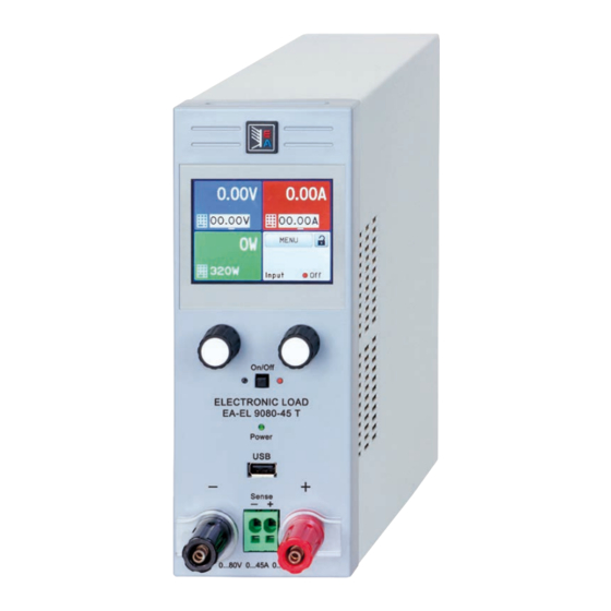
Page 82: Views
EL 9000 T Series 1.8.4 Views Figure 1 - Front side Figure 2 - Back side (delivery version with USB only) A - Touch screen F - Remote control interfaces (digital, analog) B - Adjustment knobs G - Fan exhausts... - Page 83 EL 9000 T Series Figure 3 - Side view from right Figure 4 - Top view EA Elektro-Automatik GmbH Fon: +49 2162 / 3785-0 www.elektroautomatik.de Page 13 Helmholtzstr. 31-37 • 41747 Viersen Fax: +49 2162 / 16230 ea1974@elektroautomatik.de Germany...
-
Page 84: Control Elements
EL 9000 T Series 1.8.5 Control elements Overview of the elements of the operating panel For a detailed description see section „1.9.5. The control panel (HMI)“ and „1.9.5.2. Rotary knobs“. Touchscreen display Used for selection of set values, menus, status and display of actual values. -
Page 85: Construction And Function
1.9.1 General description The conventional, electronic DC loads of the EL 9000 T series with their small desktop enclosure in tower design are especially suitable for research laboratories, test applications or educational. Apart from basic functions of electronic loads, set point curves can be generated from the integrated function generator (sine, rectangular, triangular and other curve types). -
Page 86: The Control Panel (Hmi)
EL 9000 T Series 1.9.5 The control panel (HMI) The HMI (Human Machine Interface) consists of a display with touchscreen, two rotary knobs, a button and an USB port. 1.9.5.1 Touchscreen display The graphic touchscreen display is divided into a number of areas. The complete display is touch sensitive and can be operated by finger or stylus to control the equipment. - Page 87 EL 9000 T Series • Status indicators (lower right) This area displays various status texts and symbols: Display Description Locked The HMI is locked Unlocked The HMI is unlocked Remote: The device is under remote control from..Analog ..the (optional) rear analog interface ..the rear USB port...
-
Page 88: Usb Port (Back Side)
EL 9000 T Series 1.9.5.5 USB-Port (Front side) The frontal USB port, located below the LED “Power”, is intended for the connection of standard USB sticks. This can be used for uploading or downloading of sequences for the arbitrary function generator or data recording dur- ing all operation modes. -
Page 89: Ethernet Port
EL 9000 T Series 1.9.8 Ethernet port The Ethernet port is optional. Also see section 1.9.4. The port on the back side of the device is provided for com- munication with the device in terms of remote control or moni- toring. -
Page 90: Installation & Commissioning
2.3.2 Preparation Mains connection with an EL 9000 T series device is done via the included 1.5 meters long 3 pole mains cord. Dimensioning of the DC wiring to the source has to reflect the following: • The cable cross section should always be specified for at least the maximum current of the device. -
Page 91: Connection To Dc Sources
EL 9000 T Series 2.3.4 Connection to DC sources • When using the 45 A model, attention has to be paid to where the load is connected to the DC input terminals. The front-side 4mm connection point is only rated for max. 32 A! •... -
Page 92: Connecting The Analog Interface
EL 9000 T Series Figure 6 - Example for remote sensing wiring The connector Sense is a clamp terminal. It means for the remote sensing cables: • Insert cables: crimp sleeves onto the cable ends and simply push them into the bigger square hole • Remove cables: use a small flat screwdriver and push into the smaller square hole below the bigger one to loosen... -
Page 93: Initial Commission
EL 9000 T Series 2.3.9 Initial commission For the first start-up after purchasing and installing the device, the following procedures have to be executed: • Confirm that the connection cables to be used are of a satisfactory cross section! • Check if the factory settings of set values, safety and monitoring functions and communication are suitable for your intended application of the device and adjust them if required, as described in the manual! • In case of remote control via PC, read the additional documentation for interfaces and software! -
Page 94: Operation And Application
EL 9000 T Series Operation and application Personal safety • In order to guarantee safety when using the device, it is essential that only persons operate the device who are fully acquainted and trained in the required safety measures to be taken when working with dangerous electrical voltages • For models which accept dangerous voltages, a protection against unwanted physical contact... -
Page 95: Current Regulation / Constant Current / Current Limitation
EL 9000 T Series 3.2.2 Current regulation / constant current / current limitation Current regulation is also known as current limitation or constant current mode (CC) and is fundamental to the normal operation of an electronic load. The DC input current is held at a predetermined level by varying the internal resistance according to Ohm’s law R = U / I such that, based on the input voltage, a constant current flows. -
Page 96: Dynamic Characteristics And Stability Criteria
EL 9000 T Series See the diagrams below for clarification. Principle derating progression 600W Peak power The maximum power is absorbed by the load device for a time x, before derating starts. After the start of derating, the available 550W... -
Page 97: Alarm Conditions
EL 9000 T Series Alarm conditions This section only gives an overview about device alarms. What to do in case your device indi- cates an alarm condition is described in section „3.6. Alarms and monitoring“. As a basic principle, all alarm conditions are signalled optically (text + message in the display) and as a readable status and alarm counter via the digital interface. -
Page 98: Manual Operation
EL 9000 T Series Manual operation 3.4.1 Powering the device The device should, as far as possible, always be switched on using the toggle switch on the rear of the device. After switching on, the display will first show the company logo, followed by a language selection which will close automatically after 3 seconds and later manufacturer’s name and address, device type, firmware version(s), serial... - Page 99 EL 9000 T Series EA Elektro-Automatik GmbH Fon: +49 2162 / 3785-0 www.elektroautomatik.de Page 29 Helmholtzstr. 31-37 • 41747 Viersen Fax: +49 2162 / 16230 ea1974@elektroautomatik.de Germany...
- Page 100 EL 9000 T Series EA Elektro-Automatik GmbH Fon: +49 2162 / 3785-0 www.elektroautomatik.de Page 30 Helmholtzstr. 31-37 • 41747 Viersen Fax: +49 2162 / 16230 ea1974@elektroautomatik.de Germany...
- Page 101 EL 9000 T Series EA Elektro-Automatik GmbH Fon: +49 2162 / 3785-0 www.elektroautomatik.de Page 31 Helmholtzstr. 31-37 • 41747 Viersen Fax: +49 2162 / 16230 ea1974@elektroautomatik.de Germany...
- Page 102 EL 9000 T Series 3.4.3.1 Menu “Settings” This is main menu for all settings related to the general operation of the device and of the interface(s). Sub menu P. Description Input Settings Allows for adjustment of set values related to the DC input, alternatively to the...
- Page 103 EL 9000 T Series Setting P. Description Analog interface Rem-SB This parameter is only display if the optional analog interface is installed. Selects how the input pin “Rem-SB” of the analog interface shall be working regarding levels and logic: • Normal = Levels and function as described in the table in 3.5.4.4 • Inverted = Levels and function will be inverted...
- Page 104 EL 9000 T Series Element Description Subnet mask Only available with setting “Manual”. Default value: 255.255.255.0 Manual setting of the subnet mask in standard IP format (setting will be stored) Gateway Only available with setting “Manual”. Default value: 192.168.0.1 Manual setting of the gateway address in standard IP format (setting will be stored) Submenu “IP Settings 2”...
- Page 105 EL 9000 T Series 3.4.3.8 Menu “HMI Setup” These settings refer exclusively to the control panel (HMI). Element Description Language Selection of the display language between German, English, Russian or Chinese. This selection screen is also shown for 3 seconds during the startup phase of the device.
-
Page 106: Adjustment Limits
EL 9000 T Series 3.4.4 Adjustment limits Adjustment limits are only effective on the related set values, no matter if using manual adjust- ment or remote control! The limits settings could be locked by a PIN (see MENU, “Limits lock”) Defaults are, that all set values (U, I, P, R) are adjustable from 0 to 102% of the corresponding rated value. -
Page 107: Manual Adjustment Of Set Values
EL 9000 T Series 3.4.6 Manual adjustment of set values The set values for voltage, current, power and resistance are the fundamental operating possibilities of an elec- tronic load and hence the two rotary knobs on the front of the device are always assigned to two of the four values in manual operation. -
Page 108: Switching The Dc Input On Or Off
► How to remotely switch the DC input on or off via the digital interface See the external documentation “Programming Guide ModBus & SCPI” if you are using custom software, or refer to the external documentation of LabView VIs or other documentation provided by EA Elektro-Automatik. EA Elektro-Automatik GmbH Fon: +49 2162 / 3785-0 www.elektroautomatik.de... -
Page 109: Recording To Usb Stick (Logging)
EL 9000 T Series 3.4.9 Recording to USB stick (logging) Device data can be recorded to USB stick (2.0, 3.0, not all vendors supported) anytime. For specifications of the USB stick and the generated log files refer to section „1.9.5.5. USB-Port (Front side)“. -
Page 110: Remote Control
Programming details for the interfaces, the communication protocols etc. are to be found in the documentation “Programming Guide ModBus & SCPI“ which is supplied on the included USB stick or which is available as down- load from the EA Elektro-Automatik website. EA Elektro-Automatik GmbH Fon: +49 2162 / 3785-0 www.elektroautomatik.de... -
Page 111: Remote Control Via The Analog Interface (Ai)
EL 9000 T Series 3.5.4 Remote control via the analog interface (AI) 3.5.4.1 General The optionally available, galvanically isolated, 15-pole analog interface (short: AI, also see section 1.9.9) is located on the back side of the device after installation and offers the following possibilities: • Remote control of current, voltage, power and resistance... - Page 112 EL 9000 T Series 3.5.4.3 Acknowledging device alarms Device alarms (see 3.6.2) are always indicated in the front display and some of them are also reported as signal on the analog interface socket (see table below). In case of a device alarm occurring during remote control via analog interface, the DC input will be switched off the same way as in manual control.
- Page 113 EL 9000 T Series 3.5.4.5 Overview of the Sub-D Socket 3.5.4.6 Simplified diagram of the pins Digital Input (DI) Analog Input (AI) It requires to use a switch with low resist- High resistance input (impedance V~0.5 ance (relay, switch, circuit breaker etc.) in >40 k..100 kΩ) for an OA circuit.
- Page 114 EL 9000 T Series • Remote control is not active In this mode of operation pin “REM-SB” can serve as lock, preventing the DC input from being switched on by any means. This results in following possible situations: Parameter Behaviour input „REM-SB“...
-
Page 115: Alarms And Monitoring
EL 9000 T Series Alarms and monitoring 3.6.1 Definition of terms There is a clear distinction between equipment alarms (see „3.3. Alarm conditions“) such as overvoltage or over- heating, and user defined events such as e.g OVD overvoltage monitoring.Whilst device alarms primarily serve to protect the source by switching off the DC input, user defined events can also switch off the DC input (Action = ALARM), but can also simply make the user aware by a pop-up in the display. - Page 116 EL 9000 T Series Some device alarms are configurable: Alarm Meaning Description Range Indication OverVoltage Triggers an alarm if the DC input voltage reaches the Display, analog & 0 V...1.03*U Protection defined threshold. The DC input will be switched off..
-
Page 117: Control Panel (Hmi) Lock
EL 9000 T Series ► How to configure user defined events While the DC input is switched off, tap the touch area on the main screen. In the menu tap on “Settings”, then on “Page 2” and there on “Event Settings”. -
Page 118: Limits Lock
EL 9000 T Series Limits lock In order to avoid the alteration of the adjustment limits (also see „3.4.4. Adjustment limits“) by an unprivileged user, the screen with the adjustment limit settings (“Limits”) can be locked by a PIN code. The menu pages “Limit Settings”... - Page 119 EL 9000 T Series ► How to load a user profile to work with While the DC input is switched off, tap the touch area on the main screen In the menu page, tap on “Page 2” and then on “Profiles”.
-
Page 120: The Function Generator
EL 9000 T Series 3.10 The function generator 3.10.1 Introduction The built-in function generator (short: FG) is able to create various signal forms and apply these to the set value of voltage or current. All standard functions are based on the also available arbitrary generator. During manual control, the standard functions such as sine wave can be selected and uses separately. -
Page 121: Manual Operation
EL 9000 T Series 3.10.4 Manual operation 3.10.4.1 Function selection and control Via the touchscreen one of the functions described in 3.10.1 can be called up, configured and controlled. Selection and configuration are only possible when the input is switched off. -
Page 122: Sine Wave Function
EL 9000 T Series ► How to start and stop a function The function can be started either by tapping or pushing the “On/Off” button, if the DC input is currently switched off. The function then starts immediately. In case START is used while the DC input is still switched off, the DC input will be switched on automatically. -
Page 123: Rectangular Function
EL 9000 T Series Schematic diagram: Application and result: A triangular wave signal for input current or input voltage is generated. The positive and negative slope times are variable and can be set independently. The offset shifts the signal on the Y-axis. -
Page 124: Trapezoidal Function
EL 9000 T Series 3.10.8 Trapezoidal function The following parameters can be configured for a trapezoidal curve function: Value Range Description Ampl. 0...(Nominal value - Offset) of U, I Amplitude of the signal to be generated Offset Ampl...(Nominal value - Ampl.) of U, I Offset of the foot of the trapezoidal wave against 0 0.01 ms...36000 s... -
Page 125: 3.10.10 Arbitrary Function
EL 9000 T Series 3.10.10 Arbitrary function The arbitrary (freely definable) function offers the user further scope. There are 100 sequence points available for use on current I or voltage U, all of which have the same parameters but which can be differently configured so that a complex function process can be built up. - Page 126 EL 9000 T Series Schematic diagram: Applications and results: Example 2 Focussing 1 cycle of 1 sequence from 100: The DC values at start and end are the same but the AC (amplitude) not. The end value is higher than the start so that the amplitude increases with each new half sine wave continuously through the sequence.
- Page 127 EL 9000 T Series By linking together a number of differently configured sequences, complex progressions can be created. Smart configuration of the arbitrary generator can be used to match triangular, sine, rectangular or trapezoidal wave func- tions and thus, e.g. a sequence of rectangular waves with differing amplitudes or duty cycles could be produced.
- Page 128 EL 9000 T Series 3.10.10.1 Loading and saving the arbitrary function The 100 sequence points of the arbitrary function, which can be manually configured with the control panel of the device and which are applicable either to voltage (U) or current (I), can be saved to or loaded from a common USB stick via the front side USB port.
-
Page 129: 3.10.11 Battery Test Function
EL 9000 T Series ► How to save a sequence point table to an USB stick: Do not plug the USB stick yet or remove it. Access the function selection menu of the function generator via MENU -> Function Generator -> Arbitrary... - Page 130 EL 9000 T Series 3.10.11.2 Parameters for dynamic mode The following parameters can be configured for the dynamic battery test function. Value Range Description 0...Nominal value of I Upper resp. lower current setting for pulsed operation (the higher value of both is automatically used as upper level) 0...Nominal value of I...
-
Page 131: 3.10.12 Mpp Tracking Function
EL 9000 T Series 3.10.11.5 Data recording (USB logging) At the end of the configuration of both, static and dynamic mode, there is the option to enable the USB logging feature. With an USB stick plugged and formatted as required (see ), the device can record data during the test run directly to the stick and in the defined interval. - Page 132 EL 9000 T Series 3.10.12.1 Mode MPP1 This mode is also called “find MPP”. It is the simplest option to have the electronic load find the MPP of a connected solar panel. It requires to set only three parameters. Value U is necessary, because it helps to find the MPP quicker as if the load would start at 0 V or maximum voltage.
-
Page 133: 3.10.13 Remote Control Of The Function Generator
EL 9000 T Series Value Range Description Δt 5 ms...65535 ms Interval for measuring U and I during the process of finding the MPP ΔP 0 W...P Tracking/regulation tolerance below the MPP 3.10.12.4 Mode MPP4 This mode is different, because it does not track automatically. It rather offers the choice to define a user curve by setting up to 100 points of voltage values, then track this curve, measure current and power and return the results in up to 100 sets of acquired data. -
Page 134: Service And Maintenance
Contact the supplier in case of suspicion and elicit the steps to be taken. It will then usually be necessary to return the device to Elektro-Automatik (with or without warranty). If a return for checking or repair is to be carried out, ensure that: • the supplier has been contacted and it is clarified how and where the equipment should be sent. -
Page 135: Calibration
EL 9000 T Series Calibration 4.3.1 Preface The devices of series EL 9000 T feature a function to re-adjust the most important input related values when doing a calibration and in case these values have moved out of tolerance. The re-adjustment is limited to compensate small differences of up to 1% or 2% of the max. - Page 136 EL 9000 T Series 4.3.3.1 Set values ► How to calibrate the voltage Adjust the connected voltage source to approx. 102% of the maximum voltage specified for the EL device. For the example with an 80 V EL this would be 81.6 V for the source. Set the current limitation of the voltage source to >5% of the nominal current specified for EL device, for this...
-
Page 137: Contact And Support
Contact and support Repairs Repairs, if not otherwise arranged between supplier and customer, will be carried out by EA Elektro-Automatik. For this the equipment must generally be returned to the manufacturer. No RMA number is needed. It is sufficient to package the equipment adequately and send it, together with a detailed description of the fault and, if still under guarantee, a copy of the invoice, to the following address. - Page 140 EA-Elektro-Automatik GmbH & Co. KG Development - Production - Sales Helmholtzstraße 31-37 41747 Viersen Germany Fon: +49 2162 / 37 85-0 Fax: +49 2162 / 16 230 Mail: ea1974@elektroautomatik.de Web: www.elektroautomatik.de Distributed by: Sie haben Fragen oder wünschen eine Beratung? Angebotsanfrage unter 07121 / 51 50 50 oder über info@datatec.de...
Need help?
Do you have a question about the EL 9000 T Series and is the answer not in the manual?
Questions and answers