Table of Contents
Advertisement
Quick Links
Advertisement
Table of Contents

Subscribe to Our Youtube Channel
Related Manuals for meitav-tec PYROBOX3/19


Summary of Contents for meitav-tec PYROBOX3/19
- Page 1 PYROBOX3/19 PYROBOX3C/19 PYROBOX5/19 Installation and Operating manual Rev. 5.3.7...
-
Page 2: Table Of Contents
Index Introduction…………………………………………………………………...……. 4 PYROBOX Installation notes ……...…………...……………………………….. 5 Wiring the PYROBOX3/19………………………………………………………. 6 Wiring the PYROBOX3C/19…….………………………………………………. 7 Wiring the PYROBOX5/19………………………………………………………. 8 Connecting snow sensors and PYROBOX/19 slaves……………….……..9 Installation and Wiring Connections – PYROSENSE…………………………10 Installation and Wiring Connections – PYROSENSE-GUTTER……………. 11 Installation and Wiring Connections –... -
Page 3: Index
Index DIP Switch settings……………………………………………………………….. 25 DIP switch S2 - Short measuring times (test only) …………………………... 25 DIP switches S3 and S4 – heaters sequencing logic………………………... 25 Enable/Disable zones ………………………………………………………...…. 26 Select critical zones……….…………………………………………………...…. 27 BMS communication protocol – BACnet/Modbus (DIP switch S6) …...…. 28 Temperature reading errors……………………………………………………... -
Page 4: Introduction
Introduction The PYROBOX3/3C/5/19/19 power boxes together with the PYROCON12/19 controller and interface panel, offer smart and easy control over the PYRO Snow & Ice Melting system. It can operate up to 4 snow melting zones and one auxiliary zone, with selectable sequencing method. Typical applications include driveways, sidewalks, loading docks, stairs, pavements and gutters. - Page 5 PYROBOX Series Installation PLEASE READ THIS MANUAL AND THE SAFETY WARNINGS CAREFULLY BEFORE INSTALLING AND USING THE CONTROLLER AND SAVE IT FOR FUTURE USE Installation notes Familiarize yourself with the markings, warnings, components and terminology. The PYROBOX power boxes and its accessories must be installed by a qualified electrician in accordance with local regulations and the requirements of the NEC (NFPA 72 ) and the CEC part 1.
-
Page 6: Wiring The Pyrobox3/19
Wiring the PYROBOX3/19 Caution: Incorrect voltage may cause fire or seriously damage the unit. Make sure the wire gauge (AWG) is suitable for the circuit Amperage draw, as specified T3 T2 B2 A2 in the NEC/CEC table 1. Reset Test... -
Page 7: Wiring The Pyrobox3C/19
Wiring the PYROBOX3C/19 Caution: Incorrect voltage may cause fire or seriously damage the unit. Make sure the wire gauge (AWG) is suitable for the circuit Amperage draw, as specified T3 T2 B2 A2 in the NEC/CEC table 1. Reset Test PYROCON19 GFEP 1 2 Z5 22... -
Page 8: Wiring The Pyrobox5/19
Wiring the PYROBOX5/19 Caution: Incorrect voltage may cause fire or seriously damage the unit. 3-P Contactors C1,C2,C3,C4 Contactor C5 Make sure the wire gauge (AWG) is suitable 600VAC, 50A Max. per pole 277VAC, 30A Max. for the circuit Amperage draw, as specified T3 T2 B2 A2 in the NEC/CEC table 1. - Page 9 Connecting communicating sensors and PYROBOX/19 slaves Power Device/Sensor Number of Power/Comm. consumption type sensors/devices cable length Address (24VAC) PYROSENSE Up to 4 32.8ft / 10m Aerial sensor Ground sensors Up to 2 15.6VA 32.8ft / 10m Gutter sensor Up to 2 32.8ft / 10m PYROBOX/19 Up to 3...
-
Page 10: Installation And Wiring Connections - Pyrosense
Installation and Wiring Connections – PYROSENSE Wall mount installation Roof installation Roof side installation The PYROSENSE aerial sensors are supplied with: 1. A plastic cap, to protect the sensor from dust and debris for when the sensor is not in use (off season). Important! The protective cap must be removed before use of the sensor. - Page 11 Installation and Wiring Connections – PYROSENSE Power cable (R,C) Power cable (R,C) 18AWG - Up to 500ft / 150m 18AWG - Up to 500ft / 150m 12AWG - Up to 1000ft / 300m 12AWG - Up to 1000ft / 300m Communication cable (A,B) Communication cable (A,B) Jacketed shielded twisted...
-
Page 12: Installation And Wiring Connections - Pyrosense-Gutter
Installation and Wiring Connections – PYROSENSE-GUTTER Power cable (R,C) Communication cable (A,B) 18AWG - Up to 500ft / 150m Jacketed shielded twisted 12AWG - Up to 1000ft / 300m pair 120 Ohm, 18AWG - Up to 500ft / 150m Gutter sensor installation Installation and Wiring Connections –... -
Page 13: Operating Instructions
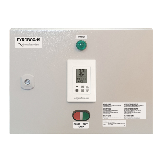
Operating instructions Green POWER lamp GFEP Test/Reset button The green power lamp will light when TEST GFEP (GREEN button) power is supplied to the unit (120 VAC) GROUND FAULT RESET lamp will lit when the internal GFEP is tripped RESET GFEP (RED button) - Press for 5 seconds Turning the system ON and OFF Press and hold the [ON] button for 0.5 seconds to turn... -
Page 14: Technician Settings
Technician settings Use the technician settings to view and adjust the following parameters: Temperature set point Lower ambient temperature limit to stop heaters Energy saving, upper slab temperature limit to stop heaters Time delay before stopping the heaters ON time for manual mode Heaters cycle time / Splitting time Sensors and heaters control logic Snow sensor sensitivity... -
Page 15: P01 - Temperature Set Point
Technician settings P01 - Temperature set point Move DIP switch S1 located on the side of thermostat to ON position to enter technician settings mode. “P01” and the temperature set point will appear on display. Use the [+] and [-] buttons to adjust the temperature set point. Range: 14…59°F / -10…+15°C, default 37°F / +3°C Temperature set point... -
Page 16: P03 - Upper Limit Temperature For Heating
Technician settings (Cont’) P03 – Upper limit temperature for heating Press the [SELECT] and [+] buttons simultaneously. “P03” and the slab upper limit temperature will appear on display. Use the [+] and [-] buttons to adjust the upper limit temperature. Range: +41…+122°F / +5…+50°C Default: 86°F / +30°C *For numbers above 100, “100”... -
Page 17: P05 - Manual Mode On Time
Technician settings (Cont’) P05 - Manual mode ON time Press the [SELECT] and [+] buttons simultaneously. “P05”, “On” and the “Manual ON” mode time period will appear on display. The hours will blink. The delay time parameter defines a time frame in which the heaters remain ON after receiving an “Manual ON”... -
Page 18: Rd Party Sensor
Technician settings (Cont’) P07 - Heaters outputs logic controlled by PYRO sensors or by 3 party sensor Press the [SELECT] and [+] buttons simultaneously. “P07” and the figures “0”, “1”, “2” or “3” will appear on display. Use the [+] and [-] buttons to define the heaters logic (model dependent) as follows: Heaters controlled by Heaters controlled by Heaters controlled by... -
Page 19: P08 - Snow Sensor Sensitivity
Technician settings (Cont’) P08 - Snow sensor sensitivity Press the [SELECT] and [+] buttons simultaneously. “P08” and the snow sensor sensitivity value will appear on display. Use the [+] and [-] buttons to adjust the sensitivity. Range: 20...80 % (20% - Less sensitive, 80% - more sensitive), Default: 50 % Snow sensor sensitivity P88 - Snow detection threshold... - Page 20 Technician settings (Cont’) P09 – Enable/Disable PYROSENSE sensors connected to system Important! When new sensors are connected to the system, please refer to technician parameter P13 - scan the system for new sensors. After the scanning process explained in P13 completes, the sensors found can be enabled or disabled.
-
Page 21: P10 - Test Conditions Mode
Technician settings (Cont’) P10 - Test conditions mode / Technician commissioning mode Turn ON test conditions to check the functionality of the system regardless of sensors parameters (i.e. during the summer). In test conditions, the Ambient temperature is always -5°C/23°F. Note: In order to trigger the system and activate the heaters, use some water to wet the circuit on top of the snow sensor. -
Page 22: P12 - Controller's Mac Address
Technician settings (Cont’) P12 – Controller’s MAC Address Press the [SELECT] and [+] buttons simultaneously. “P12” will appear on display. Use the [+] and [-] buttons to set the controller’s MAC address: - For controller set by P11 as Master – Address range for BMS 1...63, default 9 MAC Address MAC Address... - Page 23 Technician settings (Cont’) P13 – Scan the system for new sensors Important! Disconnect power to the main board before installing new sensors. The system can recognize up to 3 different sensors in one scanning loop: - One PYROSENSE aerial, One PYROSENSE-GROUND and One PYROSENSE-GUTTER If more than one sensor of the same type is used, connect the first sensor and run the scanning procedure.
-
Page 24: P14 - Reset Pyro Sensors Mac Address
Technician settings (Cont’) P14 – Reset PYRO Sensors MAC Address Press the [SELECT] and [+] buttons simultaneously. “P14” will appear on display. Use the [+] and [-] buttons to select sensor by its MAC address. Press the [ON] button to reset the sensor’s MAC address. If required, run the sensors scanning procedure again –... - Page 25 Technician settings (Cont’) DIP switch S2 - Short measuring times (test only) Use DIP switch S2 to short the - “ON” - Short measuring times – for test/commissioning only (measuring times will be divided to 60). - “OFF” - Normal operation. Short measuring times: A real 1 hour will take 1 minute and a real 1 minute will take 1 second.
- Page 26 Technician settings (Cont’) Enable/Disable zones Follow the steps below to enable or disable each of the 5 zones. By default, all zones are enabled. 1. Turn the thermostat OFF. 2. Press and hold both the [+] and the [-] buttons simultaneously for 10 seconds. 3.
- Page 27 Technician settings (Cont’) Select Critical zones Follow the steps below to set each of the active zones as Critical or Non-critical zone. By default, all zones are critical. 1. Turn the thermostat ON. 2. Press and hold both the [+] and the [-] buttons simultaneously for 10 seconds. 3.
- Page 28 BMS Communication Protocol – BACnet/Modbus Use DIP switch S6 located on the side of thermostat to select BMS (A1,B1) network protocol: S6 ON – BACnet, S6 OFF – MODBUS Modbus BACnet Important! When using Master-Slave logic, the BMS communication protocol should be set only on the Master unit.
- Page 29 = “Pyrocon 19” Supported Commands: User Application Name = “Pyrocon 19” 0x03 = Read Holding Registers (for all). VendorName = "Meitav-Tec". 0x06 = Preset Single Register (For R/W registers only), ProductCode = "19418301" Command 0x2B is used to identify controller MajorMinorRevision = "0.1.2257”...
- Page 30 Object list – BACnet (DIP switch S6 = ON) BACnet MSTS Baud rate: 9600, 19200, 38400, 76800 no parity, 8 data bits, 1stop bit N° Object Value Object name Default Perm. TS AnalogValue_#0 -10...15°C (14...59°F) SetPoint 3°C (37°F) AnalogValue_#1 -40...0°C (-40...32°F) LowLimitHeat -35°C (-31°F) R/W AnalogValue_#2...
- Page 31 Appendix 1 Calibrating and testing the internal GFEP The GFEP (Ground Fault Equipment Protection) is designed to provide protection for electrical equipment. The “ON” Time Delay and Current Trip should be configured to match application requirements. SUPPLY “ON” Time delay TIME DELAY Remote C.T.
- Page 32 Tel: (856) 2882882 Tel: +972-3-9626462 Fax: +972-3-9626620 support@meitavtec.com www.meitavtec.com...
Need help?
Do you have a question about the PYROBOX3/19 and is the answer not in the manual?
Questions and answers