
Subscribe to Our Youtube Channel
Related Manuals for MKS Newport 1801


Summary of Contents for MKS Newport 1801
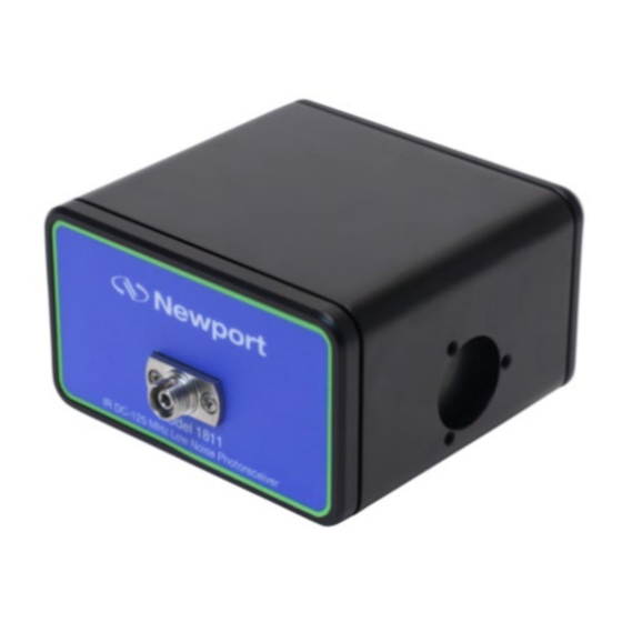
- Page 1 PART 90099905. REV B- 6/28/23 User‘s Manual 125 MHz PHOTORECEIVERS MODELS 1801 AND 1811 1791 DEERE AVENUE FAX: (949) 253.1680 IRVINE, CA 92606 E-MAIL: TECH@NEWPORT.COM WWW.NEWPORT.COM (877) 835.9620 OR (949) 863.3144...
- Page 2 All rights reserved. No part of this work may be reproduced or transmitted in any form or by any means, electronic or mechanical, including photocopying and recording, or by any information storage or retrieval system, except as may be expressly permitted in writing by MKS Instruments, Inc. mksinst™ is a trademark of MKS Instruments, Inc.
-
Page 3: Table Of Contents
USER‘S MANUAL PART 90099905. REV B-6/28/23 Table of Contents List of Figures and Tables ......................... 4 1 Warranty ............................... 5 Limitation of Warranty ......................... 5 2 Safety Information ..........................6 Safety Procedures and Precautions ................... 6 Symbols Used in This Instruction Manual ................... 6 3 Operation .............................. -
Page 4: List Of Figures And Tables
USER‘S MANUAL PART 90099905. REV B-6/28/23 List of Figures and Tables Figure 1: Functional block diagram of Models 1801 & 1811 (DC versions)..........10 Figure 2: Functional block diagram of Models 1801 & 1811 (AC versions)..........10 Figure 3: Responsivity of the photodiode used in the Model 1801 (DC version)........11 Figure 4: Responsivity of the photodiode used in the Model 1811 (DC version). -
Page 5: Warranty
USER‘S MANUAL PART 90099905. REV B-6/28/23 1 Warranty Newport Corporation warrants that this product will be free from defects in material and workmanship and will comply with Newport’s published specifications at the time of sale for a period of one year from date of shipment. -
Page 6: Safety Information
DO NOT SUBSTITUTE PARTS OR MODIFY INSTRUMENT Do not install substitute parts or perform any unauthorized modification to the instrument. Return the instrument to an MKS Calibration and Service Center for service and repair to ensure that all safety features are maintained. -
Page 7: Operation
USER‘S MANUAL PART 90099905. REV B-6/28/23 3 Operation 3.1 Introduction The Newport Models 1801 and 1811 125-MHz, low noise photoreceivers address the needs of the photodetector community in the area of low-noise, high-gain, RF photoreception. These photoreceivers are available either DC or AC coupled. Their typical bandwidth is 125 MHz with a current gain of 40 V/mA. -
Page 8: Handling Precautions
USER‘S MANUAL PART 90099905. REV B-6/28/23 3.2 Handling Precautions Whenever handling the photo receiver, make sure to follow these precautions: Prior to handling the unit or making connections, be sure to ground yourself adequately-even • small electrostatic discharges could permanently damage the device. A ground strap provides the most effective grounding and minimizes the likelihood of electrostatic damage. -
Page 9: Theory
USER‘S MANUAL PART 90099905. REV B-6/28/23 2. If your instrument has a female connector, connect with the appropriate cable. 3. On AC-coupled units, monitor the DC bias on the output labeled “DC” with the provided SMB- to-BNC cable. 3.4 Theory The Model 1801 photoreceiver contains a silicon/PIN photodiode. - Page 10 USER‘S MANUAL PART 90099905. REV B-6/28/23 Figure 1: Functional block diagram of Models 1801 & 1811 (DC versions). Figure 2: Functional block diagram of Models 1801 & 1811 (AC versions). PAGE 10 OF 17 | 125 MHZ PHOTORECEIVERS...
- Page 11 USER‘S MANUAL PART 90099905. REV B-6/28/23 Figure 3: Responsivity of the photodiode used in the Model 1801 (DC version). Figure 4: Responsivity of the photodiode used in the Model 1811 (DC version). PAGE 11 OF 17 | 125 MHZ PHOTORECEIVERS...
- Page 12 USER‘S MANUAL PART 90099905. REV B-6/28/23 Figure 5: Typical frequency response Figure 6: Typical input referred noise of the 18x1 products PAGE 12 OF 17 | 125 MHZ PHOTORECEIVERS...
- Page 13 USER‘S MANUAL PART 90099905. REV B-6/28/23 Figure 7: Typical output noise of the 18x1 products PAGE 13 OF 17 | 125 MHZ PHOTORECEIVERS...
-
Page 14: Characteristics
USER‘S MANUAL PART 90099905. REV B-6/28/23 4 Characteristics 4.1 Physical Specifications Figure 8. Mechanical drawings oft he Model 18X1 housing. PAGE 14 OF 17 | 125 MHZ PHOTORECEIVERS... -
Page 15: Photodetector Specifications
USER‘S MANUAL PART 90099905. REV B-6/28/23 4.2 Photodetector Specifications Table 1. 1801 and 1811 series specifications. Model 1801 1811 Wavelength Range 320–1000 nm 900–1700 nm Coupling DC or AC DC or AC 3-dB Bandwidth DC–125 MHz typical DC–125 MHz typical (DC versions) 3-dB Bandwidth 25 kHz–125 MHz... -
Page 16: Customer Service
USER‘S MANUAL PART 90099905. REV B-6/28/23 5 Customer Service 5.1 Technical Support Information and advice about the operation of any Newport product is available from our technical support engineers. For quickest response, ask for “Technical Support” and know the model number and serial number of your photoreceiver. - Page 17 USER‘S MANUAL PART 90099905. REV B-6/28/23 Index Input referred noise, 4, 12 Block diagram, 4, 9, 10 Noise, 4, 7, 9, 13 DC bias, 9 Power supply, 8 Electrostatic discharges, 5 Responsivity, 4, 11 Frequency response, 4, 9, 12 Specifications, 3, 14, 15 PAGE 17 OF 17 | 125 MHZ PHOTORECEIVERS...
Need help?
Do you have a question about the Newport 1801 and is the answer not in the manual?
Questions and answers