
Related Manuals for Heat Outdoors QHC24MR


Summary of Contents for Heat Outdoors QHC24MR
- Page 1 QHC24MR 24kW Heater Controller 3 channel (Receiver) Remote & Manual Operation Quick Start Guide & Instructions Three phase 415v / Three Zone / Remote & Manual / Soft start...
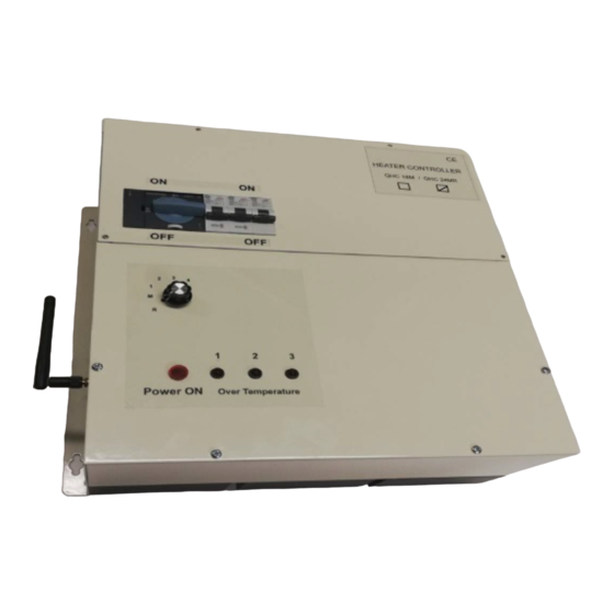
- Page 2 Quick Start for QHC24MR 24kW Heater Controller with Soft start Remote & Manual Operation. Service hatch Isolation switch 32A O/P MCBs 32A Type C Power control dial 5 settings Manual & Remote Power ON indicator Over Temp indicators Front panel...
- Page 3 Quick Start for QHC24MR See fig's 1,5 & 6 1) Start by removing the service hatch. Remove the 4 fixing screws, 2 at the top and 2 in the corners. There is a Din Rail revealed once the service hatch has been removed.
- Page 4 QHC24MR 24kW Heater Controller Din Rail & Connections Fig 5 Distribution Box P/No. QHDB18 or QHDB24 Fig 6 Terminals 1 – O/P1, Terminals 2 – O/P2, Terminals 3 – O/P3 Blue terminals N – N out, Green/Yellow terminals – Earth This item is sold separately Important ! Only a qualified electrician should install this device.
- Page 5 Controller Setup Manual Operation S1 & S2 To access S2, remove both the service hatch & front panel. S2 is found on the printed circuit boards QHPCB-A. There is a set on each board. See fig. 8 PIR & External Switches OFF - S2 Slide switch is set in the Off position (select 2) factory set.
- Page 6 QHVCR remote Master Controller (Transmitter) Fig 9 Supplied separately 1) There are three control dials Blue, Yellow & Red one for each zone. The QHCxxMR units are preset to operate in one of these zones. The QHCxxMR unit once preset will only operate in that designated zone.
- Page 7 Pairing (Programming) Devices QHVCR & QHCxxMR Fig 10 Pairing (programming) devices QHVCR (transmitter) and QHC18MR (receivers). 1) The Left Hand Side rotary switches (TEN) on both boards must be set the same. The LHS switch (TEN) is used to set the RF frequency the setting must match on both boards.
- Page 8 PIR Motion Detectors Connection & Operation PIR motion detectors are passive infrared sensors, an electronic device which is triggered by infrared light from the movement of objects in its field of view. We recommend the QHPIR is used with our QHC controllers. When using a PIR –...
- Page 9 External Switch Connection & Operation Push On/Push Off & Timer (10 minute) function External switches can be connected to the controller via terminals #18,19 & 20 a+b. This particular terminal is a Double deck terminal. The switch must be a normally open contact switch (NO) and contacts must be voltage free.
-
Page 10: Over Temperature Protection
Jumper Link (PIR) & Link Bar (External switch) Jumper Link and Link Bar & Mnt screws ID conns Red & Yellow with Jumper & Link Bar Jumper Link fitted to inputs #15-17 (PIR) & Link Bar fitted to inputs #18-20 (External switch) Fig 15 Connecting the Jumper Link to inputs terminals #15-17 allows for one PIR to control the unit. - Page 11 Fitting ID Connectors Red & Yellow Fig 16 Master 1 printed circuit board (PCB)is located in position 1, phase L1. This is the main board that controls the entire QHC18MR controller. The Slave 2 & 3 pcb's are located in positions 2 & 3, phases L2 &...
- Page 12 IP Rating: IP53 Dimensions : 350mm x 330mm x 150mm Note : Terminal connections are the same Weights : QHC24MR – 10 Kg for both the QH24M & QHC24MR controllers. Tel. 01279 466 500 Email: info@heat-outdoors.co.uk Unit 9 Stort Valley Industrial Estate, Bishop's Stortford, Hertfordshire, CM23 2TU, UK Website: www.heat-outdoors.co.uk...
Need help?
Do you have a question about the QHC24MR and is the answer not in the manual?
Questions and answers